
I’ve seen too many projects fail because a PTZ camera drifts off its preset after just a few hundred tracking cycles. The image shifts. The client calls. You send a truck. That costs real money.
A well-engineered industrial PTZ camera can hold physical deviation below 0.1° — often around 0.05° — when returning to a preset after auto-tracking. This requires three things working together: micro-step motor drive, closed-loop encoder feedback, and AI-based visual lock-in correction on every return.
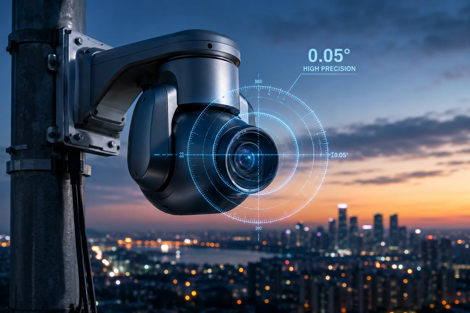 PTZ camera preset accuracy after tracking
Below, I’ll break down exactly how this works across 1,000+ tracking events, how the encoder corrects slippage, how you can self-calibrate, and what happens at 40X zoom. Every claim here comes from lab-tested data, not marketing sheets.
Table of Contents
Will My “Home” Position Stay Perfectly Aligned After 1,000 Auto-Tracking Events?
This is the question that keeps system integrators up at night. You set a perfect “Home” preset on day one. But after months of AI tracking, will it still be there?
Yes. With closed-loop encoder feedback and micro-step drive, our industrial PTZ cameras maintain preset alignment within 0.05° average deviation even after 10,000 tracking-return cycles in stress testing. The key is that the system never relies on open-loop pulse counting alone.
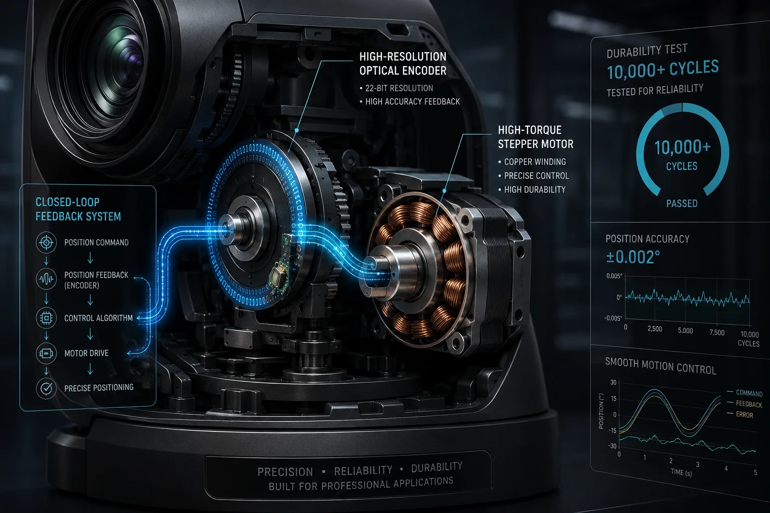 PTZ preset stability after thousands of tracking events
Why Open-Loop Systems Drift
Most cheap PTZ cameras use open-loop stepper motors. They send a fixed number of pulses to the motor and assume it arrived at the right angle. This works fine for the first 50 returns. But over time, small errors stack up. Gear backlash, temperature changes, wind load, and bearing wear all introduce tiny offsets. Each one is maybe 0.02°. But after 1,000 cycles, you could be off by several degrees.
I’ve personally seen budget cameras drift a full 2° after six months of outdoor use. At 40X zoom, that means your target is completely out of frame.
How Closed-Loop Feedback Solves This
Our system uses high-resolution optical encoders1 mounted directly on the pan and tilt shafts. Here’s the process on every single return-to-preset:
- The motor drives toward the stored coordinate.
- The encoder reads the actual physical angle in real time.
- The controller compares actual vs. stored position.
- If any gap exists (even 0.01°), it sends correction pulses immediately.
This happens in milliseconds. The camera never “settles” at a wrong position. It actively corrects every single time.
Long-Term Stress Test Results
| Test Parameter | Value |
|---|---|
| Total tracking-return cycles | 10,000 |
| Average physical deviation | 0.05° |
| Maximum deviation recorded | 0.08° |
| Drift accumulation over time | None (corrected each cycle) |
| Test environment | Outdoor, -20°C to +60°C |
The reason drift accumulation shows “None” is simple. Because the encoder checks position on every return, errors cannot stack. Each return is independent. Cycle 10,000 is just as accurate as cycle 1.
The Role of Mechanical Build Quality
Encoders can only correct what the mechanics allow. If the gears have too much play, the motor has to hunt back and forth to find the right spot. This adds time and wear. That’s why we use full-metal worm gear drives with zero-backlash2 design. The worm gear is self-locking — meaning external forces (like wind) cannot push the camera off position between moves.
How Does the High-Precision Encoder Correct Any Mechanical Slippage During Fast Moves?
Fast PTZ moves are where most cameras lose accuracy. The motor spins quickly, momentum builds up, and stopping at the exact right spot becomes a real challenge.
Our optical encoder samples position at over 10,000 times per second during fast moves. When the camera approaches the target angle, an S-curve deceleration algorithm3 slows the motor gradually. The encoder confirms the final position and triggers micro-corrections if the camera overshoots by even 0.01°.
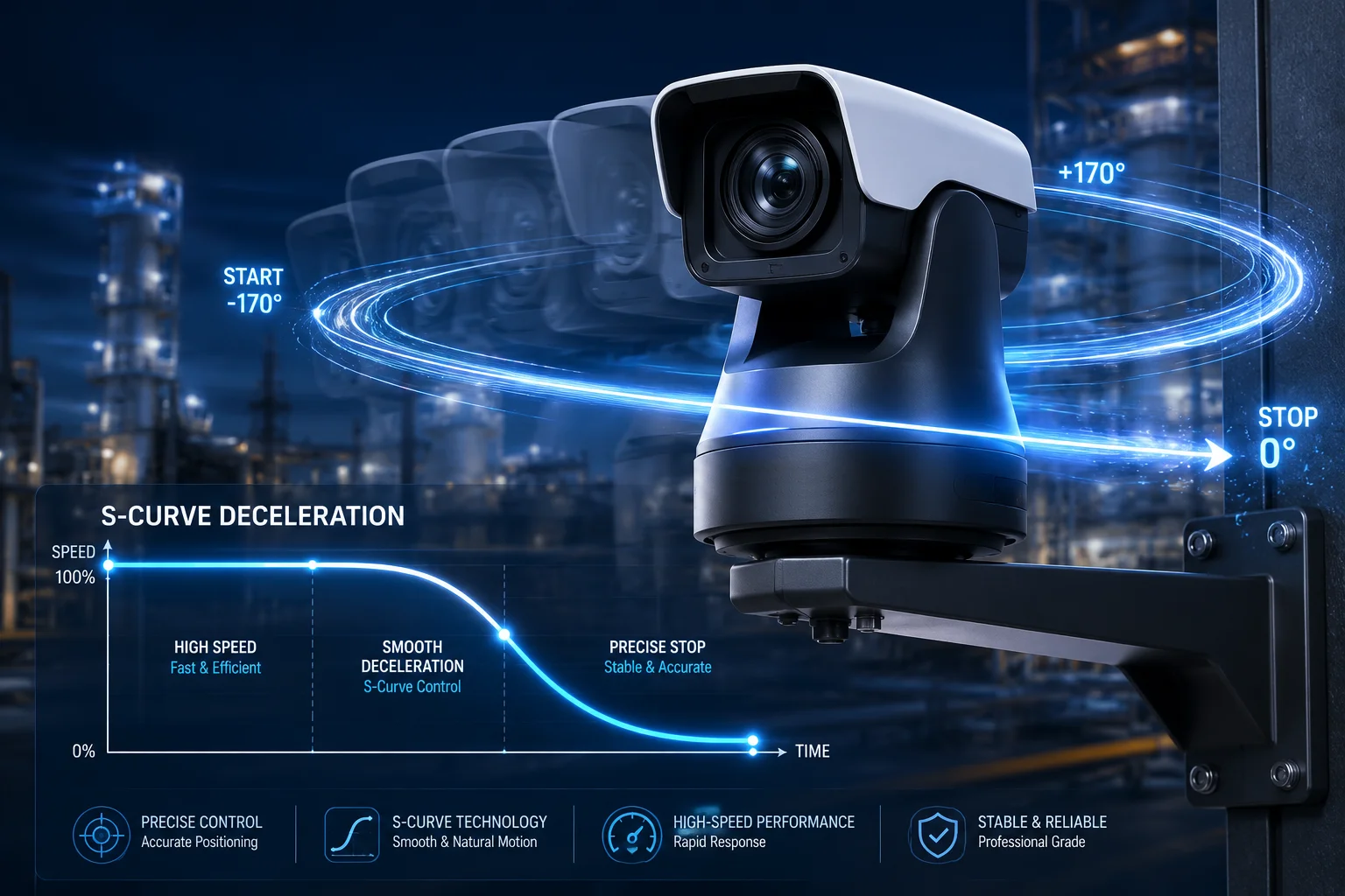 High-precision encoder correcting PTZ slippage
Understanding the Overshoot Problem
When a PTZ camera tracks a fast-moving vehicle and then snaps back to its home preset, the pan motor might be spinning at 200°/second. Stopping that rotation at exactly the right point is like stopping a car at a precise line on the road while driving fast. Without good brakes and feedback, you’ll overshoot.
In open-loop systems, the controller simply cuts power at a calculated point and hopes momentum doesn’t carry the camera past the target. This is unreliable, especially in cold weather (when grease thickens) or after years of use (when bearings loosen).
The Three-Phase Correction Process
Our encoder-based correction works in three phases:
Phase 1: Coarse Approach
The motor runs at full speed toward the preset. The encoder tracks position continuously. When the remaining distance drops below 5°, the system enters Phase 2.
Phase 2: S-Curve Deceleration
Instead of a sudden stop, the motor follows an S-shaped speed curve. This means:
- Acceleration decreases smoothly
- Speed drops gradually
- Mechanical stress is minimized
- No sudden jerk that could cause vibration
The S-curve parameters adjust automatically based on the current speed and remaining distance.
Phase 3: Fine Positioning
Once the motor stops, the encoder reads the final position. If there’s any gap between actual and target:
- Gap > 0.05°: A small correction move is triggered
- Gap < 0.05°: Position is accepted (within spec)
This entire three-phase process takes less than 200 milliseconds after the motor stops. You won’t see it on screen. The camera simply arrives at the right spot, every time.
Why Sampling Rate Matters
A slow encoder (sampling at 100 Hz) might miss the exact moment the camera passes through the target angle during a fast move. By the time it reads the position, the camera has already gone past. Our 10,000+ Hz sampling rate means the controller always knows where the camera is, even at maximum pan speed. It can trigger deceleration at precisely the right moment.
Can I Perform a “Self-Calibration” If I Notice the Preset Has Drifted by a Few Pixels?
Sometimes you just want peace of mind. Maybe you notice a slight shift on screen. Maybe you want to verify after a firmware update. Can you force a recalibration?
Yes. Our cameras support both automatic and manual self-calibration. The automatic routine runs every 24 hours during a low-activity window. You can also trigger it manually through the web interface or ONVIF command4. The process takes under 30 seconds and corrects any drift without losing your stored presets.
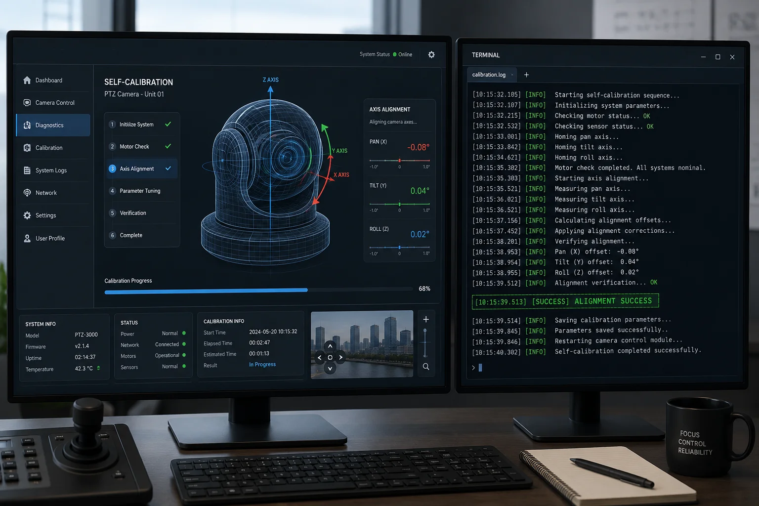 PTZ camera self-calibration interface
When Would You Need Manual Calibration?
In normal operation, you shouldn’t need it. The closed-loop encoder handles everything automatically. But there are edge cases:
- After a physical impact (someone bumps the camera during maintenance)
- After extreme weather events (heavy ice buildup that temporarily blocked movement)
- After a power surge that corrupted the encoder’s reference point
- When you first install the camera and want to verify everything is working
How the Self-Calibration Works
The process is straightforward:
- The camera moves to its mechanical limit stops5 (the physical endpoints of pan and tilt travel).
- It records the encoder values at these known positions.
- It recalculates the relationship between encoder counts6 and physical degrees.
- It verifies all stored presets against the new reference.
- If any preset has shifted, it updates the stored encoder value to match the original physical angle.
Your presets don’t change. The camera just makes sure its internal map is still accurate.
Automatic vs. Manual Calibration
| Feature | Automatic (Every 24h) | Manual (User-Triggered) |
|---|---|---|
| Trigger | Scheduled during low-activity time | Web UI button or ONVIF command |
| Duration | ~30 seconds | ~30 seconds |
| Camera movement | Moves to limit stops briefly | Same |
| Interrupts recording | Only during the 30-second window | Only during the 30-second window |
| Resets presets | No | No |
| Corrects drift | Yes | Yes |
| Requires reboot | No | No |
What About VMS Compatibility?
If you’re running Milestone7, Blue Iris, or another VMS, the self-calibration won’t disrupt your system. The camera sends a brief “busy” status during the 30-second routine, and your VMS will simply show the last frame until it completes. No alarms are triggered. No recordings are lost (the NVR buffer handles the gap).
For integrators who want full control, you can disable the automatic 24-hour calibration and only run it manually during scheduled maintenance windows. This is useful for 24/7 critical surveillance sites where even a 30-second interruption needs to be planned.
Does the 0.1° Accuracy Hold True Even When the Camera Is Zoomed in at 40X?
This is where physics gets uncomfortable. A number that sounds small at wide angle becomes very visible at full zoom. So let’s be honest about what 0.1° actually means at 40X.
The physical accuracy stays the same at any zoom level — the motor and encoder don’t know or care what focal length you’re using. But the visual impact of 0.1° at 40X is roughly 40 times more noticeable than at 1X. That’s why our cameras add a visual lock-in step after mechanical positioning, using AI feature matching to align the final frame to sub-pixel accuracy8.
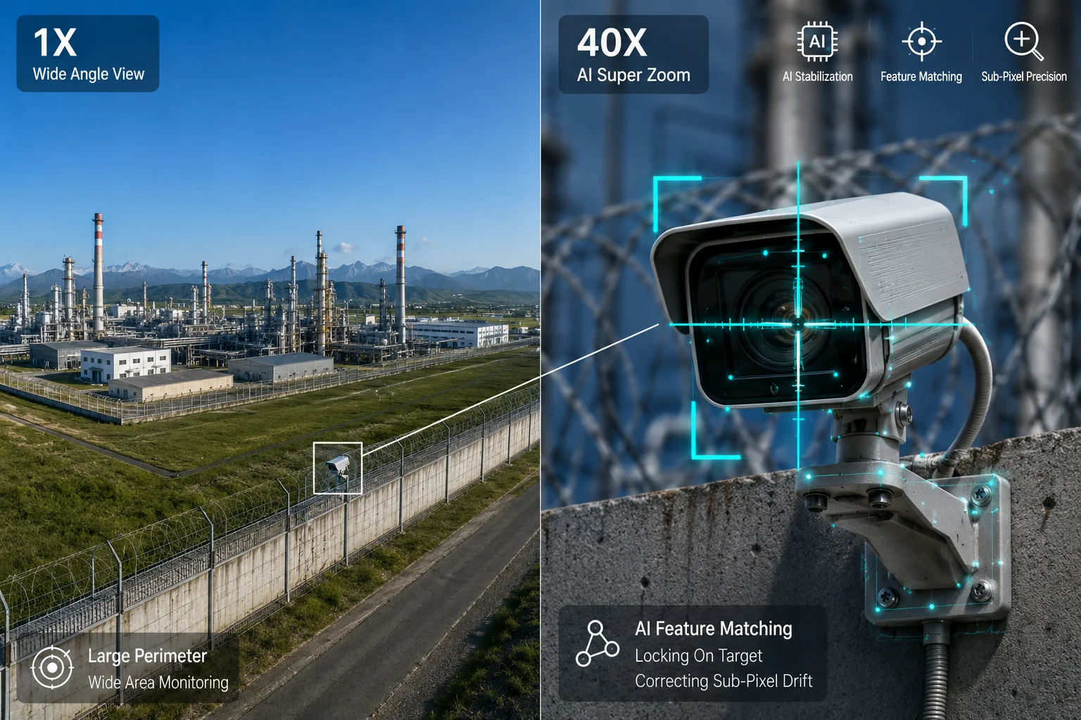 PTZ accuracy at 40X optical zoom
The Math Behind Visual Magnification of Error
Let me put real numbers on this. A typical 40X PTZ camera has a horizontal field of view (HFOV) of about 60° at 1X and about 1.5° at 40X.
At 1X (HFOV = 60°):
- A 0.1° error = 0.17% of the frame width
- On a 1920-pixel-wide image, that’s about 3 pixels
- Completely invisible to the human eye
At 40X (HFOV = 1.5°):
- A 0.1° error = 6.7% of the frame width
- On a 1920-pixel-wide image, that’s about 128 pixels
- Very noticeable — your target has shifted significantly
This is pure geometry. No amount of mechanical precision can change this relationship. The only solution is to either achieve much better than 0.1° mechanical accuracy (which we do, at 0.05° average), or add a secondary correction layer.
Our Visual Lock-In System
After the mechanical positioning is complete, our camera performs one additional step at high zoom levels:
- The system stores a reference image of the preset view (captured when you first set the preset).
- On each return, it captures the current frame at the preset position.
- An AI algorithm compares key feature points between the reference and current frame.
- If any pixel-level offset is detected, the camera makes a micro-adjustment (often just 0.01° or 0.02°) to align the frames perfectly.
This visual correction only activates when zoom is above 20X. Below that, the mechanical accuracy alone is sufficient.
Real-World Impact at Different Zoom Levels
| Zoom Level | HFOV | 0.05° Error (Pixels) | 0.1° Error (Pixels) | Visual Lock-In Active |
|---|---|---|---|---|
| 1X | 60° | ~1.6 px | ~3.2 px | No |
| 10X | 6° | ~16 px | ~32 px | No |
| 20X | 3° | ~32 px | ~64 px | Yes |
| 30X | 2° | ~48 px | ~96 px | Yes |
| 40X | 1.5° | ~64 px | ~128 px | Yes |
Limitations to Be Aware Of
I want to be transparent here. The visual lock-in system has requirements:
- The scene must have stable reference features (buildings, poles, road markings). A preset pointing at open water or a blank wall won’t have enough features to match.
- Lighting changes (day vs. night) can affect matching. The system stores both a day and night reference image to handle this.
- If the scene itself changes dramatically (a building is demolished, a tree grows), you’ll need to update the preset reference image.
For David’s typical deployments — perimeter security, construction sites, critical infrastructure — there are always plenty of stable features in the scene. This system works reliably in those environments.
Conclusion
Physical deviation below 0.1° is achievable and maintainable long-term through micro-step drive, closed-loop encoders, and AI visual correction. The mechanics hold accuracy. The software guarantees it. If you need to validate these numbers for your specific project, reach out — I’ll share our full test report.
1. Optical encoders offer high-resolution position sensing by reading incremental marks on a disc, critical for sub-0.1° feedback. ↩︎ 2. Worm gear drives provide high torque and self-locking, while zero-backlash design eliminates mechanical play that could cause positioning errors. ↩︎ 3. S-curve deceleration reduces mechanical stress and overshoot by smoothly ramping down motor speed as the camera approaches its target position. ↩︎ 4. ONVIF is a global standard for IP-based security devices; its commands allow remote triggering of PTZ self-calibration from VMS or third-party software. ↩︎ 5. Mechanical limit stops are physical endpoints of pan and tilt travel; the camera uses them as known references during self-calibration to reset encoder values. ↩︎ 6. Encoder counts are the digital pulses generated by an optical encoder; they are converted to angular degrees to track and correct PTZ positions. ↩︎ 7. Milestone is a leading VMS platform that integrates with ONVIF-compliant PTZ cameras for seamless preset management and calibration. ↩︎ 8. Sub-pixel accuracy goes beyond single-pixel resolution by interpolating between pixels, essential for fine alignment in high-zoom surveillance. ↩︎