
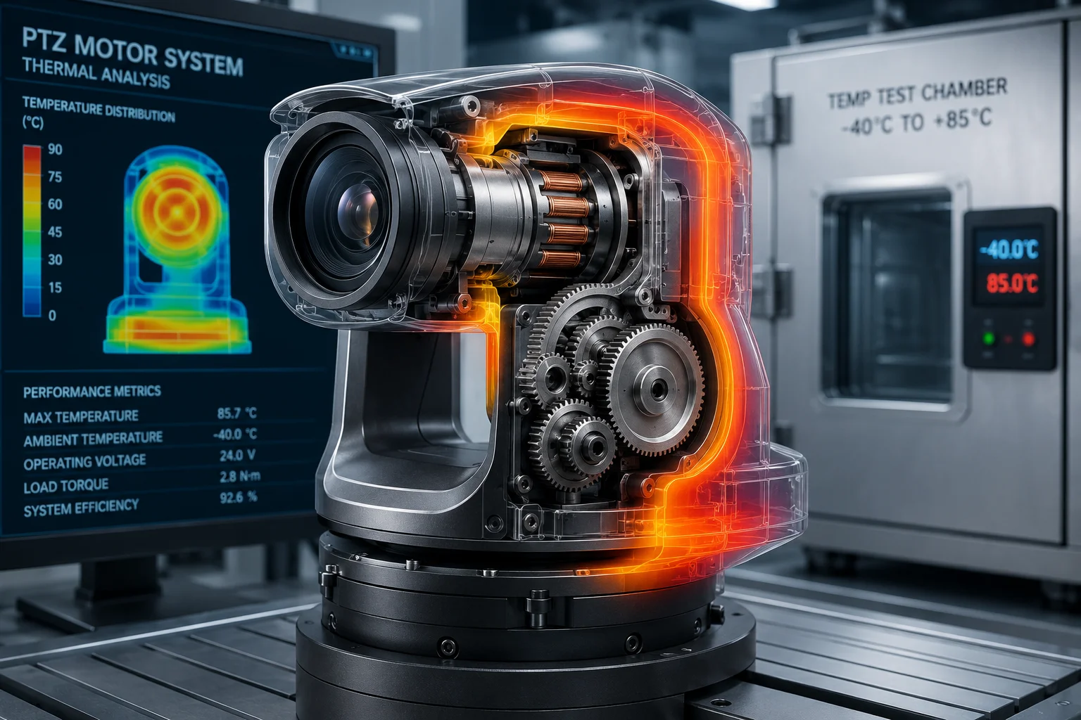
I’ve seen stepper motors fail in the field after just one summer. The root cause is almost always the same: no thermal management plan for high ambient temperatures.
At 50°C (122°F), stepper motors operate near the critical point of their insulation class. Without proper current control logic and heat dissipation design, the motor winding lifespan drops fast. Industrial-grade controllers use adaptive current scaling, PWM optimization, and physical thermal bridging to keep motors alive in extreme heat.
 stepper motor heat dissipation current control logic 50 degrees
Below, I’ll break down the exact logic and hardware design that keeps PTZ stepper motors running reliably when the air itself is already hot enough to cook electronics. Each section answers a specific question I hear from system integrators working in places like Texas, the Middle East, and Southeast Asia.
Table of Contents
Does the Motor Controller Use “Smart Current Scaling” to Reduce Heat When the PTZ Is Idle?
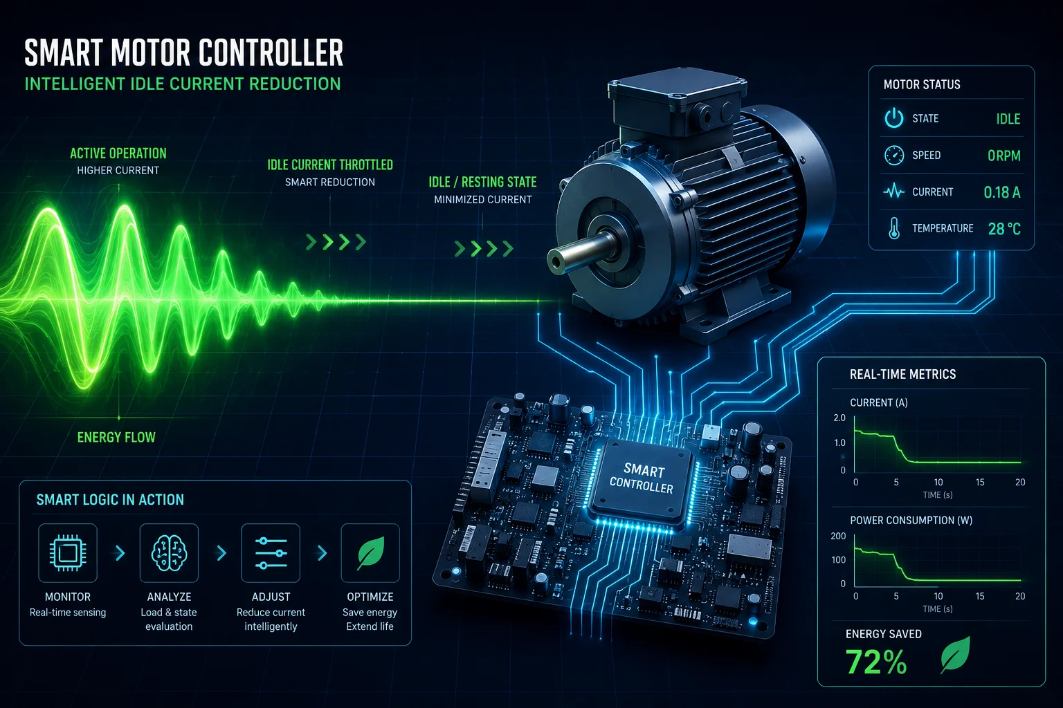
Most of the heat damage I’ve seen in the field happens not during motion, but when the motor is sitting still. People forget that a stepper motor draws holding current even when it’s not moving.
Yes. Industrial PTZ controllers use automatic idle current reduction. When the motor stops moving for 100–500ms, the driver cuts current to 30%–50% of the running value. This single feature prevents the most common cause of thermal failure: heat buildup during standstill.
 smart current scaling PTZ idle stepper motor
Why Idle Current Is the Silent Killer
A stepper motor generates heat through copper loss. The formula is simple: $P = I^2R$. Power loss equals current squared times resistance. This means if you cut the current in half, you reduce heat generation by 75%. That’s a massive difference when the motor sits idle for hours between patrol scans.
In a typical PTZ surveillance deployment, the camera spends 80%–90% of its time in a fixed position. During that time, the motor still needs some current to hold its position against wind load. But it does not need full running current. Smart current scaling solves this by using a timer-based step-down logic:
The Step-Down Logic Flow
- Motor completes its last commanded move.
- A timer starts (typically 100–500ms, configurable).
- If no new move command arrives, the driver reduces phase current to the preset idle level.
- If a new command arrives, current ramps back to full in under 10ms.
This logic is built into most modern stepper drivers like the TMC22092 or TMC5160 from Trinamic3. The key parameter is called “TPOWERDOWN4” — the delay before current reduction kicks in.
Current Scaling Settings for 50°C Environments
| Parameter | Standard Setting (25°C) | Recommended Setting (50°C) | Reason |
|---|---|---|---|
| Running Current | 100% of rated | 70%–85% of rated | Leave thermal headroom |
| Idle Current | 50%–70% of rated | 30%–50% of rated | Prevent standstill heat buildup |
| Power-Down Delay | 500ms | 100–200ms | Reduce idle time at full current |
| Current Ramp-Up Time | 10ms | 10ms | No change needed for responsiveness |
Load-Adaptive Current (Closed-Loop Systems)
For PTZ systems with an encoder on the motor shaft, the controller can do something even smarter. It measures the actual torque demand in real time. If the wind is calm and the camera is light, the controller only sends the current the motor actually needs. This is called load-adaptive current control5.
In a 50°C environment, this approach can reduce average power consumption by 30%–40% compared to open-loop systems that always run at maximum current. The trade-off is cost — you need an encoder and a closed-loop driver. But for a system that must survive 10 years on a pole in direct sunlight, the investment pays for itself in avoided truck rolls.
How Does the System Prevent Motor “Thermal Drift” from Affecting Tracking Accuracy in Mid-Summer?
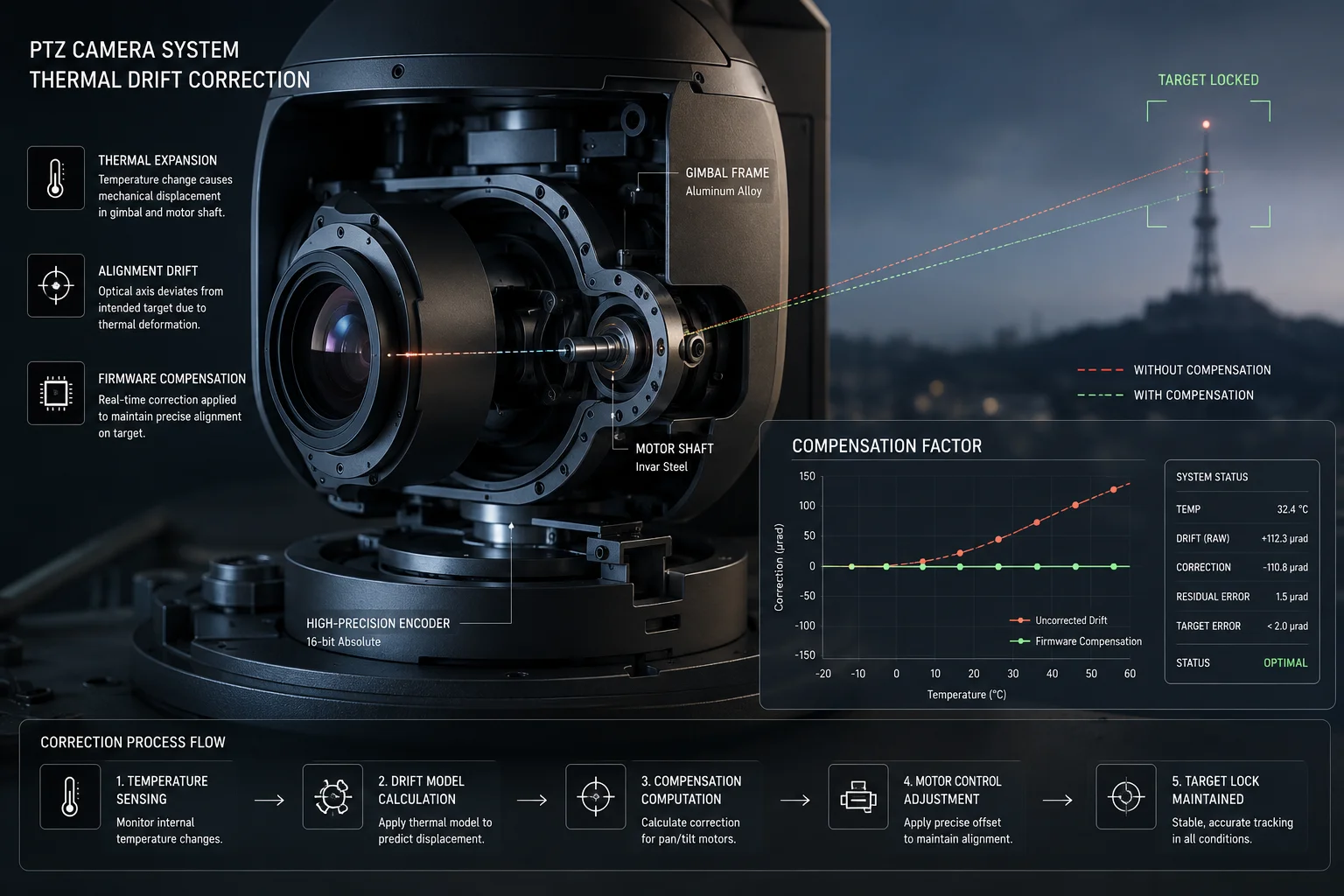
I’ve had integrators tell me their PTZ cameras slowly lose pointing accuracy as the day heats up. They recalibrate in the morning, and by 2 PM the presets are off by a few tenths of a degree. That’s thermal drift.
Thermal drift6 happens because heat changes the physical dimensions of motor components and the magnetic properties of the rotor. To prevent this, industrial PTZ systems use encoder-based closed-loop correction7, temperature-compensated firmware, and mechanical designs that constrain thermal expansion to predictable axes.
 thermal drift stepper motor tracking accuracy PTZ
What Causes Thermal Drift in Stepper Motors
When a stepper motor heats up from 25°C to 90°C (which is common at 50°C ambient under load), several things change:
- Winding resistance increases. Copper has a positive temperature coefficient of about 0.39% per °C. A 65°C rise means resistance goes up by roughly 25%. This reduces available torque at the same voltage.
- Magnet strength decreases. Neodymium magnets lose about 0.11% of their field strength per °C. At 90°C, the rotor magnets are about 7% weaker than at room temperature.
- Mechanical expansion. The aluminum housing expands. The steel shaft expands at a different rate. Bearing preload changes. All of this introduces micro-play in the gear train.
How Firmware Compensates
Modern PTZ controllers store a temperature-vs-offset lookup table in firmware. Here’s how the compensation loop works:
- A thermistor on the motor body reports temperature every 500ms.
- Firmware looks up the expected positional offset for that temperature.
- The controller applies a correction factor to all preset positions.
- If the system has an encoder, it also cross-checks the actual shaft angle against the commanded angle.
Mechanical Design Choices That Reduce Drift
The best approach is to minimize drift at the hardware level so firmware has less work to do:
- Matched thermal expansion materials. Use steel gears with steel shafts, not mixed aluminum-steel assemblies.
- Preloaded bearings. Spring-loaded angular contact bearings maintain consistent play across a wide temperature range.
- Short gear trains. Every gear mesh is a source of backlash that gets worse with heat. Fewer gears means less accumulated error.
Drift Budget Table
| Source of Drift | Magnitude at 90°C Motor Temp | Mitigation |
|---|---|---|
| Winding resistance change | Indirect (torque loss, not position) | Closed-loop current boost |
| Magnet weakening | ~0.05° pointing error | Encoder correction |
| Housing thermal expansion | ~0.02° per axis | Matched materials |
| Gear backlash increase | ~0.1° worst case | Preloaded anti-backlash gears |
| Total uncompensated drift | ~0.17° | — |
| After firmware correction | <0.03° | Encoder + lookup table |
For a 38X zoom camera at maximum telephoto, 0.17° of drift moves the image center by several meters at 500m range. That’s enough to lose a tracked target. After compensation, 0.03° keeps the target well within the frame.
Is There an Internal Thermistor on the Motor to Trigger a Safety Shutdown at Critical Temperatures?
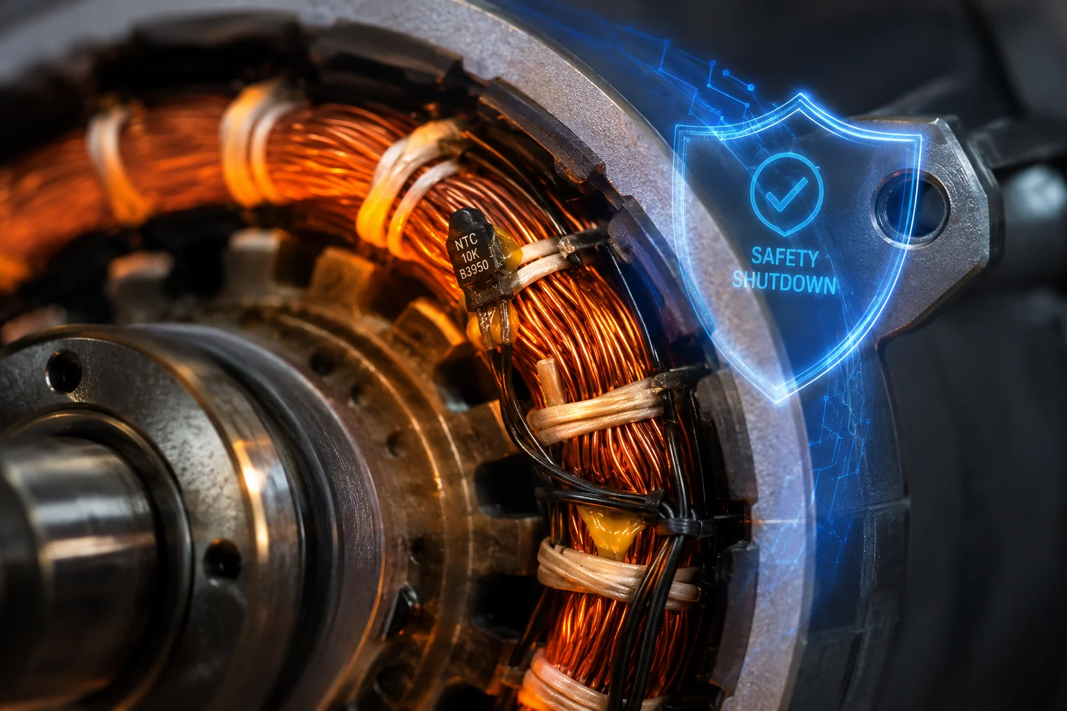
I always ask this question when evaluating a new motor supplier. If the answer is “no,” I walk away. A motor without thermal protection in a 50°C environment is a fire risk.
Yes, industrial-grade stepper motors designed for outdoor PTZ use include an embedded NTC thermistor8 (typically 10kΩ at 25°C) bonded directly to the stator winding. When the winding temperature reaches 130°C (Class B) or 155°C (Class F), the controller triggers a staged response: first current derating9, then a controlled shutdown if temperature keeps rising.
 thermistor stepper motor safety shutdown temperature
Why External Temperature Sensing Is Not Enough
Some cheaper systems only measure the driver board temperature or the ambient air temperature. This is a problem. The hottest point in the system is always the motor winding itself. The winding can be 40°C–60°C hotter than the motor case surface. By the time the case feels dangerously hot to touch, the winding insulation is already degrading.
An embedded thermistor sits inside the stator slot, in direct thermal contact with the copper wire. It reads the actual winding temperature with only 2–3 seconds of thermal lag. This gives the controller enough time to react before damage occurs.
The Staged Thermal Protection Logic
A well-designed system does not just cut power when things get hot. It uses a graduated response:
Stage 1: Soft Derating (Warning Zone)
- Trigger: Winding temperature reaches 110°C (Class B) or 135°C (Class F).
- Action: Controller reduces maximum current by 20%. Motor slows down but keeps working.
- Notification: System logs a thermal warning. If connected to a VMS, it sends an alert.
Stage 2: Hard Derating (Danger Zone)
- Trigger: Temperature continues rising to 125°C (Class B) or 150°C (Class F).
- Action: Current drops to 50%. Only slow, essential movements are allowed.
- Notification: Critical alarm sent. System recommends operator intervention.
Stage 3: Controlled Shutdown (Emergency)
- Trigger: Temperature hits 130°C (Class B) or 155°C (Class F).
- Action: Motor current goes to zero. Mechanical brake engages (if equipped). System enters safe state.
- Recovery: Motor must cool below 100°C before restart is allowed.
Choosing the Right Insulation Class
For any PTZ system deployed where ambient temperatures reach 50°C, I strongly recommend Class F insulation1. Here’s why:
- At 50°C ambient, a motor running at 85% current will have a winding temperature rise of about 60°C–70°C.
- Total winding temperature: 50 + 70 = 120°C.
- Class B limit is 130°C. That leaves only 10°C of margin. One hot day with no wind, and you’re in the shutdown zone.
- Class F limit is 155°C. That gives you 35°C of margin. The system can handle temporary overloads, solar heat gain on the housing, and aging-related efficiency loss without triggering protection.
The cost difference between Class B and Class F motors is typically 10%–15%. For a system that costs $200+ to service in the field, this is an obvious investment.
Can I Monitor the Real-Time Motor Temperature and Power Draw Through the Web Diagnostic UI?
When I deploy systems in remote locations, I need to see what’s happening without driving out there. Temperature and power data should be available from my desk.
Yes. Professional PTZ cameras with industrial-grade motor systems expose real-time thermal and electrical data through their web diagnostic interface. You can monitor winding temperature, driver board temperature, phase current, bus voltage, and cumulative thermal stress — all from a browser or through SNMP10/API integration with your VMS13.
 web diagnostic UI motor temperature power monitoring PTZ
What Data Points Should Be Available
Not all web interfaces are equal. A basic consumer PTZ might show you “device temperature” as a single number. That’s not useful for predictive maintenance. Here’s what an industrial-grade diagnostic UI should expose:
Essential Telemetry Parameters
| Parameter | Update Rate | Purpose |
|---|---|---|
| Motor winding temperature (pan) | Every 1s | Detect thermal overload before shutdown |
| Motor winding temperature (tilt) | Every 1s | Tilt motor often runs hotter due to gravity load |
| Driver board temperature | Every 5s | Monitor electronics health |
| Phase current (pan motor) | Every 1s | Detect mechanical binding or overload |
| Phase current (tilt motor) | Every 1s | Same as above |
| Bus voltage | Every 5s | Detect power supply sag under load |
| Cumulative thermal hours | Daily log | Track insulation aging over time |
| Thermal event count | Event-based | Count how many times derating triggered |
Integration with Monitoring Platforms
For large deployments with 50–500+ cameras, nobody watches individual web UIs. The data needs to flow into a central platform. The standard methods are:
- SNMP traps and polling. The camera acts as an SNMP agent. Your NMS (like PRTG or Zabbix) polls temperature OIDs and triggers alerts when thresholds are crossed.
- [REST API11. The camera exposes a JSON endpoint (e.g.,
/api/v1/diagnostics/thermal) that your custom dashboard can query. - [ONVIF12 analytics events. Some systems publish thermal alerts as ONVIF analytics events, which any compatible VMS can subscribe to.
Using Thermal Data for Predictive Maintenance
The real value of this data is not just avoiding shutdowns. It’s predicting failures before they happen. Here’s how:
If you log motor temperature over months, you’ll notice a trend. A healthy motor in a 50°C environment might stabilize at 105°C during a patrol cycle. If that number creeps up to 115°C over six months with no change in ambient conditions, something is wrong. Maybe a bearing is wearing out and adding friction. Maybe dust has clogged the heat sink. Maybe the gear grease has dried out.
By catching this trend early, you can schedule maintenance during a planned visit instead of responding to an emergency failure. For remote sites where a truck roll costs $500–$1,000, this kind of visibility pays for itself after preventing a single unplanned service call.
I also recommend setting up automated alerts at two levels: a “watch” alert at 80% of the shutdown threshold (so you have days or weeks to plan), and a “critical” alert at 90% (so you have hours to act).
Conclusion
At 50°C ambient, stepper motor survival depends on smart current scaling, thermal drift compensation, embedded thermistor protection, and remote monitoring. Choose Class F insulation, use closed-loop drivers, and always demand real-time thermal telemetry from your PTZ supplier.
1. Learn about motor insulation classes and the thermal limits of Class F (155°C) for high-temperature environments. ↩︎ 2. View the datasheet and features of the TMC2209 stepper motor driver from Trinamic. ↩︎ 3. Explore Trinamic’s portfolio of stepper motor drivers and motion control technologies. ↩︎ 4. Understand the TPOWERDOWN parameter that controls idle current reduction timing in Trinamic drivers. ↩︎ 5. Discover how load-adaptive current control reduces power consumption by matching torque to demand. ↩︎ 6. Learn how thermal expansion and material property changes cause positional drift in motors. ↩︎ 7. Understand how encoder feedback compensates for thermal effects and improves stepper motor accuracy. ↩︎ 8. Get an overview of NTC thermistors and their use in temperature sensing for motor windings. ↩︎ 9. Learn about derating as a thermal management strategy to protect electronic components. ↩︎ 10. Understand how SNMP enables remote monitoring and management of network devices like PTZ cameras. ↩︎ 11. Learn about RESTful APIs and how they enable programmatic access to device diagnostics. ↩︎ 12. Explore the ONVIF standard for interoperability of IP-based security devices. ↩︎ 13. Learn about Video Management Systems and how they integrate with camera telemetry. ↩︎