
I have seen PTZ cameras drift off target after just a few hundred preset cycles. That small shift can cost you an entire project.
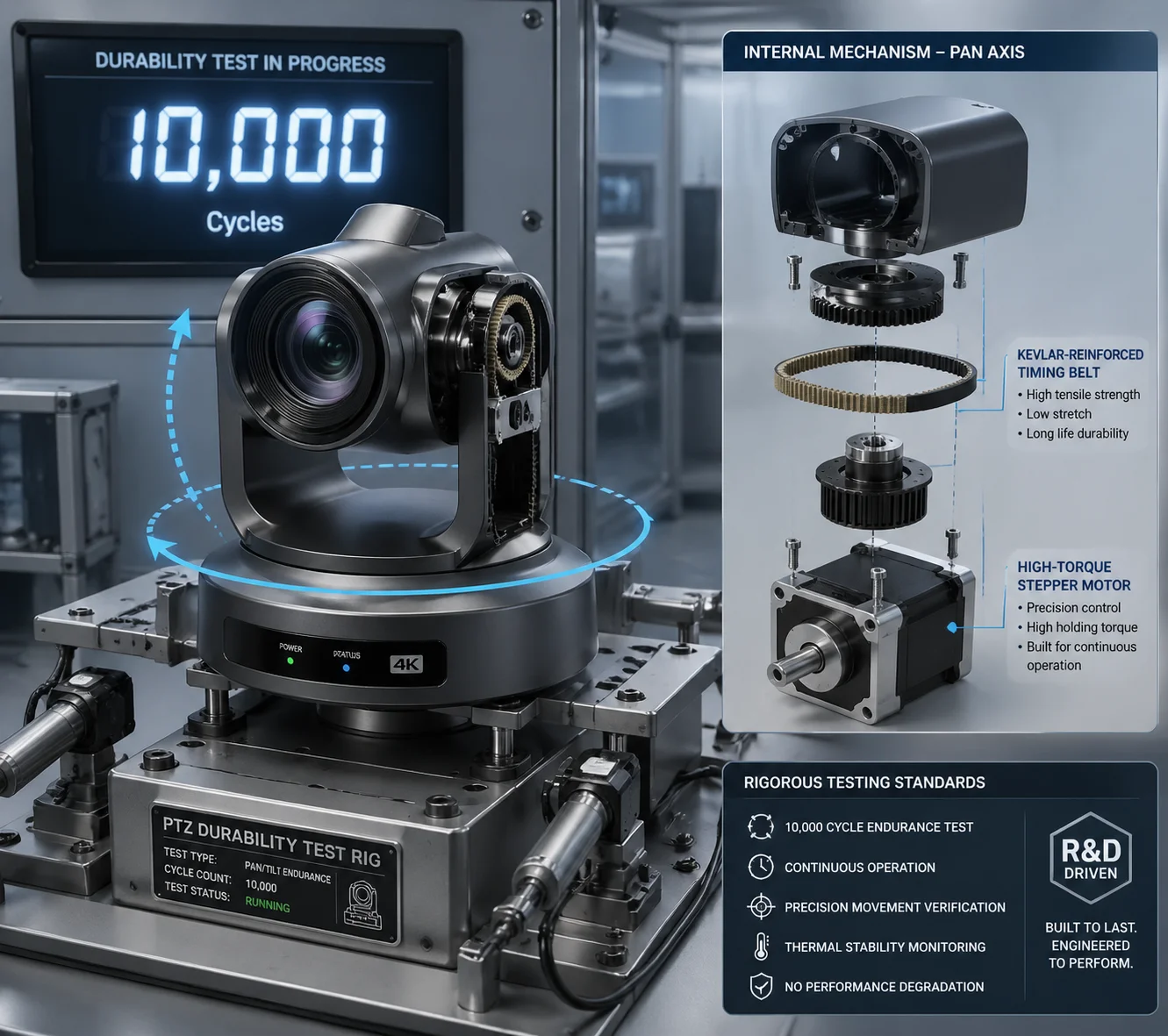
We keep preset deviation under ±0.1° by combining 256 micro-step motor drivers, Kevlar-reinforced belt transmission, S-curve motion algorithms, and photo-interrupter zero-point calibration. These four layers work together so every preset returns to the exact same spot, even after thousands of cycles.
 PTZ camera preset positioning accuracy test
In this article, I will walk you through each piece of this system. I will also show you a practical test method you can use to verify 0.1° accuracy yourself — before you sign off on any shipment. Let’s get into it.
Table of Contents
Will My Camera Lose Its “Home” Position After 10,000 Cycles of Panning and Tilting?
This is the question that keeps every integrator up at night. You install 50 cameras on a highway, and six months later, half of them are pointing at the wrong lane.
No. Our PTZ cameras do not lose their home position after 10,000 cycles. Every unit passes a 3,000-cycle stress test before it ships. The physical photo-interrupter resets the zero point on every power-up, so electronic drift never accumulates into a permanent offset.
 PTZ camera home position cycling test
Why Do Presets Drift in the First Place?
Most preset drift comes from three sources: motor step loss, belt stretch, and electronic counter errors. Let me break each one down.
Motor step loss happens when a stepper motor 1 moves too fast and skips a step. Each skipped step adds a tiny angle error. Over hundreds of cycles, these errors stack up. The camera thinks it is at 90°, but it is actually at 90.3°. On a 40X zoom, that 0.3° means your target is completely off-screen.
Belt stretch is a mechanical problem. Cheap rubber belts expand when they get hot. In a desert or a rooftop install, the housing temperature can reach 60°C or higher. The belt gets longer, the gear ratio changes slightly, and the preset shifts.
Electronic counter errors are the sneakiest. The controller counts motor pulses to track position. But electrical noise, power glitches, or firmware bugs can corrupt that counter. The camera has no way to know it is wrong — unless it has a physical reference point to check against.
How We Solve Each Problem
| Drift Source | Our Solution | Result |
|---|---|---|
| Motor step loss | 256 micro-step driver with current control | Minimum step angle < 0.05°, virtually no skipping |
| Belt stretch | Kevlar-reinforced timing belt | Near-zero thermal expansion, even at 60°C |
| Electronic counter error | Photo-interrupter zero-point reset on every boot | Accumulated errors cleared automatically |
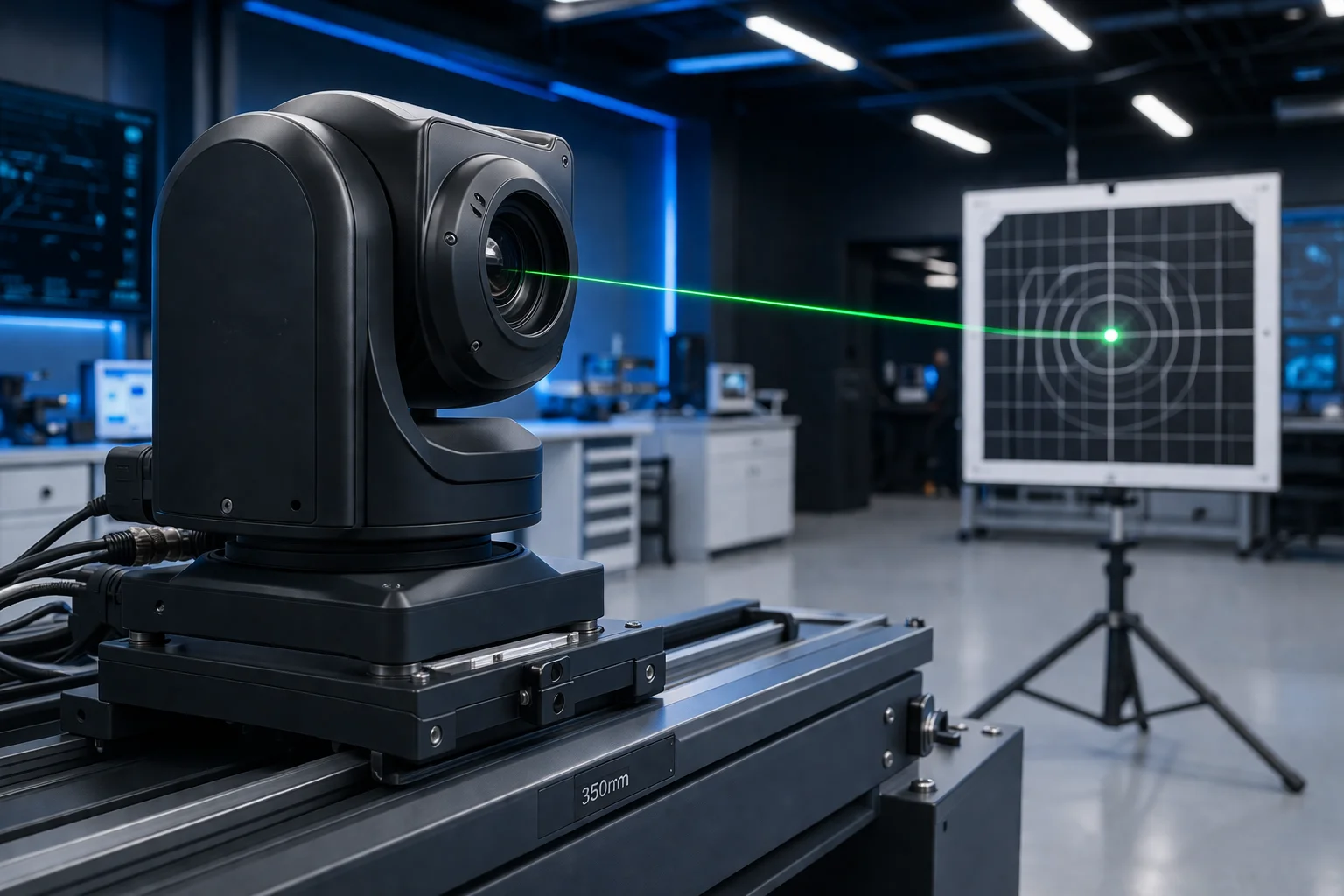
The 3,000-Cycle Factory Test
Before any unit leaves our factory, we mount a laser pointer on the PTZ head. We program it to cycle through 256 presets continuously for 24 hours — that is over 3,000 full cycles. A fixed target board sits at the far end of the test room. We measure the laser dot position after every cycle. If the dot drifts more than the equivalent of 0.1° on any single preset, that unit fails. It does not ship.
This is not a sample test. We run it on every single camera. David, if you want, we can send you the test report with photos of the laser target for your specific batch.
How Does the High-Precision Encoder Prevent the Preset From “Drifting” Over Time?
I have talked to integrators who replaced entire camera fleets after two years because the presets had drifted so far that the cameras were useless. That is a massive waste of money.
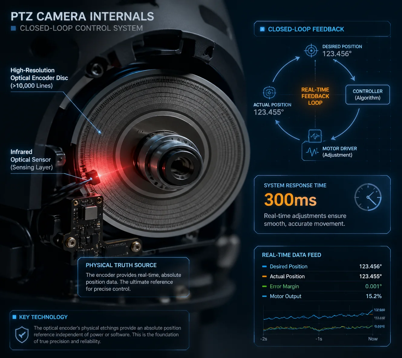
Our high-precision optical encoder acts as a physical truth source. It continuously monitors the actual angular position of the pan and tilt axes. If the real position deviates from the commanded position — even by a fraction of a degree — the system corrects it within 300 milliseconds.
 High-precision optical encoder for PTZ camera
Open-Loop vs. Closed-Loop: Why It Matters
Most budget PTZ cameras use an open-loop system. The controller sends a command: “Move 500 steps to the right.” The motor moves 500 steps. The controller assumes the camera is now at the correct angle. But it never checks.
This is like driving with your eyes closed. You turn the steering wheel 30 degrees and hope you are in the right lane. It works for a while. Then it doesn’t.
A closed-loop system adds a sensor that constantly reads the actual position. If the motor overshoots by 2 steps, the sensor sees it and the controller sends a correction. This is the difference between hoping and knowing.
How Our Encoder System Works
Our encoder system has two layers:
Layer 1: Photo-interrupter zero-point sensor. This is a simple but critical component. A small optical gate sits at a fixed physical position on both the pan and tilt axes. Every time the camera powers on, it rotates until it hits this gate. That is the absolute zero reference. All preset positions are calculated from this point. This means that even if the electronic counter was corrupted during a power outage, the camera will find its true zero on the next boot. The accumulated error is gone.
Layer 2: High-resolution optical disc (optional for high-end projects). For critical installations — border surveillance, airport perimeters, highway monitoring — we offer an optional high-resolution optical encoder 2 disc. This disc has thousands of precisely etched lines. A sensor reads these lines in real time as the camera moves. The result is continuous, absolute position feedback.
What Happens When Wind Pushes the Camera?
This is a real-world scenario that most spec sheets ignore. A strong gust of wind hits the camera housing. The head moves 0.2° off its preset. Without an encoder, the camera does not know it moved. It just sits there, pointing at the wrong spot.
With our optical encoder, the system detects the displacement instantly. Within 300 milliseconds, the motor activates and pushes the head back to the correct position. The operator never even sees it happen.
| System Type | Detects External Disturbance? | Self-Corrects? | Long-Term Drift |
|---|---|---|---|
| Open-loop (no encoder) | No | No | Accumulates over time |
| Zero-point only | No (only on reboot) | Only on reboot | Resets on each power cycle |
| Full optical encoder | Yes, in real time | Yes, within 300 ms | Effectively zero |
Can I Perform a Remote Calibration if the Preset Accuracy Starts to Degrade?
You have 200 cameras spread across three states. One of them starts showing preset drift. You cannot send a technician to every site just to recalibrate a camera.
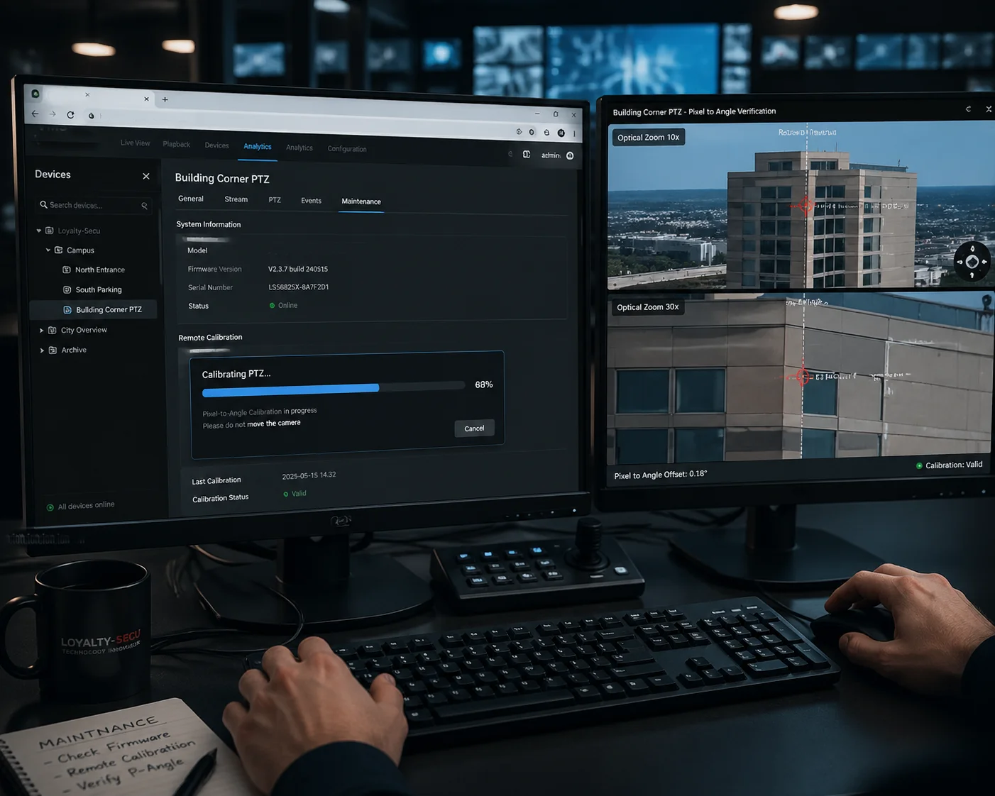
Yes. You can trigger a remote zero-point recalibration through the web interface or your VMS. The camera will automatically run its homing routine, find the physical zero-point sensor, and reset all preset references. No on-site visit required.
 Remote PTZ camera calibration interface
When Should You Recalibrate?
In most cases, you should never need to manually recalibrate. The camera does it automatically on every power-up. But there are a few situations where a manual remote recalibration makes sense:
- After a firmware update that changes motor control parameters.
- After the camera has been running continuously for several months without a reboot.
- After a known physical event — like a severe storm, an earthquake, or someone bumping the camera during maintenance.
- When you notice on your VMS that a preset is slightly off from where it should be.
How the Remote Calibration Process Works
The process is simple. You log into the camera’s web interface. You go to the PTZ settings page. You click “Home Reset” or “Zero-Point Calibration.” The camera will pan and tilt until it finds the photo-interrupter gate on each axis. This takes about 10 seconds. After that, all 256 presets are recalculated from the new zero reference.
You can also schedule this automatically. For example, you can set the camera to recalibrate at 3:00 AM every Sunday. During that 10-second window, the camera briefly moves to find its zero point, then returns to its patrol or preset. For most projects, this is more than enough to keep drift at zero.
A Practical Verification Method You Can Use
After recalibration, how do you know it actually worked? Here is a method I recommend to all our integrator partners.
Pick a preset that points at a fixed, high-contrast feature — a building corner, a pole, a painted line. Take a screenshot. This is your reference image. Note the pixel coordinates of that feature.
After recalibration, call the same preset. Take another screenshot. Compare the pixel coordinates. If the feature has moved less than 3 pixels (at a typical 60° HFOV on a 1080p sensor), you are within 0.1°.
You can do this from your desk. No ladder. No truck roll. No wasted afternoon.
Pixel-to-Angle Conversion Reference
| Horizontal FOV | Resolution | Degrees per Pixel | Pixels Allowed for 0.1° |
|---|---|---|---|
| 60° | 1920 px | 0.031° | ~3.2 px |
| 30° | 1920 px | 0.016° | ~6.4 px |
| 3° (40X zoom) | 1920 px | 0.0016° | ~64 px |
Notice something interesting in that table. At 40X zoom, the FOV is very narrow — around 3°. That means each pixel covers a much smaller angle. So 0.1° of drift would show up as a 64-pixel shift on screen. That is huge. You would see it immediately. This is why mechanical precision matters most at high zoom levels.
Is the 0.1-Degree Accuracy Maintained Even at the Maximum 40X Optical Zoom?
This is the question that separates marketing claims from engineering reality. Any camera can hit 0.1° at wide angle. The real test is at 40X zoom, where every tiny error is magnified.
Yes. The 0.1° mechanical accuracy is a property of the pan-tilt mechanism, not the lens. It stays the same regardless of zoom level. But at 40X zoom, the visual impact of even 0.05° of error becomes very obvious — which is exactly why our mechanical precision must be this tight.
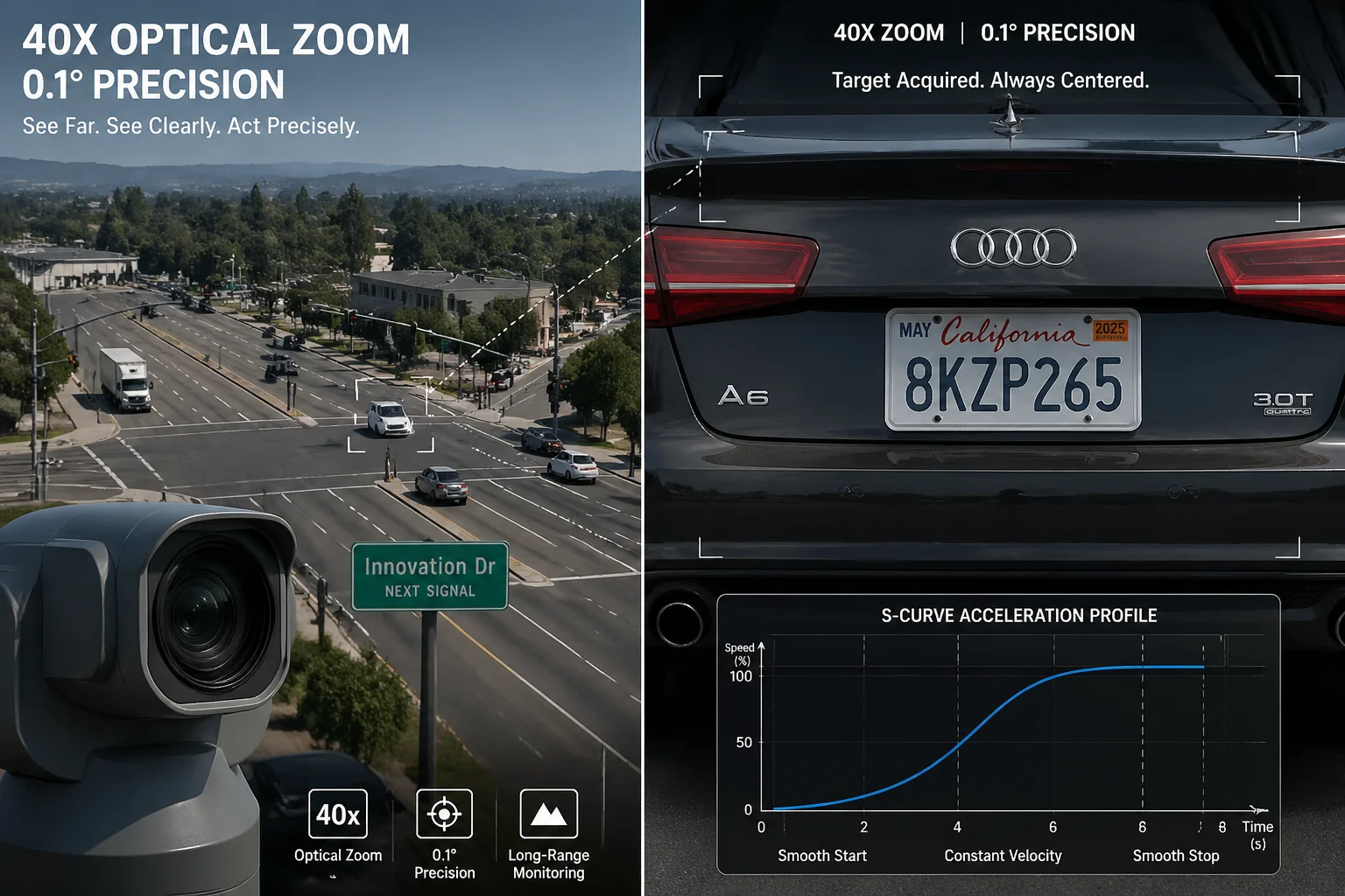 PTZ camera 40X optical zoom preset accuracy
Why Zoom Magnifies the Problem
Let me explain this with a simple example. At wide angle (60° FOV), your camera sees a 100-meter-wide area at 500 meters distance. A 0.1° error shifts the image center by about 0.87 meters. You probably would not even notice.
At 40X zoom, the FOV shrinks to roughly 1.5°. Now your camera sees only a 13-meter-wide area at the same distance. That same 0.1° error still shifts the center by 0.87 meters. But now 0.87 meters is a significant portion of your entire field of view. A person’s face that was centered is now at the edge of the frame — or gone entirely.
This is why we say: preset accuracy is not a zoom specification. It is a mechanical specification. The motor, the belt, the encoder — they do not know or care what zoom level the lens is at. They just need to put the head at the right angle. Every time.
The Engineering Behind Consistent Accuracy
Three things make this possible at our factory:
256 micro-step motor control. By dividing each 1.8° motor step into 256 micro-steps, we achieve a minimum controllable angle of about 0.007°. This gives us more than 14 times the resolution we need for 0.1° accuracy. That margin is intentional. It means we can still hit 0.1° even if a few micro-steps are lost due to friction or load.
S-curve acceleration and deceleration. When the camera moves to a preset, it does not just slam to a stop. It follows an S-shaped speed profile — slow start, smooth acceleration, gradual deceleration, soft stop. This eliminates the mechanical shock that causes overshoot. Without S-curve control, a fast-moving PTZ head can overshoot its target by 0.2° to 0.5° before settling. With it, overshoot is effectively zero.
Dynamic wear compensation. Our firmware tracks how many cycles each axis has completed. As the cycle count increases, the algorithm applies a small correction factor to account for belt wear and bearing friction changes. This is not a fixed offset — it is a learned value that updates over the life of the camera. The result is that a camera with 50,000 cycles on it hits presets just as accurately as a brand-new unit.
How to Test This Yourself at 40X Zoom
If you are evaluating our cameras — or any PTZ camera — here is what I suggest:
- Set the camera to 40X zoom.
- Point it at a distant object with sharp edges (a sign, a window frame, a pole).
- Save that as Preset 1.
- Move the camera to a completely different position (Preset 2).
- Call Preset 1 again.
- Compare the image to your reference.
- Repeat 50 times.
If the target feature stays within 3 pixels on a 1080p image at 60° HFOV — or within the equivalent pixel count for your actual FOV — the camera passes. If it drifts, you have a problem. And you will know before you install a single camera on a pole.
Conclusion
Preset accuracy under 0.1° comes from tight hardware, smart algorithms, and physical self-calibration — not just a number on a spec sheet. Test it. Verify it. Then trust it.
1. Stepper motor open-loop control and inherent step loss risks. ↩︎ 2. Optical rotary encoder for absolute position feedback. ↩︎ 3. Kevlar-reinforced belt thermal expansion properties. ↩︎ 4. Photo-interrupter zero-point calibration circuit design. ↩︎ 5. 256 micro-step vs full-step torque and precision comparison. ↩︎ 6. S-curve motion profiling for mechanical shock reduction. ↩︎ 7. Dynamic wear compensation algorithm for long-term accuracy. ↩︎ 8. Pixel-to-angle conversion for preset verification tests. ↩︎ 9. Closed-loop vs open-loop PTZ motor control methods. ↩︎ 10. ONVIF PTZ service for remote calibration commands. ↩︎