
I once watched a 40X PTZ demo where the image jumped frame by frame like a slideshow. That moment told me smooth motion is everything.
Stepping motors eliminate the “stepped” look at 40X zoom by using microstepping technology that splits each physical step into 256 or more subdivisions, combined with S-curve acceleration profiles and closed-loop encoder feedback. These techniques together turn jerky, visible jumps into fluid, continuous camera movement that looks natural even at the narrowest telephoto angle.
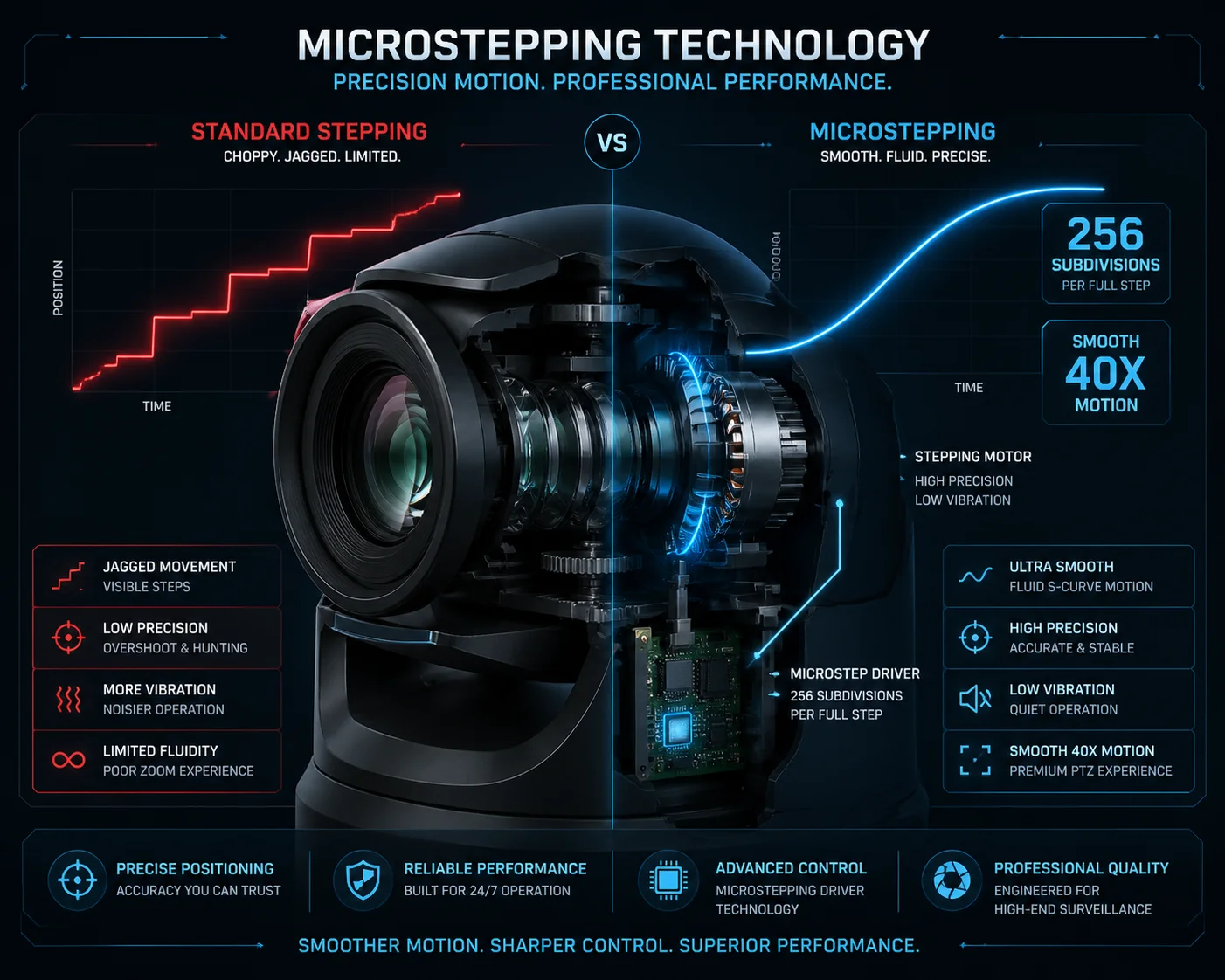 PTZ camera stepping motor smooth motion at 40X zoom
At Loyalty-Secu, we build 38X and 40X PTZ cameras every day. We have spent years tuning motor drivers, gear ratios, and firmware to solve this exact problem. Below, I will walk you through the four most common questions our clients ask about stepping motor performance at high zoom. Each answer goes deep into the engineering so you can write better specs and pick better suppliers.
Does Your Camera Use Micro-Stepping Technology for Ultra-Smooth Slow Panning?
I have seen too many PTZ cameras that claim “smooth pan” on the datasheet but deliver visible stutter at 30X and above. The gap between marketing and reality is huge.
Yes, our cameras use true microstepping with sine-wave current control at 1/128 or 1/256 subdivision. This breaks a standard 1.8° full step into thousands of tiny sub-steps, so the pan head moves in near-continuous rotation instead of jumping from one position to the next.
 PTZ microstepping motor driver sine wave current control
Why Full-Step Driving Fails at 40X
A standard two-phase stepper motor has a step angle of 1.8°. That means 200 steps per full revolution. If your gear ratio is 1:10, each output step is 0.18°. That sounds small. But at 40X zoom, the field of view is extremely narrow — often less than 2°. So a single 0.18° jump moves the image by roughly 9% of the entire frame. Your viewer sees a hard, visible snap.
Now compare that to 1/256 microstepping. Each output step becomes 0.18° ÷ 256 = 0.000703°. That is so small that even at 40X, the image shift per step is invisible to the human eye.
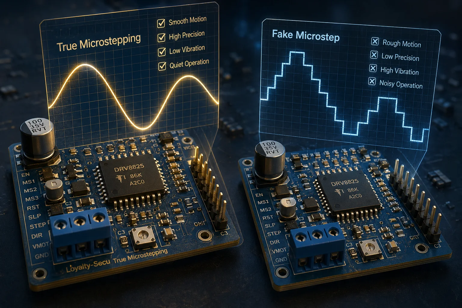
Real vs. Fake Microstepping
Not all microstepping is equal. Cheap drivers just change the number on a register but do not actually shape the current waveform. The result is what engineers call “fake subdivision.” The motor still vibrates and jumps because the current in each coil is not following a clean sine curve.
True microstepping requires:
- Sine-wave current profiling on both phases (Phase A = sin, Phase B = cos).
- High-resolution current sensing so the driver can hold each micro-position accurately.
- Low-noise PCB layout to prevent electrical interference from distorting the waveform.
| Feature | Cheap Driver (Fake Microstep) | Quality Driver (True Microstep) |
|---|---|---|
| Subdivision setting | 1/16 or 1/32 on paper | 1/128 or 1/256 verified |
| Current waveform | Rough staircase | Smooth sine wave |
| Vibration at low speed | High, audible hum | Very low, nearly silent |
| Image quality at 40X pan | Visible stutter | Smooth, continuous glide |
| Typical chip examples | Generic Chinese clones | TI DRV8825, TMC2209/5160 |
What to Ask Your Supplier
When you evaluate a PTZ from any factory, ask for two things:
- A slow-pan video recorded at maximum optical zoom. Play it back frame by frame. If you see discrete jumps, the microstepping is not working properly.
- The driver chip model and the actual subdivision ratio. A reputable factory will share this without hesitation.
At Loyalty-Secu, we provide these test videos as part of our standard sample evaluation process. We believe that if the motor performance cannot survive a video test, it should not ship.
Why Does the Image Look “Jerky” on Cheap PTZs When Following a Distant Person?
I had a client in Canada who bought 50 budget PTZ units for a pipeline project. At full zoom, the auto-tracking looked like the camera was having a seizure. He replaced all 50 within six months.
The jerky look comes from three combined problems: coarse step resolution that creates visible jumps, mechanical resonance that amplifies vibration at certain speeds, and abrupt start-stop commands that cause the lens assembly to shake. Cheap PTZs cut costs on all three areas, so the problem multiplies at long focal lengths.
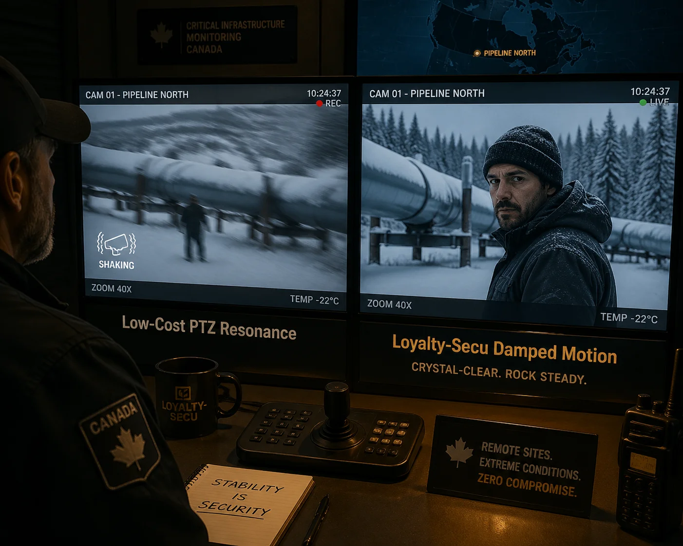 Jerky PTZ image vs smooth PTZ image comparison at high zoom
Problem 1: Coarse Step Resolution
As I explained above, a full-step or half-step driver at 40X zoom produces image jumps that are clearly visible. But cheap PTZs go even further in the wrong direction. They often use motors with 7.5° step angles (only 48 steps per revolution) because those motors cost less. Even with 1/16 microstepping, each output step is still far too large for telephoto work.
Problem 2: Resonance Zones
Every stepper motor has natural resonance frequencies. When the motor speed matches one of these frequencies, vibration spikes dramatically. In a cheap PTZ, the firmware does not know about these zones. It just runs the motor at whatever speed the joystick commands. If that speed happens to land in a resonance zone, the whole camera shakes.
Good firmware maps out the resonance zones during factory calibration and either skips through them quickly or avoids them entirely.
Problem 3: Hard Start and Hard Stop
A cheap controller sends a square-wave speed command: zero to target speed instantly, then target speed to zero instantly. This creates a torque spike at both ends. The camera head lurches forward, overshoots, and then bounces back. At 40X, this bounce is magnified into a violent image shake that can take a full second to settle.
How Quality PTZs Solve All Three
| Problem | Cheap PTZ Approach | Quality PTZ Approach |
|---|---|---|
| Step resolution | 7.5° motor, 1/8 microstep | 0.9° motor, 1/128+ microstep |
| Resonance | No resonance mapping | Firmware skips resonance zones |
| Start/stop | Square-wave command | S-curve or trapezoidal ramp |
| Damping | No mechanical damper | Inertia disc or silicone damper on shaft |
| Gear train | Plastic gears with backlash | Metal gears with anti-backlash spring |
The Real Cost of “Cheap”
My client in Canada learned this the hard way. The 50 cheap units cost him $8,000 upfront. But the replacement units, the labor to swap them on remote pipeline poles, and the lost contract credibility cost him over $40,000. When you buy PTZ cameras for serious projects, the motor system is not the place to save money.
Can I Adjust the Pan/Tilt Speed Dynamically Based on My Current Zoom Level?
I get this question at almost every trade show. The answer surprises many people because most PTZ cameras already have this feature — they just implement it badly.
Yes, professional PTZ cameras can and should link pan/tilt speed to the current zoom level automatically. This feature is called “proportional pan” or “zoom-speed coupling.” As the zoom increases, the firmware reduces the maximum pan and tilt speed so the image moves at a comfortable, watchable rate on screen.
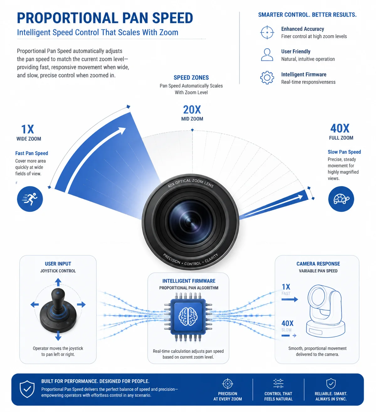 PTZ proportional pan speed linked to zoom level diagram
Why This Matters at 40X
At 1X wide angle, a pan speed of 100°/s feels normal. The scene sweeps across the screen at a comfortable pace. But at 40X, the same 100°/s would make the image blur into an unreadable streak. The field of view is 40 times narrower, so every degree of rotation moves the image 40 times more on screen.
To keep the on-screen motion speed constant, the pan speed must drop by a factor roughly proportional to the zoom ratio. At 40X, that means the maximum pan speed should be around 2.5°/s or less.
How the Firmware Handles This
The zoom motor reports its current position to the main controller. The controller looks up a speed-limit table that maps each zoom position to a maximum allowed pan/tilt speed. When the operator pushes the joystick, the controller caps the motor speed at the value from the table.
The Speed-Limit Table Concept
Here is a simplified example of what this table looks like inside the firmware:
| Zoom Level | Field of View (Horizontal) | Max Pan Speed | Max Tilt Speed |
|---|---|---|---|
| 1X | 58° | 120°/s | 90°/s |
| 10X | 5.8° | 12°/s | 9°/s |
| 20X | 2.9° | 6°/s | 4.5°/s |
| 30X | 1.9° | 4°/s | 3°/s |
| 40X | 1.45° | 2.5°/s | 2°/s |
What Happens Without Zoom-Speed Coupling
Without this feature, the operator must manually reduce joystick input at high zoom. This is tiring and imprecise. Most operators overshoot the target, then overcorrect, creating a back-and-forth wobble that looks unprofessional on recorded footage.
Going One Step Further: Adaptive Acceleration
At Loyalty-Secu, our firmware does not just cap the speed. It also adjusts the acceleration curve based on zoom level. At 40X, the S-curve ramp time is longer, so the camera eases into motion more gently. At 1X, the ramp is shorter for fast response. This dual adjustment — speed limit plus acceleration shaping — gives operators a consistent “feel” at every zoom level.
If you are writing a spec for your next PTZ purchase, include this line: “Pan/tilt speed shall automatically scale in inverse proportion to the optical zoom ratio, with S-curve acceleration adjusted per zoom level.” That single sentence will filter out most low-end products.
How Does the Motor Driver Minimize Vibration at the Narrowest Telephoto Angle?
I spent three months in 2022 working with our firmware team to kill a subtle 2-pixel vibration that only appeared at 38X and above. It turned out to be a resonance issue at a very specific pan speed. Fixing it taught me a lot.
The motor driver minimizes vibration at maximum telephoto by combining high-subdivision microstepping with active resonance avoidance, S-curve motion profiles, and mechanical damping. Together, these methods reduce torque ripple and prevent the motor from dwelling at speeds where its natural frequency causes oscillation.
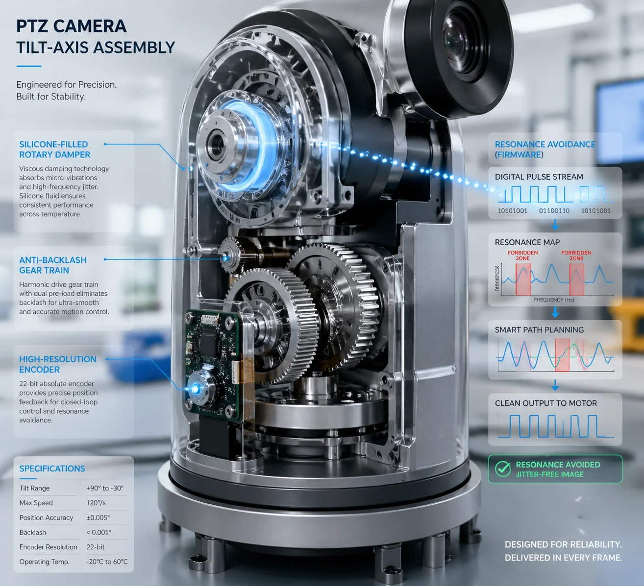 Stepper motor vibration damping system for PTZ camera
Understanding Torque Ripple
Every stepper motor produces a small fluctuation in torque as it moves from one step to the next. This is called torque ripple 1. At low zoom, this ripple is invisible because the field of view is wide. But at 40X, even a 0.001° oscillation translates into visible pixel jitter on screen.
Microstepping reduces torque ripple because the current transitions between steps are gradual, not abrupt. A 1/256 microstep driver produces torque ripple that is roughly 1/256th of the full-step ripple. That is usually small enough to be invisible even at 40X.
Active Resonance Avoidance
Stepper motors have two main resonance zones:
- Low-speed resonance — typically around 1-3 rev/s for small motors. This is the most dangerous zone for PTZ cameras because slow panning at high zoom often falls right into it.
- Mid-range instability — a broader zone where the motor can lose synchronization.
Our firmware measures the resonance profile of each motor model during development. Then it programs “forbidden zones” into the speed controller. When the target speed falls inside a forbidden zone, the controller either jumps through it quickly during acceleration or shifts to a nearby safe speed.
Mechanical Damping Details
Even with perfect electrical control, some vibration energy still reaches the camera body through the motor shaft. To absorb this energy, we use:
- Silicone-filled rotary dampers on the motor output shaft. These convert vibration energy into heat.
- Anti-backlash gear trains that keep the gears in constant contact, preventing the “clunk” that happens when gears reverse direction.
- Balanced lens assemblies so the center of gravity sits on the rotation axis. An off-center load creates a periodic torque disturbance once per revolution.
The Firmware Layer: Putting It All Together
The final layer is the motion control firmware. It takes the joystick input (or auto-tracking command), applies the zoom-proportional speed limit, generates an S-curve velocity profile, checks for resonance zone conflicts, and then feeds a stream of precisely timed microstep pulses to the driver chip.
This entire calculation happens in real time, thousands of times per second. The result is motion so smooth that the viewer forgets the camera is sitting on a mechanical platform. The image just glides.
What to Specify When You Import
If you are sourcing PTZ cameras from China and you need guaranteed smooth performance at 40X, put these items in your technical requirements document:
- Minimum equivalent output step angle ≤ 0.003° (motor step angle × microstep ratio × gear ratio).
- Driver must use sine-wave current control with ≥ 1/32 verified microstepping.
- Firmware must implement S-curve acceleration with resonance zone avoidance.
- Supplier must provide slow-pan test video at maximum optical zoom as part of sample approval.
- Supplier must provide 0.02° point-to-point move test video to verify single-step smoothness.
These five lines will save you from the kind of disaster my Canadian client experienced. They are simple to verify and impossible to fake.
Conclusion
Smooth 40X PTZ motion requires true microstepping, S-curve acceleration, resonance avoidance, and mechanical damping — working together, not in isolation.
1. Torque ripple in stepping motors and microstepping reduction. ↩︎ 2. Sine-wave current profiling for stepper motor driver ICs. ↩︎ 3. Stepper motor resonance zones and avoidance techniques. ↩︎ 4. S-curve motion profile for mechanical shock reduction. ↩︎ 5. TI DRV8825 stepper driver microstepping specifications. ↩︎ 6. TMC2209 SilentStep stick for vibration-free motor control. ↩︎ 7. Anti-backlash gear train design for PTZ mechanisms. ↩︎ 8. Silicon rotary damper selection for motor shaft damping. ↩︎ 9. Zoom-speed coupling for PTZ joystick control at telephoto. ↩︎ 10. Closed-loop encoder feedback for step loss detection. ↩︎