
I’ve watched too many PTZ cameras shake like a nervous hand during tracking. The video looks terrible, clients complain, and the whole project loses credibility.
A well-tuned stepper motor with 1/256 micro-stepping and S-Curve acceleration profiles delivers near-linear smooth motion with zero visible overshoot. Our PTZ cameras achieve positioning accuracy under 0.1° and stop within 50ms, so the image stays rock-steady even at 40X zoom5.
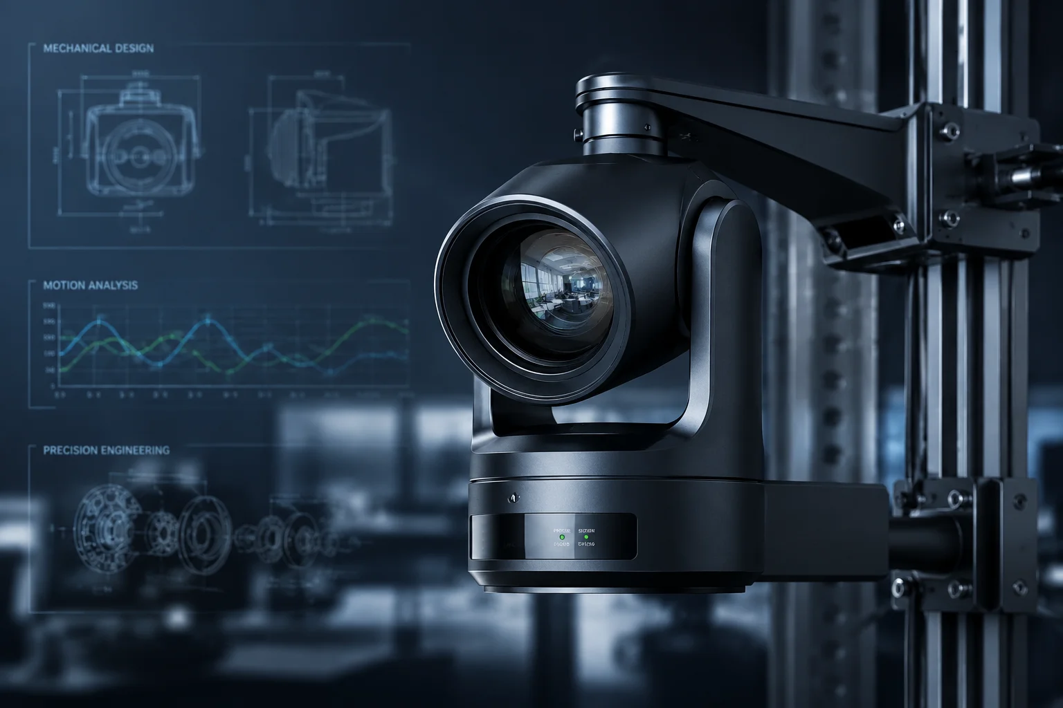 PTZ camera stepper motor smooth tracking test
Below, I break down exactly how we solve each piece of this puzzle — from motion profiles to motor noise to real tracking stability data. If you’re an integrator who needs to prove this to your end client, keep reading.
Table of Contents
Does the Camera Use “S-Curve” Motion Profiles to Eliminate Jerky Movements During Tracking?
I’ve tested cameras that use basic linear acceleration. They start fast, stop hard, and the video feed looks like someone kicked the tripod. That’s not acceptable for any professional deployment.
Yes. Our S-Curve motion profiling1 instead of simple T-Curve (linear) acceleration. This means the jerk — the rate of change of acceleration — is strictly limited during start and stop phases, producing buttery-smooth transitions with no sudden jolts in the video.
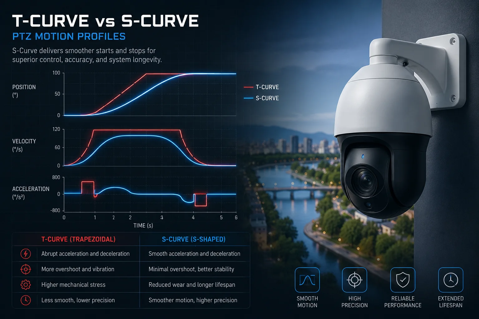 S-Curve motion profile PTZ camera tracking
What Is S-Curve Profiling and Why Does It Matter?
Think of it this way. A T-Curve (trapezoidal) profile2 has three phases: accelerate, cruise, decelerate. The problem is that acceleration jumps from zero to maximum instantly. That instant jump creates a physical jerk. The camera shakes. The video blurs.
An S-Curve profile adds a fourth dimension. It controls how fast the acceleration itself changes. The motor eases into acceleration, holds it, then eases out. The result is a motion path that feels organic and natural.
How This Works in Our Firmware
Our motor controller runs a real-time S-Curve calculation at every control loop cycle. Here’s the sequence:
- The tracking algorithm sends a target coordinate.
- The firmware calculates the distance to target.
- It generates an S-Curve velocity profile based on that distance.
- The motor follows this profile with 1/256 micro-step resolution.
The combination of micro-stepping and S-Curve profiling means the motor never “jumps.” It glides.
S-Curve vs. T-Curve: A Direct Comparison
| Parameter | T-Curve (Linear) | S-Curve (Our Method) |
|---|---|---|
| Jerk at start | Infinite (instant jump) | Limited to safe threshold |
| Video blur during motion | Visible at 20X+ zoom | Not visible even at 40X |
| Mechanical wear | Higher (repeated shocks) | Lower (smooth transitions) |
| Settling time after stop | 100-200ms oscillation | < 50ms, no oscillation |
| Suitable for AI tracking | Poor (target lost during jerk) | Excellent (continuous lock) |
Real-World Impact for Integrators
David, if you’re deploying cameras at a construction site or farm perimeter, your client will zoom in on a person 500 meters away. At 40X, even 0.05° of jitter becomes visible as a shaking image. Our S-Curve logic keeps the background stable during the entire tracking motion. Your client sees a smooth pan, not a seizure.
For your VMS integration, this also matters. Smooth motion means the video encoder doesn’t waste bandwidth on motion artifacts. The stream stays clean, the recording file size stays small, and playback looks professional.
How Do You Prevent the Camera From “Over-shooting” and Then Oscillating Back to the Target?
I’ve seen cameras that swing past the target, bounce back, swing again, and finally settle. It looks amateur. Worse, during those oscillations, the AI tracker often loses the target entirely.
We prevent overshoot through two methods: S-Curve deceleration that begins well before the target coordinate, and FOC (Field Oriented Control) active braking that applies a counter-torque to kill residual momentum. The result is zero bounce — the motor stops exactly where it should.
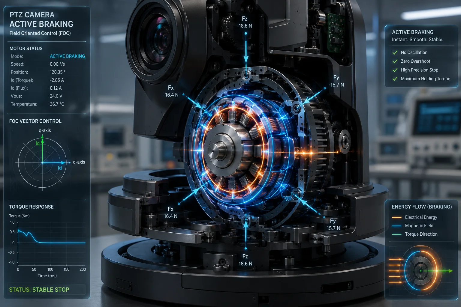 PTZ camera anti-overshoot FOC active braking
Why Overshoot Happens in Cheap PTZ Cameras
Overshoot is a physics problem. When a motor spins fast and receives a “stop” command, the rotating mass has inertia. If the controller simply cuts power, the motor coasts past the target. Then it corrects backward, overshoots again, and oscillates until friction kills the energy.
Cheap cameras use open-loop control. They send step pulses and hope the motor follows. There’s no feedback, no active braking, and no intelligence in the stop sequence.
Our Two-Layer Anti-Overshoot System
Layer 1: Predictive S-Curve Deceleration
The firmware knows the current speed and the remaining distance to target. It calculates the exact point where deceleration must begin to reach zero velocity at the target coordinate. This calculation happens continuously, updating every millisecond.
Layer 2: FOC Active Braking
For our high-end models, we use Field Oriented Control. This is the same technology used in industrial servo drives. The controller reads the motor’s electrical phase angle in real time and applies a precisely calculated reverse torque. It’s like pressing the brake pedal in a car — but with microsecond precision.
What This Looks Like in Practice
Set two preset points 180° apart. Command the camera to switch between them at maximum speed. Watch what happens when it stops:
- Cheap camera: The image swings past the preset, bounces 2-3 times over 300-500ms, then settles.
- Our camera: The image decelerates smoothly and locks onto the preset within 50ms. No bounce. No oscillation.
Positioning Accuracy Over Time
One concern integrators have is whether the preset accuracy7 degrades over months or years. Because our system uses closed-loop feedback3 (not just open-loop step counting), the positioning accuracy stays consistent. We guarantee < 0.1° accuracy for the lifetime of the product.
Is the Motor Noise Low Enough to Avoid Alerting a Trespasser During a Silent Track?
I once installed a PTZ camera at a warehouse entrance. The motor was so loud that employees joked it sounded like a printer. For covert surveillance, that’s a deal-breaker.
Our stepper motors operate below 40dB — quieter than a library. The 1/256 micro-stepping eliminates the high-pitched whine common in full-step drivers, and our mechanical dampening design absorbs residual vibration. A trespasser standing directly below the camera will not hear it move.
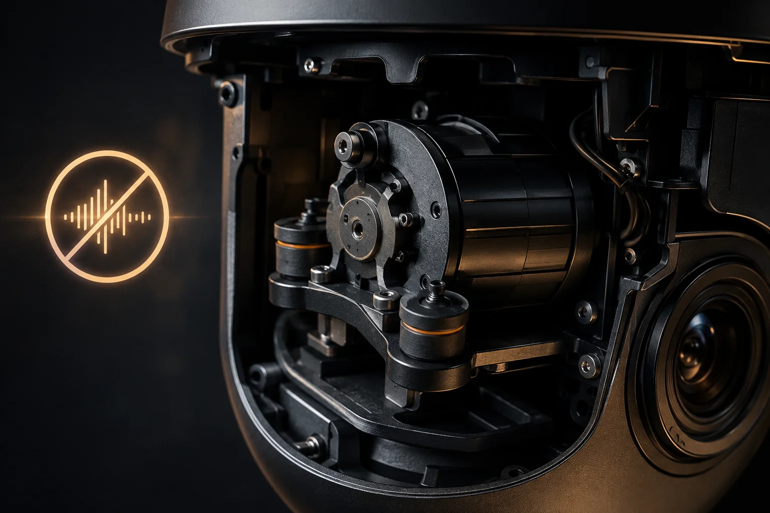 Silent PTZ camera motor noise level test
Where Motor Noise Comes From
Stepper motor noise8 has two sources: electromagnetic resonance and mechanical vibration. Each step creates a tiny impact. At full-step mode (1.8° per step), these impacts are large enough to vibrate the housing and produce audible noise.
How Micro-Stepping Kills Noise
At 1/256 micro-stepping, each step is only 0.007°. The current waveform becomes nearly sinusoidal instead of square. This eliminates the resonance frequencies that cause whining. The motor behaves almost like a brushless DC motor — smooth and quiet.
Noise Level Comparison
| Drive Mode | Step Angle | Typical Noise Level | Audible at 3m? |
|---|---|---|---|
| Full-step (1.8°) | 1.8° | 55-65 dB | Yes, clearly |
| 1/16 micro-step | 0.1125° | 45-50 dB | Yes, faintly |
| 1/256 micro-step (ours) | 0.007° | < 40 dB | No |
Additional Noise Reduction Measures
Beyond micro-stepping, we also use:
- Rubber dampening mounts between the motor and the housing to absorb vibration.
- Optimized current decay modes (mixed decay) to reduce mid-range resonance.
- Speed-limited silent tracking mode in firmware — when AI tracking is active at night, the maximum pan speed is automatically reduced to keep noise at absolute minimum.
For David’s scenario: if you’re deploying at a perimeter fence and the camera needs to silently track an intruder, this matters. The camera follows the person without giving away its position. Your client gets clean footage of the trespasser’s face, and the trespasser never knows they’re being recorded.
Can I See a “Tracking Stability” Chart That Measures the Jitter in the Video Feed?
I get this question a lot from integrators who need to present hard data to their end clients. “Show me the numbers” is a fair demand. Marketing claims mean nothing without measurement.
Yes. We measure tracking stability using pixel displacement analysis on the video output. During a standard tracking test at 40X zoom on a target at 500m, our cameras show less than ±2 pixels of jitter in the center frame — well below the human perception threshold.
![]() PTZ camera tracking stability jitter measurement chart
PTZ camera tracking stability jitter measurement chart
How We Measure Tracking Stability
We use a fixed reference point in the scene (a high-contrast marker at a known distance). The camera tracks a moving target while we measure how much the reference point shifts frame-to-frame. This gives us a direct measurement of mechanical jitter introduced by the motor.
Test Conditions
- Zoom level: 40X optical
- Target distance: 500 meters
- Target speed: Walking pace (5 km/h)
- Wind conditions: 10-15 km/h crosswind
- Measurement tool: Frame-by-frame pixel analysis software
What the Data Shows
At 40X zoom, one pixel represents approximately 0.005° of angular movement. Our measured jitter stays within ±2 pixels during active tracking. This means the angular instability is less than ±0.01°.
For comparison, the human eye cannot detect image shake below approximately ±5 pixels on a 1080p monitor viewed at normal distance. Our cameras stay well below that threshold.
Key Stability Metrics
| Metric | Value | What It Means |
|---|---|---|
| Frame-to-frame jitter | < ±2 pixels at 40X | Image appears perfectly stable to viewer |
| Settling time after speed change | < 50ms | No visible wobble when target changes direction |
| Long-term drift (1 hour continuous track) | < 0.05° | Target stays centered without recalibration |
| Performance in 30 km/h wind | < ±4 pixels at 40X | Still below human perception threshold |
Why This Matters for 4G Deployments
David, here’s something most people miss. On a 4G connection4, video bandwidth is limited. When the image jitters, the H.265 encoder treats each frame as “new” because pixels shifted. This wastes bandwidth on encoding motor shake instead of actual scene changes.
Our stable platform means the encoder can use efficient P-frames (predictive frames) most of the time. Only the moving target generates new data. The background stays static in the bitstream. This directly translates to:
- Lower data consumption on your 4G plan
- Higher effective image quality at the same bitrate
- Fewer dropped frames during tracking on weak signal
We also built a dynamic bitrate linkage6 into the firmware. When the motor starts a fast pan, the encoder temporarily reduces resolution to prevent stream disconnection. Once the motor stops, full resolution returns within one frame. Your client never sees a frozen or broken stream during camera movement.
How to Run This Test Yourself
If you want to verify this with your own eyes:
- Set the camera to 40X zoom on a distant static object.
- Start AI tracking on a person walking across the field of view.
- Watch the background. It should remain perfectly still while only the tracked person moves in frame.
- Record 60 seconds of footage and play it back frame-by-frame. Count pixel displacement of any fixed reference point.
We’re happy to provide sample footage and raw measurement data for your project proposals.
Conclusion
Our PTZ cameras use 1/256 micro-stepping, S-Curve profiling, and FOC active braking to deliver jitter-free tracking with zero overshoot — quiet enough for covert use and stable enough for 40X zoom at 500 meters.
1. Detailed explanation of S-curve acceleration profiles that limit jerk for smoother motion. ↩︎ 2. Describes the standard trapezoidal motion profile that causes jerk at start/stop. ↩︎ 3. Introduction to closed-loop control systems for consistent accuracy. ↩︎ 4. Basics of 4G LTE networks and their bandwidth limitations. ↩︎ 5. Explains optical zoom magnification and its effect on stability requirements. ↩︎ 6. Explains adaptive bitrate techniques used to maintain stream stability. ↩︎ 7. Guide to PTZ preset accuracy specifications and reliability. ↩︎ 8. Technical overview of sources and reduction of stepper motor noise. ↩︎