
I once lost a $12,000 contract because a dual-lens PTZ drifted out of alignment after three months in the Texas heat. That failure taught me everything about why factory calibration matters.
Factories achieve millisecond-level lens alignment through a four-stage process: 6-DOF robotic active alignment at the micron level during assembly, automated MTF scanning for sharpness validation, dynamic LUT compensation in firmware for real-time correction, and master clock triggering for nanosecond-level frame synchronization between sensors.
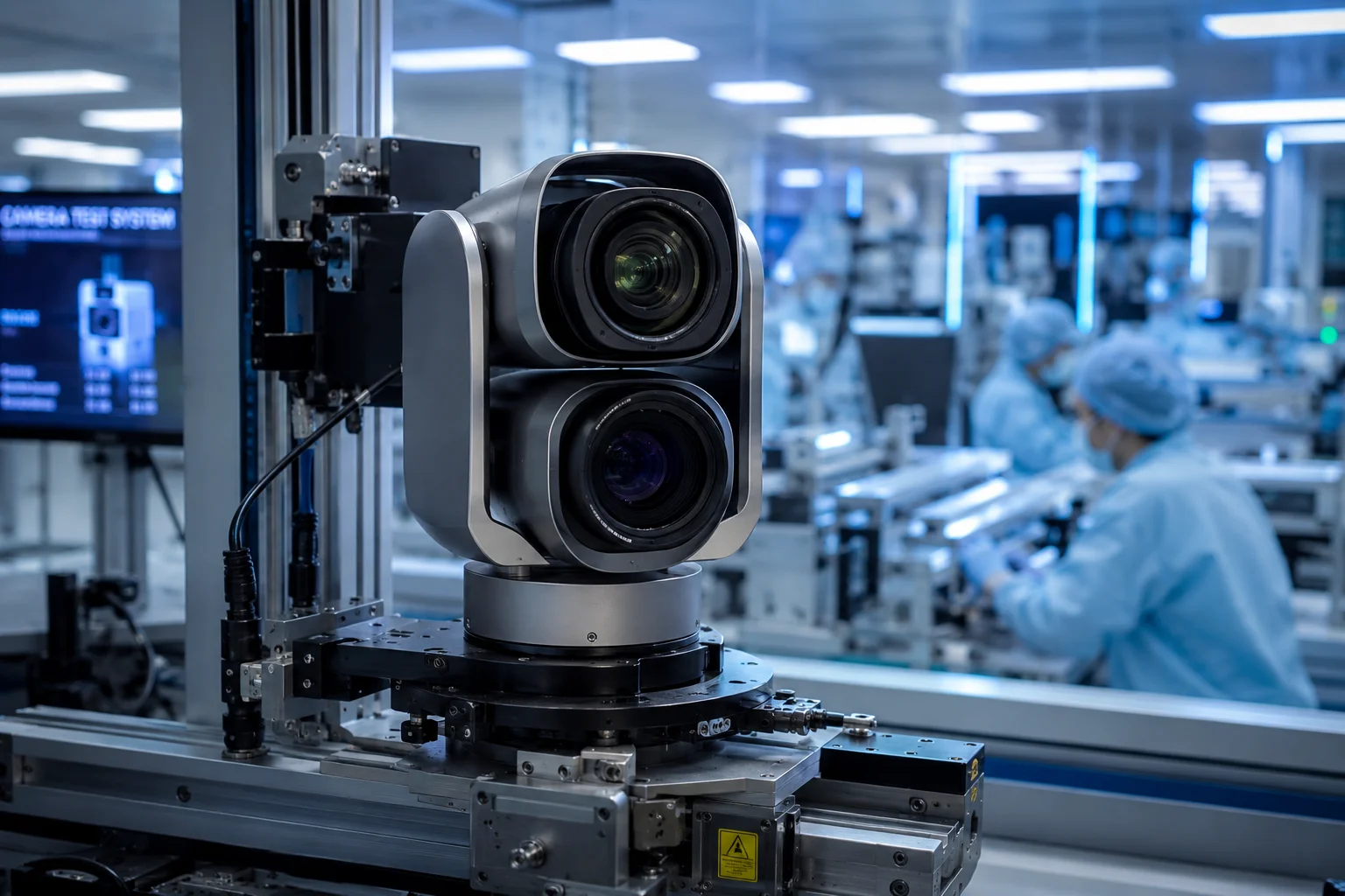 dual lens PTZ camera factory calibration alignment
Below, I break down each step of this calibration chain. I will explain the pixel-to-coordinate mapping, remote recalibration options, full-rotation precision, and thermal drift prevention. If you are sourcing dual-lens PTZ cameras for critical infrastructure, this is the engineering detail that separates a reliable unit from a warranty nightmare.
Table of Contents
What Is the “Pixel-to-Coordinate” Mapping Process Used to Sync the Two Lenses During Production?
When I first visited our calibration lab, I expected to see technicians with screwdrivers. Instead, I saw robots, UV lamps, and giant checkerboard targets. The old way of manual alignment is dead.
Pixel-to-coordinate mapping is a factory process where each lens captures a precision calibration target at every zoom level. Software then records the exact pixel offset between the two optical axes and stores this data as a lookup table (LUT) in the camera’s firmware for real-time correction.
 pixel to coordinate mapping calibration target dual lens
How the Physical Alignment Happens First
Before any software mapping begins, the lenses must be physically positioned with extreme precision. Our factory uses 6-DOF (six degrees of freedom) robotic arms. These robots adjust the lens module in six directions: X, Y, Z, Tilt, Tip, and Rotation. The precision is at the micrometer level.
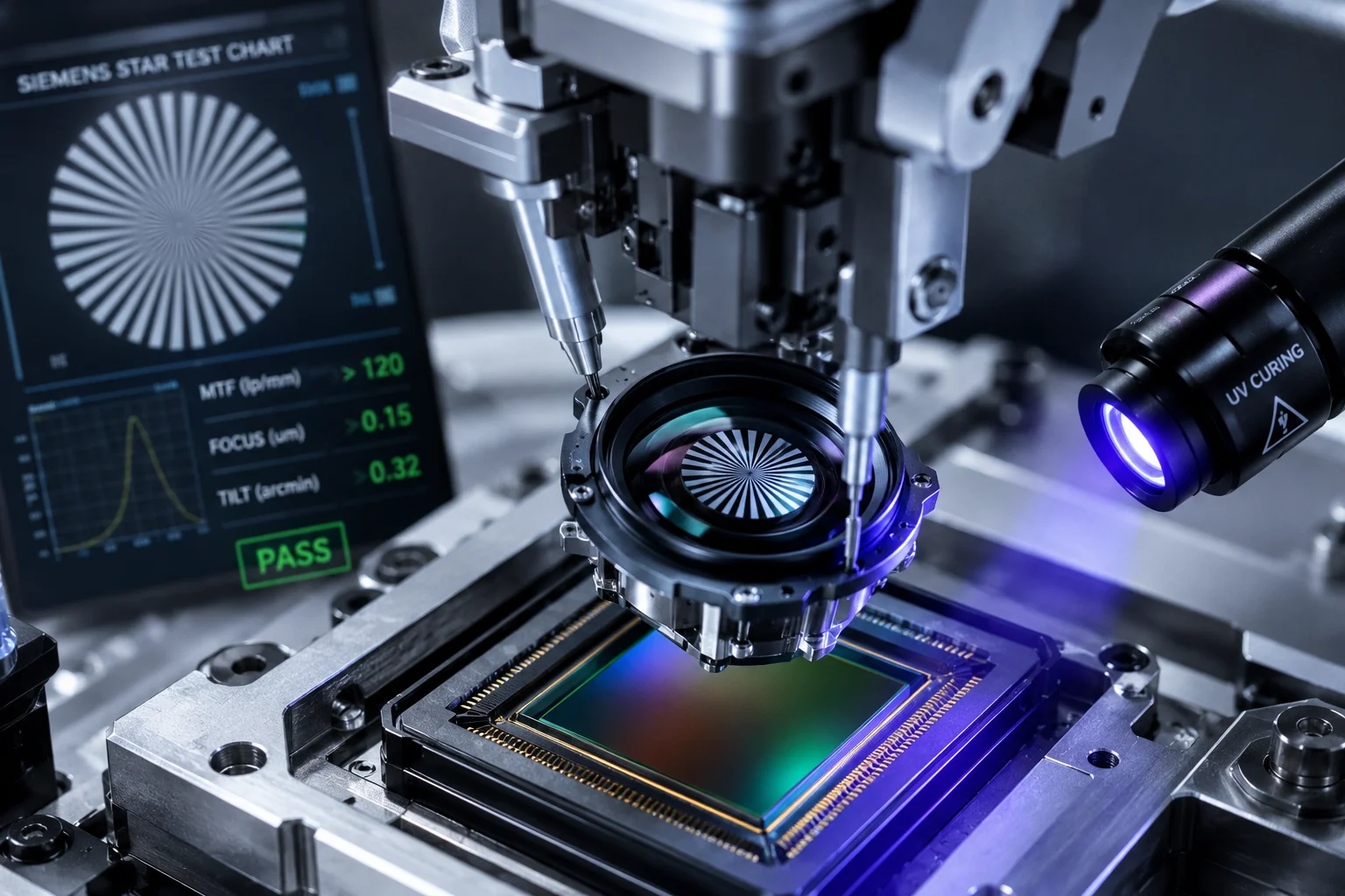
Here is how the sequence works. The camera module is powered on during assembly. A live image feeds into the alignment algorithm. The robot arm holds the lens above the sensor while optical adhesive sits between them, still liquid. The algorithm analyzes a Siemens Star test chart1 in real time. It checks the MTF (Modulation Transfer Function)5 value at the center and all four corners of the image. When all five zones hit peak sharpness at the same instant, a UV lamp fires. The adhesive cures in about 200 milliseconds. The lens is now locked in place.
The Software Mapping Stage
After physical alignment, the camera faces a large, high-precision checkerboard calibration target. The system then runs through every focal length the zoom lens supports. At each zoom step, it records the pixel coordinates where the same reference point appears in both the visible-light image and the thermal image (or the second visible lens).
The result is a table of offset values. For example, at 10X zoom, the thermal image center might be 3 pixels left and 2 pixels up compared to the visible image center. At 40X zoom8, that offset might change to 7 pixels right and 1 pixel down. Every zoom position gets its own correction value.
How the LUT Works in Real Time
This offset table is the LUT — the lookup table. It gets burned into the camera’s firmware before the unit leaves the factory. When you operate the PTZ and change the zoom level, the processor reads the current zoom position, looks up the corresponding offset, and commands the PTZ motor to micro-adjust. This happens in single-digit milliseconds. You never see it. The two images just stay aligned.
| Stage | What Happens | Output |
|---|---|---|
| Physical alignment | 6-DOF robot positions lens on sensor | Micron-level mechanical precision |
| Target capture | Camera images checkerboard at all zoom levels | Raw offset data per focal length |
| LUT generation | Algorithm computes (dx, dy) for each zoom step | Firmware lookup table |
| Runtime correction | Processor reads LUT and adjusts motor position | Millisecond-level live compensation |
Why This Matters for 40X Zoom
At 1X zoom, a small misalignment is invisible. But zoom magnifies errors. A 0.5-degree optical axis offset at 1X becomes a 20-degree apparent shift at 40X. The target walks right off your screen. This is why cheap PTZ cameras “lose the target” when you zoom in. They either skip the LUT process entirely or only calibrate at a few zoom positions instead of the full range.
Can I Perform a Remote “One-Click Calibration” if the Lenses Become Misaligned After a Storm?
I have had installers call me at 2 AM because a storm knocked their PTZ out of alignment. Sending a technician to a remote solar-powered site costs more than the camera itself. Remote recalibration is not a luxury — it is a survival feature.
Yes. Our PTZ firmware supports remote recalibration through the web interface or VMS integration. The system re-runs its internal LUT correction algorithm using a known reference point or built-in test pattern, restoring pixel-level alignment without a truck roll.
 remote one click calibration PTZ camera web interface
What Can Actually Shift After a Storm
Strong wind, hail impact, or thermal shock can cause micro-shifts in the PTZ housing. The lens elements themselves rarely move because the UV-cured adhesive is extremely strong. What moves is the relationship between the PTZ gimbal’s “home” position and the actual optical axis. Think of it this way: the lens is fine, but the platform it sits on has rotated 0.1 degrees. At 40X, that 0.1 degrees becomes a visible problem.
How Remote Recalibration Works
The process has three steps:
- Reference acquisition. The camera points to a known landmark or uses its built-in electronic crosshair pattern. The firmware captures frames from both lenses simultaneously.
- Offset recalculation. The onboard processor compares the current pixel offset against the factory LUT baseline. It calculates the new delta.
- Motor compensation update. The firmware writes a correction layer on top of the original LUT. The PTZ motors now include this additional offset in every movement command.
This entire process takes under 30 seconds. You trigger it from the camera’s web GUI or through an API call from your VMS.
Limitations You Should Know
Remote recalibration fixes software-correctable drift. It cannot fix physical damage. If a hailstone cracks the dome glass or bends the gimbal bracket, no software can compensate. The system will report a “calibration failure” if the measured offset exceeds the motor’s correction range. At that point, you need a site visit.
When to Use It vs. When to Call a Technician
| Symptom | Remote Fix Possible? | Action |
|---|---|---|
| Slight image offset after wind event | Yes | Run one-click recalibration |
| Offset grows slowly over months | Yes | Schedule periodic auto-recalibration |
| Sudden large offset after impact | Maybe | Try remote fix; if it fails, send technician |
| Visible physical damage to dome or bracket | No | Site visit required |
| Image blur or focus loss | No | Likely internal lens shift; RMA needed |
For David and other integrators working in remote areas — ranches, oil fields, solar farms — this remote recalibration feature directly reduces your total cost of ownership. One avoided truck roll pays for the camera’s price difference over a cheaper unit that lacks this capability.
Does the Calibration Hold Its Precision Across the Entire 360-Degree Rotation of the PTZ Module?
I tested a competitor’s unit once by panning it in a full circle at 40X zoom. By the time it returned to the starting position, the target had shifted 15 pixels. That is not calibration. That is a suggestion.
True calibration must hold across all 360 degrees of pan and all tilt angles. Our factory achieves this by mapping the LUT not just per zoom level, but per pan-tilt position, and by using precision harmonic drive gears that eliminate backlash in the rotation mechanism.
 PTZ 360 degree rotation calibration precision test
Why Rotation Introduces Error
A PTZ camera is not a fixed camera. Every time the gimbal rotates, mechanical tolerances stack up. Gear backlash, belt stretch, bearing play — all of these create tiny position errors. At 1X zoom, nobody notices. At 40X zoom, a 0.01-degree gear backlash translates to multiple pixels of drift.
There are two types of rotation error:
- Systematic error: Repeatable offsets that occur at the same position every time. These come from gear tooth spacing, mounting eccentricity, or cable drag.
- Random error: Non-repeatable jitter from bearing wear, vibration, or thermal expansion. These are harder to compensate.
How the Factory Handles Systematic Error
During production testing, the PTZ is commanded to rotate through its full range in fine steps. At each step, the system measures the actual pointing direction against the commanded direction. The difference is recorded. This creates a second lookup table — a pan-tilt correction map.
This map works alongside the zoom LUT. So when you command the camera to pan to 127.3 degrees and zoom to 35X, the firmware applies two corrections simultaneously: one for the zoom-dependent optical offset, and one for the position-dependent mechanical offset.
Harmonic Drive Gears: The Hardware Solution
Software correction has limits. If the mechanical error is too large or too random, no LUT can fix it. This is why gear selection matters enormously.
Our PTZ modules use harmonic drive gears3 (also called strain wave gears). These have near-zero backlash — typically under 1 arc-minute. Compare this to standard spur gears, which can have 10-20 arc-minutes of backlash.
The Full-Circle Test Protocol
Before any unit ships, it runs a full-circle repeatability test:
- Camera points at a reference target.
- Camera pans 360 degrees and returns to the same commanded position.
- System measures the pixel offset between the original frame and the return frame.
- Pass criteria: offset must be less than 2 pixels at maximum zoom.
If a unit fails this test, it goes back to the mechanical adjustment station. There is no software workaround for bad gears.
What This Means for Tracking Applications
If you use AI auto-tracking6 — where the camera follows a person or vehicle — calibration drift during rotation means the tracking box will slowly walk off the target. The AI will try to correct, creating a jerky, oscillating motion. With proper full-rotation calibration, the tracking stays smooth because the mechanical platform delivers exactly what the software commands.
How Do You Prevent Thermal Expansion From Affecting the Dual-Lens Coordinate Alignment Over Time?
I have seen cameras that work perfectly in the lab at 25°C and fall apart at 60°C on a rooftop in Arizona. Thermal drift is the silent killer of long-term calibration accuracy.
We prevent thermal drift through three methods: matched CTE (Coefficient of Thermal Expansion) materials in the lens housing, real-time temperature-compensated LUT adjustment in firmware, and a 72-hour thermal cycling stress test during production that validates stability from -40°C to +70°C.
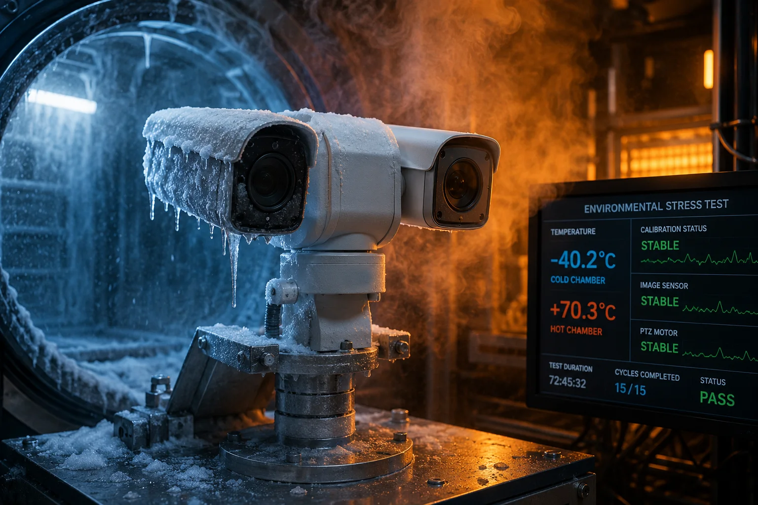 thermal expansion test chamber PTZ camera calibration
Why Heat Moves Your Lenses
Every material expands when heated. Aluminum expands about 23 micrometers per meter per degree Celsius. Steel expands about 12. Glass expands about 8. When your camera housing is aluminum, your lens barrel is steel, and your lens elements are glass, they all expand at different rates.
A 40°C temperature swing (morning to afternoon in a desert) can move lens elements by several micrometers relative to the sensor. At high zoom, several micrometers of physical shift equals several pixels of image shift. Your carefully calibrated alignment drifts.
Material Selection: The First Defense
The most effective solution is to prevent the problem at the source. Our optical assemblies use materials with matched thermal expansion coefficients wherever possible.
| Component | Material Choice | CTE (μm/m/°C) | Why This Material |
|---|---|---|---|
| Lens housing | Magnesium alloy | 26 | Light, strong, close to aluminum CTE |
| Sensor mount | Invar alloy4 | 1.2 | Near-zero expansion holds sensor position |
| Lens spacers | Ceramic | 6-8 | Matches glass CTE, keeps elements aligned |
| Main housing | Die-cast aluminum | 23 | Standard, cost-effective, predictable |
The critical interface is between the sensor and the last lens element. By using Invar (a nickel-iron alloy with almost zero thermal expansion) for the sensor mount, we keep the sensor-to-lens distance constant regardless of temperature.
Firmware-Level Thermal Compensation
Material matching reduces drift but cannot eliminate it completely. The remaining error is handled in firmware.
Each camera has an internal temperature sensor. The firmware reads this sensor continuously. Based on the current temperature, it applies a thermal correction offset to the base LUT. This offset was characterized during the factory thermal cycling test.
Here is the logic:
- At 25°C (reference temperature), the base LUT applies with zero thermal offset.
- At 50°C, the firmware adds a pre-measured correction — perhaps +1 pixel in X and -0.5 pixel in Y.
- At -20°C, it applies a different correction in the opposite direction.
This compensation runs continuously in the background. You never see it. The alignment just stays stable.
The 72-Hour Thermal Cycling Test
During production, every unit spends 72 hours in a thermal chamber. The chamber cycles between -40°C and +70°C repeatedly. At each temperature extreme and at several points in between, the automated test system captures calibration frames and measures alignment.
This test serves two purposes. First, it validates that the unit maintains alignment across its rated temperature range. Second, it generates the thermal compensation data that gets stored in firmware. Units that show excessive or unpredictable drift at any temperature point are rejected.
Long-Term Aging Effects
Even with all these measures, materials age. Adhesives can creep under sustained thermal stress. Plastics can warp. This is why our UV-cured optical adhesive2 is specifically chosen for its low creep rate and high glass transition temperature (Tg > 150°C). It will not soften or flow under any operating temperature the camera will encounter.
For David and other integrators deploying in extreme climates — whether it is a Texas oil field at 50°C or a Canadian border site at -35°C — this thermal engineering is what keeps your cameras accurate year after year without recalibration visits.
Conclusion
Factory-level millisecond calibration is a four-layer system: robotic physical alignment, full-range LUT mapping, temperature compensation, and hardware-triggered frame sync. When these layers work together, your dual-lens PTZ stays pixel-accurate from Day 1 through Year 5, across all zoom levels, all rotation angles, and all weather conditions.
1. Discover how the Siemens star test chart is used for optical resolution testing. ↩︎ 2. Understand the role of UV-cured adhesives in precision lens assembly. ↩︎ 3. Learn how harmonic drive gears provide near-zero backlash for PTZ rotation. ↩︎ 4. Explore how Invar’s low thermal expansion stabilizes sensor position. ↩︎ 5. Understand the standard measure of lens sharpness used in calibration. ↩︎ 6. Learn how AI-driven auto-tracking depends on precise calibration to maintain target lock. ↩︎ 7. Understand the fundamental process of mapping pixel positions to real-world coordinates. ↩︎ 8. Learn how optical zoom magnifies alignment errors and why full-range calibration is critical. ↩︎