
I’ve seen too many PTZ cameras that claim 255 presets but choke after the first 10. If you’re building large-scale surveillance systems, you need to know what actually happens when you hit “Go to Preset.”
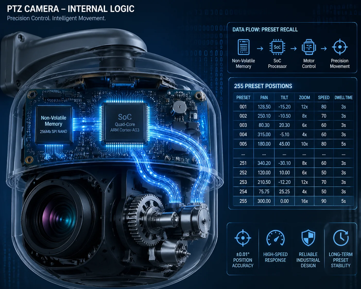
A well-engineered PTZ camera completes a 180-degree preset call in under 1.5 seconds. The backend stores absolute motor pulse counts, zoom position, and focus data for all 255 presets in non-volatile memory. The logic latency from command receipt to motor activation is under 50ms. The real speed bottleneck is always the physical pan and tilt motor, not the preset lookup.
 PTZ camera preset response speed and backend logic
Below, I break down the four questions I hear most from system integrators like David Miller — people who run hundreds of cameras across job sites and cannot afford a single preset to drift or lag. Let’s get into the details.
How Many Milliseconds Does It Take to Call a Preset Located 180 Degrees Away?
Every integrator I work with asks this question first. A slow preset call means missed events, wasted recording time, and angry end-clients. Speed is not optional — it’s the baseline.
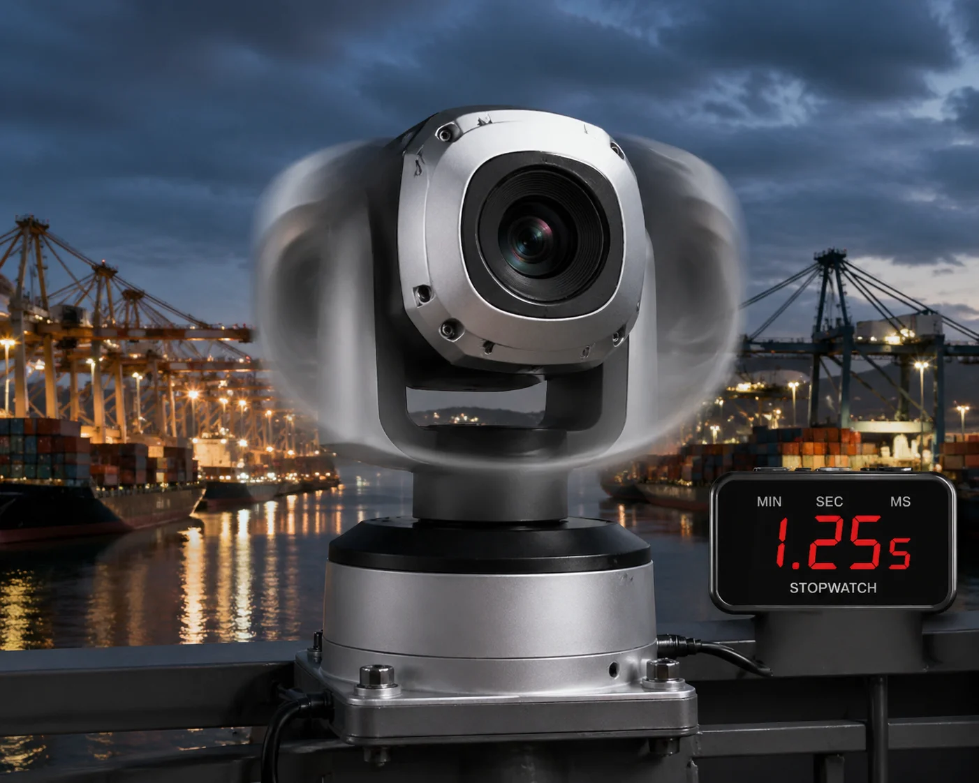
Calling a preset 180 degrees away takes under 1.5 seconds total. The logic latency — from command receipt to motor start — is under 50ms. The rest of the time is physical rotation. Our pan motors reach 240°/s to 300°/s, and tilt motors reach 160°/s to 200°/s. The camera accelerates, rotates, decelerates, and locks on target within that 1.5-second window.
 PTZ camera preset call speed 180 degrees rotation time
Breaking Down the Two Parts of “Response Speed”
When people say “response speed,” they usually mix up two very different things. Let me separate them clearly.
Part 1: Logic Latency. This is the time between the camera receiving your Call Preset command and the motor actually starting to move. On our industrial PTZ cameras, the main SoC 1 reads the preset coordinates from flash memory and converts them into motor pulse signals. This takes less than 50 milliseconds. Whether you call Preset 1 or Preset 255, the lookup time is the same. The preset number does not slow things down. The data structure is a flat table — every entry is accessed in constant time.
Part 2: Physical Rotation. This is where the real time goes. The camera has to physically spin the pan and tilt motors from point A to point B. Here’s what determines how long that takes:
| Factor | Typical Value | Impact on Speed |
|---|---|---|
| Pan motor max speed | 240°/s – 300°/s | Larger angle = more time |
| Tilt motor max speed | 160°/s – 200°/s | Vertical moves are slower |
| Zoom repositioning | Depends on focal length gap | Long zoom throws add 0.3–0.5s |
| Focus re-acquisition | Simultaneous with rotation | No extra delay if predictive focus is used |
| Acceleration/deceleration curve | Soft ramp built into firmware | Adds ~0.2s to each move |
Why “Under 1.5 Seconds” Matters in Real Deployments
Let me put this in context. If you run a guard tour with 16 presets and each preset call wastes 4 seconds (like many cheap PTZ cameras do), you lose over a minute per cycle just on transitions. That’s a minute of blind spots. With our cameras, the same 16-preset tour loses less than 24 seconds on transitions. That difference adds up across 24/7 operation.
The Hidden Factor: Simultaneous Zoom and Focus
Many low-end PTZ cameras move the pan/tilt motors first, then adjust zoom, then hunt for focus. That adds 2–3 seconds of blurry footage after every preset call. Our backend logic stores the focus motor position alongside every preset. When the camera starts rotating, the zoom and focus motors move at the same time. The result: when rotation stops, the image is already sharp. No “focus hunting.” No blurry seconds. This is what we call Snap Focus, and it is a direct result of how the backend stores and recalls preset data.
What About Network Delay?
If you use ONVIF over IP, the network adds 1–50ms of latency on a local LAN. Over a 4G connection, expect 30–150ms. Over RS-485 with Pelco-D protocol 2, the command itself transmits in microseconds. In all cases, the network delay is tiny compared to the physical rotation time. It is not the bottleneck.
Can I Prioritize Specific Presets in a “Guard Tour” with Different Dwell Times?
This is a question I get from every serious integrator. A guard tour that treats every preset equally is almost useless. You need to stare at the main gate for 30 seconds but only glance at the parking lot for 5 seconds.
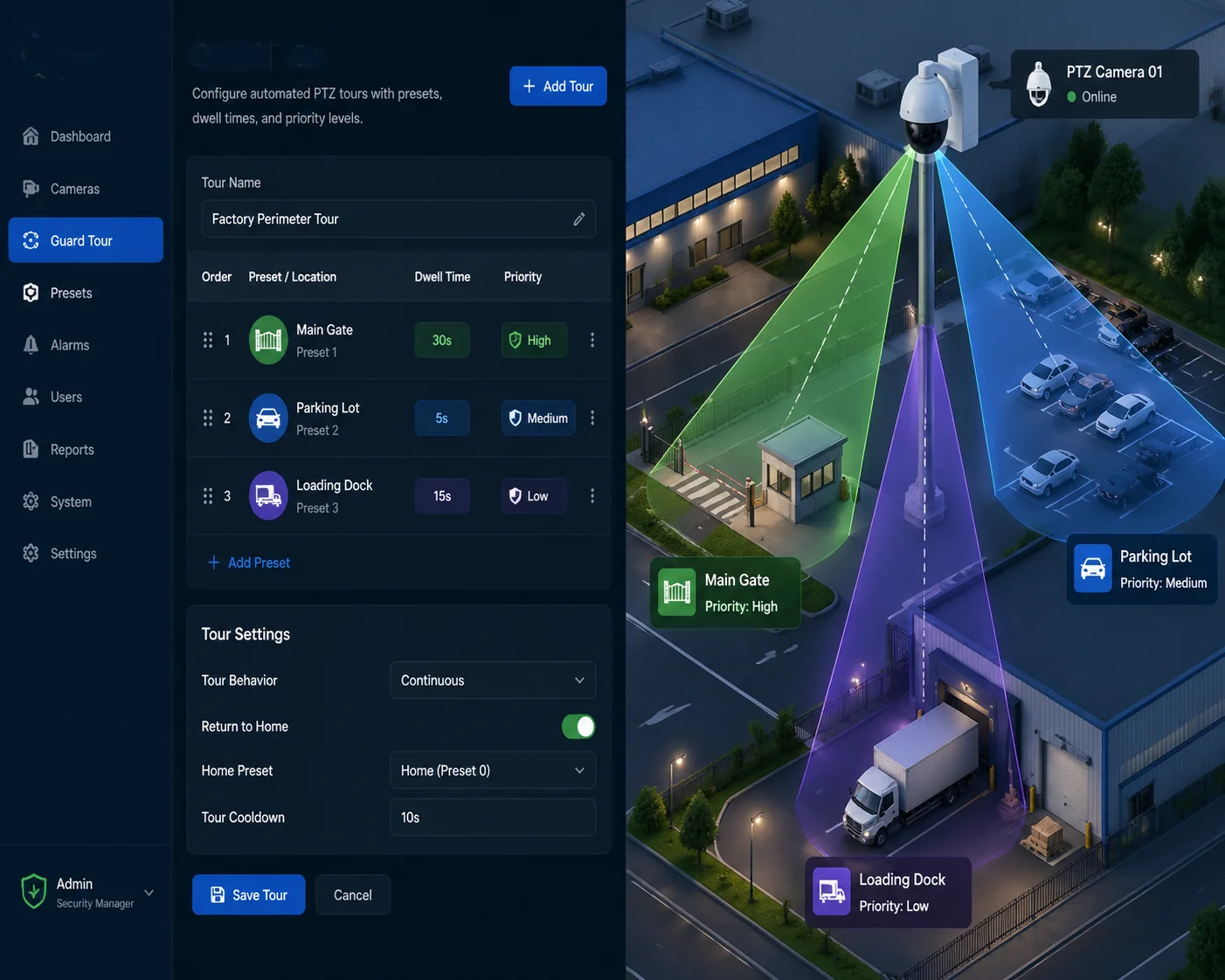
Yes. Our PTZ cameras support up to 8 independent cruise tours (guard tours), each containing up to 32 presets. Each preset within a tour can have its own dwell time, its own movement speed, and its own sequence priority. You configure this through the web interface, NVR, or ONVIF commands.
 PTZ guard tour preset dwell time configuration
How Guard Tours Actually Work in the Backend
A guard tour is a simple loop stored in the camera’s firmware. Each entry in the loop contains three pieces of information:
- Preset number (which position to go to)
- Dwell time (how long to stay there, in seconds)
- Movement speed (how fast to travel to that preset — slow, medium, or fast)
Here is an example of a real guard tour configuration:
| Tour Step | Preset Number | Dwell Time | Movement Speed |
|---|---|---|---|
| 1 | Preset 1 (Main Gate) | 30 seconds | High |
| 2 | Preset 5 (Parking Lot) | 5 seconds | Medium |
| 3 | Preset 12 (Loading Dock) | 20 seconds | High |
| 4 | Preset 3 (Perimeter Fence) | 10 seconds | Low |
| 5 | Preset 8 (Emergency Exit) | 15 seconds | High |
Why Different Dwell Times Matter for ROI
David Miller’s clients pay for monitoring results, not camera specs. If the camera spends equal time on a blank wall and the main entrance, the system is wasting half its value. By setting longer dwell times on high-priority presets, you get more recording time on the areas that matter. This directly reduces the number of cameras needed for a project. Fewer cameras means lower hardware cost, lower installation cost, and lower maintenance cost.
The “Preset Priority” Concept
Some integrators ask: “Can I interrupt a guard tour if an alarm triggers?” Yes. Most professional PTZ cameras support alarm-linked preset calls. When an external alarm (like a motion sensor or an AI detection event) fires, the camera immediately breaks out of the guard tour, jumps to the alarm-linked preset, stays there for a configurable time, and then resumes the tour. This is handled at the firmware level. The NVR or VMS sends an alarm-linked preset command, and the camera prioritizes it over the current tour step.
A Common Trap with Chinese PTZ Cameras
Some budget Chinese PTZ cameras “steal” preset numbers for special functions. For example, Preset 65 might trigger a tour start instead of going to a position. Preset 95 might reset the camera to factory defaults. I have seen integrators accidentally wipe their configurations by calling the wrong preset number from their VMS. Always ask the manufacturer for a preset number function mapping table before you integrate. At Loyalty-Secu, we provide this table with every product shipment. Our standard presets run from 1–255 with no hidden functions unless explicitly documented.
Does the Backend Logic Allow for “Soft-Start” and “Soft-Stop” to Reduce Mechanical Wear?
I’ve replaced PTZ cameras that died after 8 months because the motors were hammered by instant starts and hard stops on every preset call. Mechanical wear is a real cost — especially on remote sites where a truck roll costs more than the camera.
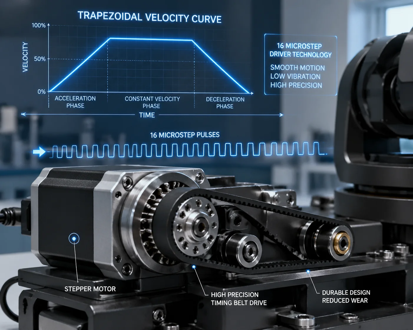
Yes. Our PTZ cameras use firmware-controlled acceleration and deceleration curves (soft-start and soft-stop) on every preset call. The stepper motors ramp up gradually and ramp down before reaching the target position. This reduces gear wear, belt stress, and vibration. Combined with microstep driver technology, the motors operate smoothly even at maximum speed.
 PTZ camera soft start soft stop motor wear reduction
What “Soft-Start” and “Soft-Stop” Actually Mean at the Motor Level
A PTZ camera’s pan and tilt movements are driven by stepper motors (or in some cases, DC servo motors with encoders). When you call a preset, the motor needs to go from zero speed to full speed, travel the required distance, and then stop exactly at the target coordinate.
Without soft-start/soft-stop, the motor receives full voltage instantly. It jerks into motion, vibrates, and slams to a halt at the target. This creates three problems:
- Gear tooth stress. Hard starts put peak load on the gear teeth. Over thousands of cycles, teeth wear down or crack.
- Belt slippage. If the camera uses a timing belt (common in dome PTZ designs), sudden torque can cause micro-slippage. Over time, this leads to preset drift.
- Image vibration. A hard stop causes the camera housing to oscillate for 0.5–1 second. The image shakes. Recording quality drops.
How Our Firmware Handles It
Our motor control firmware uses a trapezoidal velocity profile:
- Ramp-up phase: The motor accelerates from zero to target speed over approximately 0.1–0.2 seconds.
- Cruise phase: The motor runs at full speed for the majority of the travel distance.
- Ramp-down phase: The firmware calculates the deceleration point based on remaining distance. The motor slows down gradually and stops precisely at the target pulse count.
This is not a simple on/off switch. The firmware continuously calculates the optimal deceleration point based on current speed and remaining distance. If the preset is very close (say, 5 degrees away), the motor may never reach full speed — it just does a gentle, short move.
Microstep Drivers: The Precision Layer
Our stepper motors use microstep drivers. This means each full step of the motor is divided into smaller steps. The result:
- Smoother motion. The motor moves in tiny increments instead of large jumps. Less vibration, less noise.
- Higher precision. A full 360-degree pan rotation is divided into tens of thousands of micro-positions. Preset accuracy reaches ±0.1 degrees.
- Lower resonance. Full-step driving at certain speeds causes resonance (the motor vibrates and loses torque). Microstepping eliminates this problem.
The Auto-Calibration Safety Net
Even with soft-start/soft-stop, long-term 24/7 operation can cause tiny cumulative errors. A belt stretches slightly. A gear wears down by a fraction of a degree. After 3 months, Preset 1 is no longer centered on the main gate. David Miller’s worst nightmare.
Our solution: automatic zero-point calibration. On every power-up (and optionally every 24 hours), the camera rotates to find its mechanical zero point using an optical coupler switch. This resets the absolute position reference. All 255 presets are then measured from this confirmed zero point. Drift is eliminated before it becomes visible.
Will Calling a Preset Trigger an Immediate AI Re-Scan of the New Scene?
This is the question that separates a modern PTZ camera from a legacy one. If your camera moves to a new preset and the AI engine takes 5 seconds to “wake up” and start detecting, you’ve already missed the intruder.
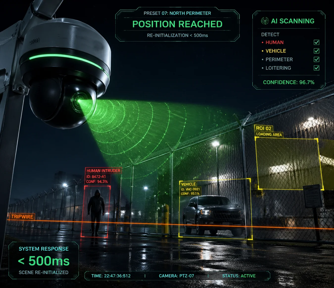
Yes. On our AI-equipped PTZ models, calling a preset triggers an immediate scene re-initialization. The AI engine begins processing the new field of view within 300–500ms of the camera reaching its target position. Human and vehicle detection is active before the first full dwell-time second has passed. There is no manual re-arm required.
 PTZ camera AI re-scan after preset call scene detection
How the AI Pipeline Responds to a Preset Change
When a PTZ camera moves to a new preset, the entire visual scene changes. The AI detection engine needs to handle this transition without generating false alarms and without missing real targets. Here is how our system manages it:
Step 1: Scene Change Detection
The moment the camera starts moving, the AI engine recognizes that the video frames are in motion. It temporarily suppresses detection to avoid false alarms caused by motion blur and scene transition. This suppression lasts only during the physical rotation — typically under 1.5 seconds.
Step 2: Scene Stabilization Check
Once the camera reaches the target preset and the motors stop, the firmware sends an internal “position reached” signal to the AI processing module. The AI engine waits for 1–2 stable frames (approximately 30–60ms at 30fps) to confirm the image is no longer moving.
Step 3: Immediate Re-Scan
The AI engine runs its detection model on the first stable frame. On our cameras with dedicated NPU (Neural Processing Unit) 3 hardware, a single frame analysis takes approximately 30–50ms. Human detection, vehicle detection, and intrusion zone checks all run in parallel.
| AI Pipeline Stage | Time Required | Notes |
|---|---|---|
| Motor rotation (180°) | ~1.2–1.5 seconds | Soft-start/soft-stop included |
| Frame stabilization | ~30–60ms | Waiting for 1–2 clean frames |
| First AI inference | ~30–50ms | NPU-accelerated detection |
| Total time to first detection | ~1.3–1.6 seconds | From preset call to active AI |
Why This Matters for Guard Tour + AI Combinations
If you run a guard tour with 16 presets and 10-second dwell times, the camera visits each preset for 10 seconds. If the AI takes 5 seconds to start detecting at each stop, you only get 5 seconds of actual AI coverage per preset. That’s a 50% efficiency loss.
With our system, the AI is active within the first second. You get approximately 9 out of 10 seconds of full AI coverage at each preset. Over a 24-hour period, this difference adds up to hours of additional effective monitoring.
The Role of Preset-Linked AI Zones
Our cameras also support preset-linked detection zones. This means you can draw different intrusion detection areas, tripwire lines, and region-of-interest boxes for each preset. When the camera arrives at Preset 5, it automatically loads the detection zones you configured for Preset 5. When it moves to Preset 12, it loads the zones for Preset 12. This is all stored in the camera’s local memory. The NVR does not need to push zone configurations on every preset change.
This feature is critical for integrators who deploy PTZ cameras in complex environments. A single camera might monitor a gate (Preset 1, with a tripwire across the entrance), a parking lot (Preset 5, with a region-of-interest around the vehicle lane), and a rooftop (Preset 12, with an intrusion zone along the edge). Each scene has completely different detection needs. Preset-linked AI zones handle this automatically.
Conclusion
The 255 presets are not just a number on a spec sheet. They are backed by precision motor control, predictive focus, auto-calibration, and AI-ready firmware. For integrators who need speed, accuracy, and zero drift over years of 24/7 operation, the backend logic behind each preset call is what separates a reliable deployment from a costly failure.
1. System-on-Chip (SoC) architecture for PTZ preset lookup. ↩︎ 2. Pelco-D RS-485 protocol for PTZ camera control. ↩︎ 3. Neural Processing Unit (NPU) for edge AI inference. ↩︎ 4. Non-volatile memory preset storage for 255 positions. ↩︎ 5. Accelerated life testing for PTZ motor gear wear. ↩︎ 6. Stepper motor microstepping for smooth PTZ motion. ↩︎ 7. Trapezoidal velocity profile vs square wave motor control. ↩︎ 8. Optical coupler zero-point calibration for preset drift. ↩︎ 9. ONVIF preset management and metadata standards. ↩︎ 10. Region-of-interest (ROI) configuration per VMS preset. ↩︎