
I’ve watched a perfectly stable 4G solar PTZ camera reboot mid-stream because someone hit the 40X zoom button too fast. That single moment of voltage sag cost my client a truck roll to a remote site.
The system suppresses voltage dips through a combination of bulk capacitors5 for instant energy buffering, S-curve motor soft-start algorithms that spread current draw over time, and dedicated Buck-Boost regulators that isolate sensitive modules like the 4G modem and SoC from transient voltage drops caused by PTZ motor peaks.
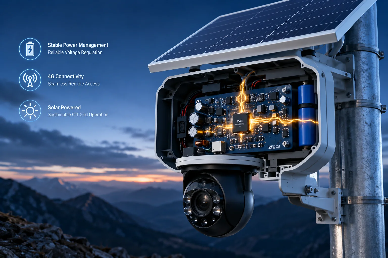 PTZ camera voltage dip suppression during zoom motor movement
Below, I break down each layer of this protection system. I’ll explain how the PMIC keeps your modem alive, why simultaneous pan-tilt-zoom won’t kill your stream, how we prevent false shutdowns, and why PCB power rail isolation matters for 4K image quality.
Table of Contents
Does the Power Management IC (PMIC) Stabilize the Voltage for the 4G Modem During PTZ Peaks?
I’ve seen 4G modems drop their LTE connection because the zoom motor stole just enough voltage for just long enough. It happens in milliseconds, and the modem treats it like a power failure.
Yes. The PMIC uses a high-efficiency Buck-Boost converter1 to maintain a stable 3.3V rail for the 4G modem, even when the main battery voltage sags during PTZ motor startup. This dedicated regulation stage acts as a buffer between the noisy motor load and the sensitive cellular module.
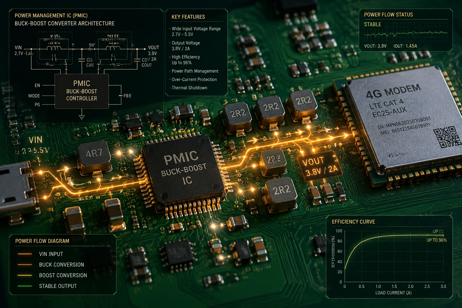 PMIC stabilizing voltage for 4G modem during PTZ motor peak current
How the PMIC Actually Works in This Context
A Power Management IC (PMIC)2 is not just a single voltage regulator. In our PTZ camera design, it is a multi-output chip that takes the battery input (typically 12V) and creates several independent, regulated outputs. Each output serves a different subsystem.
The 4G modem needs clean, stable 3.3V power. The SoC needs 1.2V and 1.8V rails. The motor driver needs the full 12V. The PMIC handles all of these from one input source.
Why Buck-Boost Topology Matters
A simple Buck (step-down) converter fails when the input voltage drops below the output voltage. During a heavy zoom operation, the battery voltage can momentarily dip from 12V down to 10V or even lower. A Buck-Boost converter works in both directions. It can step voltage down when the battery is full, and step it up when the battery sags. This means the 3.3V output stays at 3.3V regardless of what the motor is doing to the main rail.
The Decoupling Strategy
Between the PMIC output and the 4G modem input, we place additional decoupling capacitors. These are small ceramic capacitors (typically 10µF to 100µF) placed physically close to the modem’s power pins. They act as a final filter, catching any high-frequency noise that passes through the PMIC.
| Component | Role | Why It Matters |
|---|---|---|
| Buck-Boost PMIC | Maintains stable output across wide input range | Prevents modem brownout during motor peaks |
| Ceramic Decoupling Caps | Filters high-frequency ripple at modem input | Stops EMI from motor PWM reaching modem |
| Ferrite Bead | Blocks conducted noise on power trace | Isolates motor switching noise from modem rail |
| UVLO Circuit | Shuts down gracefully below safe threshold | Prevents data corruption from unstable power |
Real-World Validation
In our testing, we simulate worst-case scenarios. We command a full-speed 40X zoom while the battery is at 30% charge and the 4G modem is mid-upload. We monitor the modem’s power rail with an oscilloscope. The acceptable ripple is less than 50mV peak-to-peak. If it exceeds that, the modem may drop packets or lose registration with the cell tower.
David, for your deployments in North America, this means your camera keeps streaming even when a security operator rapidly zooms in on a license plate. The modem never sees the voltage chaos happening on the motor side of the board.
Will My Video Stream Flicker or Reboot if I Move the Zoom and Tilt at the Same Time?
I had a client call me frustrated because every time his operator panned and zoomed simultaneously, the live feed froze for two seconds. He thought the camera was broken. It wasn’t. The power system was just poorly designed.
No. Our firmware uses a phase interleaving4 strategy that staggers motor startups by 20-50 milliseconds, preventing simultaneous peak current draw. Combined with bulk capacitor buffering, the video encoder and 4G modem maintain uninterrupted power even during aggressive multi-axis PTZ commands.
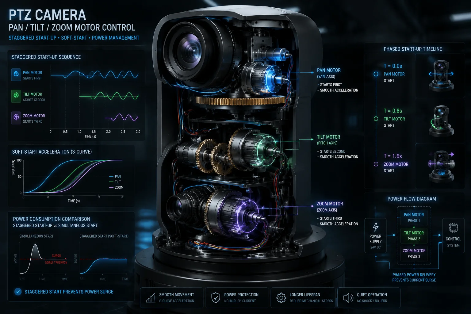 Video stream stability during simultaneous pan tilt zoom movement
Understanding the “Double Peak” Problem
Each PTZ axis has its own motor. The pan motor, the tilt motor, and the zoom motor can all receive commands at the same time. If all three start moving at the exact same instant, their startup currents stack. A single motor might draw 2A at startup. Three motors starting together draw 6A. On a solar battery system rated for 8A continuous, that 6A spike on top of the 2A baseline (SoC + modem + sensor) pushes the system to its limit.
How Phase Interleaving Solves This
The firmware never starts all motors at the same millisecond. When a “go to preset” command arrives that requires pan, tilt, and zoom movement, the system queues them:
- T = 0ms: Pan motor begins soft-start ramp
- T = 30ms: Tilt motor begins soft-start ramp
- T = 60ms: Zoom motor begins soft-start ramp
By the time the zoom motor starts drawing current, the pan motor has already passed its peak startup phase and settled into steady-state running current. The peaks never overlap.
The S-Curve Acceleration Profile
Even within each motor’s startup, the current doesn’t jump instantly. The firmware uses an S-curve acceleration profile3. Think of it like a car accelerating smoothly from a stop rather than flooring the gas pedal. The PWM duty cycle ramps up following a sigmoid function. This spreads the current draw over 50-100 milliseconds instead of hitting peak in under 5 milliseconds.
What Happens to the Video Pipeline
The video encoder (inside the SoC) has its own dedicated low dropout (LDO) regulator8. Even if the main 5V rail dips slightly, the LDO absorbs that variation and outputs a clean 1.8V to the encoder core. The 4K sensor also sits behind its own regulator. So the image pipeline is double-insulated from motor noise.
The result: no frame drops, no encoder resets, no stream interruptions. The operator sees smooth, continuous video while commanding complex PTZ movements.
Worst-Case Scenario Testing
We test this by scripting rapid preset tours. The camera cycles between 8 presets with zero dwell time, forcing constant multi-axis movement. We run this test for 72 hours straight on battery power. If the stream drops even once, the firmware team adjusts the interleaving timing or increases the soft-start ramp duration.
How Do You Prevent Battery “Voltage Sag” from Causing a False “Low Power” Shutdown?
I once debugged a system that kept shutting down at “40% battery.” The battery was fine. The BMS was reading the sagged voltage during motor movement and panicking. It thought the battery was dead when it was actually just under heavy load.
We prevent false shutdowns by sampling battery voltage only during motor idle periods, applying a moving-average filter to voltage readings, and setting the low-power threshold with a hysteresis band that accounts for expected sag under load. The system distinguishes between genuine low battery and temporary voltage dip.
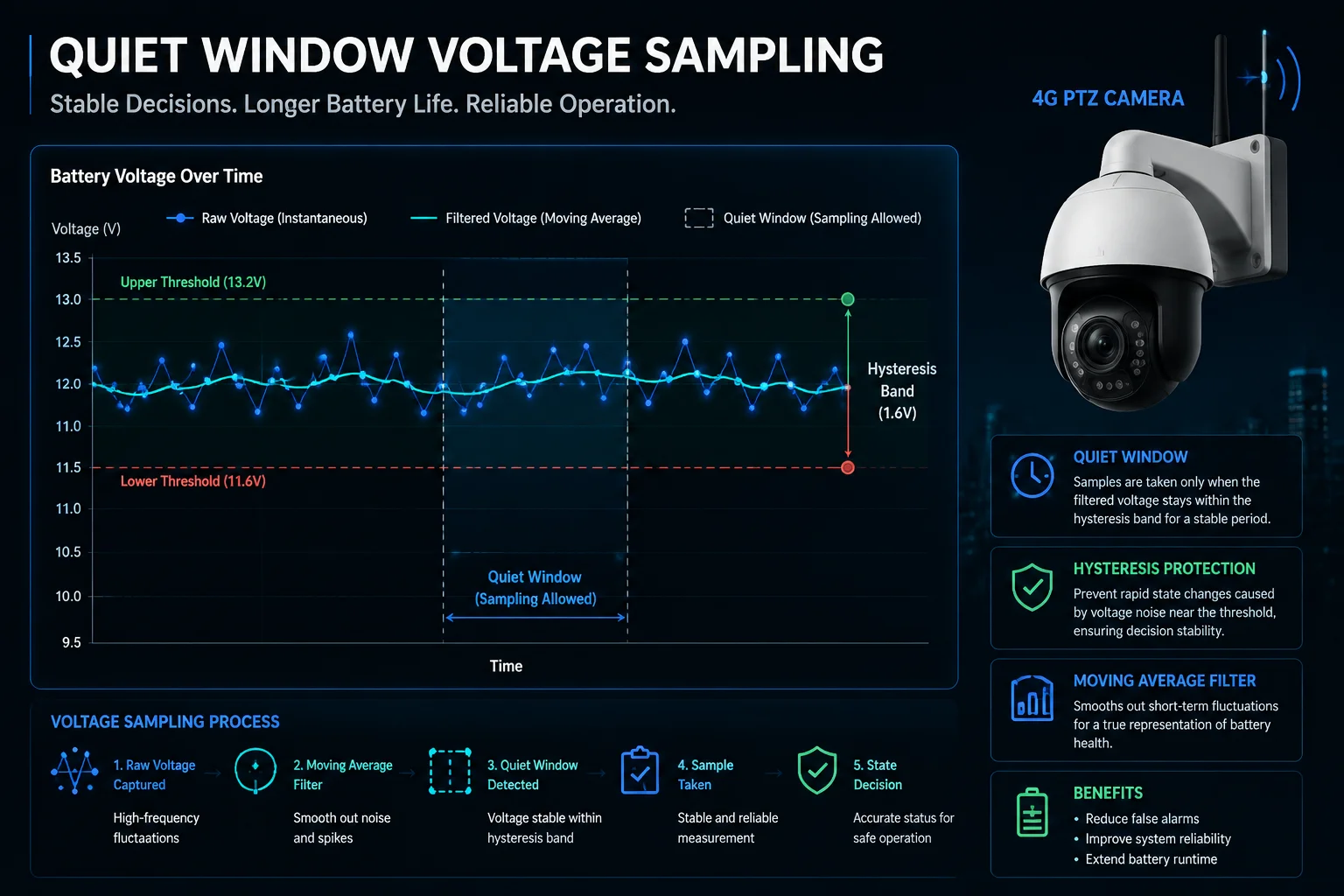 Battery voltage sag prevention false low power shutdown PTZ camera
The Root Cause of False Shutdowns
A lithium battery’s terminal voltage drops under load. This is normal physics. The battery has internal resistance. When current flows through that resistance, voltage drops (Ohm’s law: V = I × R). A battery showing 12.0V at rest might show 11.2V when delivering 5A to the motors. If the firmware reads voltage during that 5A draw and compares it to a static threshold (say, 11.0V = shutdown), it might trigger a false alarm.
Smart Voltage Sampling
Our firmware uses a technique I call “quiet window sampling.” The system knows when motors are active because it commands them. So it only takes battery voltage readings during periods when no motor is moving. If the camera is in continuous motion (like during a patrol tour), the firmware waits for the brief pause between preset transitions to grab a clean voltage sample.
The Hysteresis Band
| Battery State | Voltage Threshold | Action |
|---|---|---|
| Normal Operation | Above 11.5V (at rest) | All systems active |
| Low Power Warning | Below 11.5V for 30 seconds | Reduce non-essential tasks |
| Critical Low | Below 10.8V for 60 seconds | Graceful shutdown sequence |
| Recovery | Above 12.0V for 10 seconds | Resume normal operation |
Notice the gap between the shutdown threshold (10.8V) and the recovery threshold (12.0V). This is hysteresis. It prevents the system from rapidly cycling between shutdown and recovery.
Moving Average Filter
The firmware maintains a rolling average of the last 10 voltage samples, each taken 5 seconds apart during idle windows. A single low reading doesn’t trigger anything. The average must stay below threshold for a sustained period. This eliminates false triggers from brief transient events.
BMS Coordination
For David’s installations using external battery packs, we recommend a Battery Management System (BMS)9 with a discharge cutoff no higher than 10.0V (for a 12V system). This gives the camera’s internal logic room to manage graceful shutdown before the BMS hard-cuts power. If the BMS threshold is set too close to the camera’s own threshold, you get a race condition where both try to shut down at the same time, potentially corrupting stored footage.
The 10A Discharge Requirement
David, this is critical for your 40X cameras. The BMS must support at least 10A instantaneous discharge. Many off-the-shelf solar battery controllers are rated for 3-5A. That’s fine for a static camera. But a 40X PTZ with pan, tilt, zoom, and IR illuminator can briefly pull 8-9A. If your BMS can’t handle that, it will cut power and you’ll blame the camera. The camera is fine. The BMS is the bottleneck.
Are There Dedicated Power Rails on the PCB to Isolate the Noisy Motors from the 4K Sensor?
I learned this lesson early in my career. A single shared power trace between a stepper motor and an image sensor created horizontal banding in every frame. The noise was conducted straight through the power plane into the sensor’s analog circuits.
Yes. Our PCB uses physically separated power planes with dedicated copper pours for the motor driver section, the 4G modem section, and the imaging section. Each section has its own regulation stage, and the ground planes are connected at a single star-ground point to prevent ground loop interference.
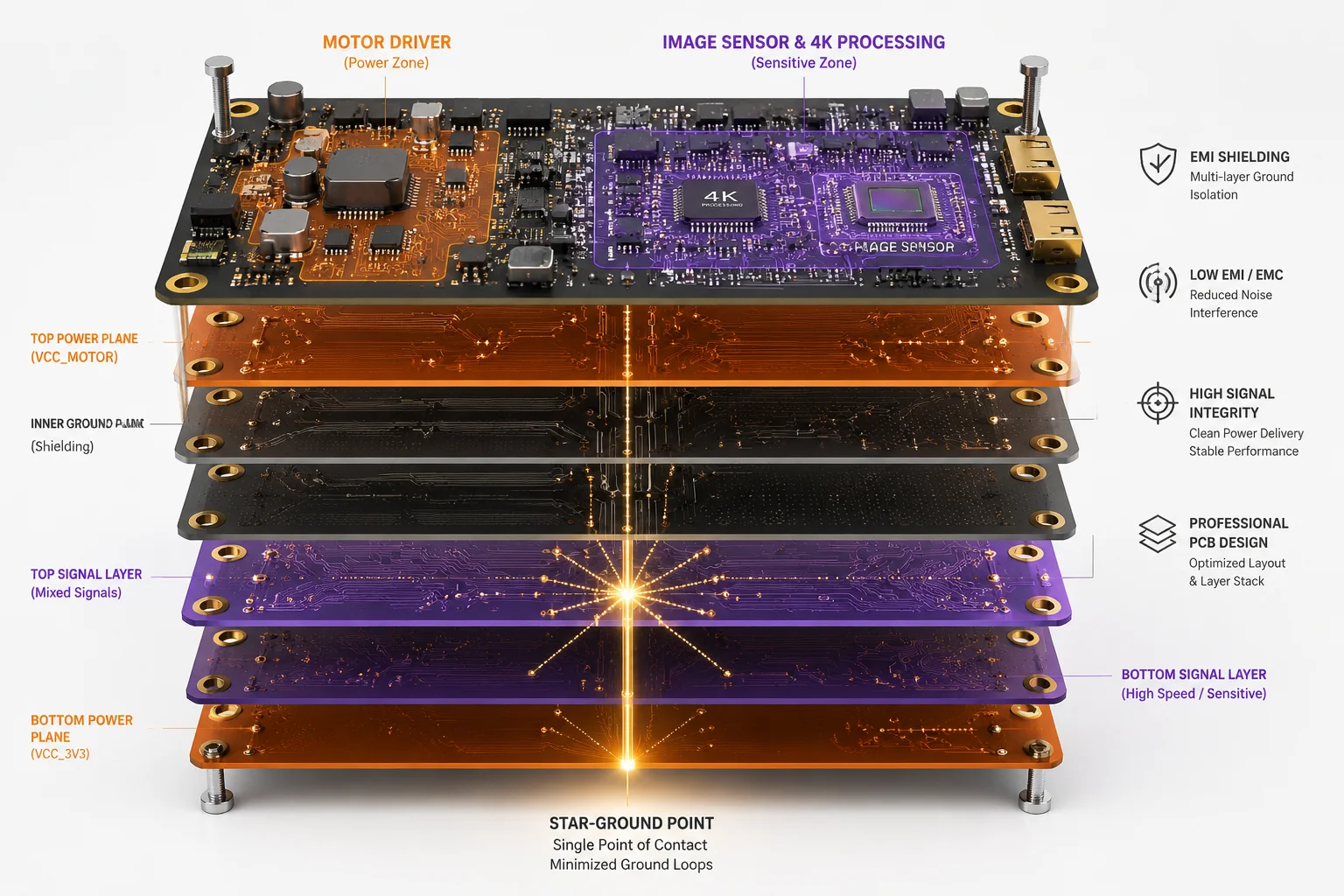 PCB dedicated power rails isolating motors from 4K sensor
Why Power Rail Isolation Is Non-Negotiable for 4K
A 4K image sensor operates with extremely small analog signals. The pixel voltages being read out are in the millivolt range. A motor driver switching at 20kHz generates electromagnetic interference (EMI) that can easily couple into those tiny signals. The result is visible noise in the image: banding, flickering exposure, or color artifacts.
The Three-Zone PCB Architecture
Our PCB is divided into three distinct power zones:
Zone 1: Motor Power This zone carries the high-current, noisy signals. The motor driver IC, the motor connectors, and the bulk capacitors all live here. The copper traces are wide (to handle 3-5A) and short (to minimize inductance). This zone has its own ground pour that connects to the main ground at one specific point.
Zone 2: Digital/Communication The 4G modem, SoC, memory, and storage live here. This zone receives clean, regulated power from the PMIC. It has its own ground pour. The 4G antenna feed line is routed as far from Zone 1 as physically possible.
Zone 3: Analog/Imaging The 4K sensor, its clock generator, and the analog front-end sit here. This is the most sensitive zone. It receives the cleanest power, often through a dedicated ultra-low-noise LDO regulator. The ground pour here is solid and unbroken, with no high-speed digital traces crossing it.
Star Ground Topology
The star ground topology6 approach means all three zones connect their ground planes at one single point near the battery input connector. Motor return current flows back through its own dedicated path and never passes under the sensor or modem.
Physical Separation on the Board
Beyond electrical isolation, we maintain physical distance. The motor driver IC sits on the opposite end of the PCB from the image sensor. The 4G modem antenna connector is on a different edge of the board from the motor connectors. This reduces both conducted and radiated coupling.
EMI Shielding
In some of our higher-end models, we add metal EMI shielding7 (small tin cans soldered over sensitive sections). The 4G modem module often has its own shield. The image sensor’s clock circuit may have a shield. These block radiated emissions from the motor driver from reaching sensitive components through the air.
David, for your 40X cameras capturing license plates at 200 meters, image quality is everything. A noisy power rail would degrade your effective resolution. Our rail isolation ensures that the 4K sensor delivers clean, sharp frames regardless of what the motors are doing.
Conclusion
Voltage dip suppression in PTZ solar cameras requires layered defense: bulk capacitors for instant energy, S-curve soft-start for current control, smart PMIC regulation for module isolation, and phase interleaving to prevent peak overlap. Each layer protects the next.
1. A Buck-Boost converter can step voltage up or down, maintaining stable output despite input voltage sag. ↩︎ 2. PMIC integrates multiple voltage regulators and management functions for different subsystems. ↩︎ 3. S-curve acceleration ramps motor speed smoothly over time, reducing current spikes. ↩︎ 4. Staggering motor startup times prevents overlapping peak currents from multiple motors. ↩︎ 5. Bulk capacitors store energy to instantly supply current during motor startup, reducing voltage sag. ↩︎ 6. Star ground connects multiple ground planes at a single point to avoid ground loops. ↩︎ 7. EMI shields block radiated interference from motor drivers to protect sensitive components. ↩︎ 8. LDO provides clean, stable voltage with minimal dropout, isolating sensitive sensors from rail noise. ↩︎ 9. BMS monitors and protects battery; its discharge cutoff must be compatible with camera’s thresholds. ↩︎