
I have seen too many integration projects fail at the last mile — not because of video, but because the alarm I/O refused to talk to the VMS. That one broken link can kill an entire deployment.
Yes, our PTZ cameras fully support remote I/O alarm triggering via ONVIF. The camera exposes its physical Alarm In and Alarm Out interfaces through the ONVIF protocol, allowing any compliant VMS or NVR software to both receive alarm notifications and send relay output commands over the network in real time.
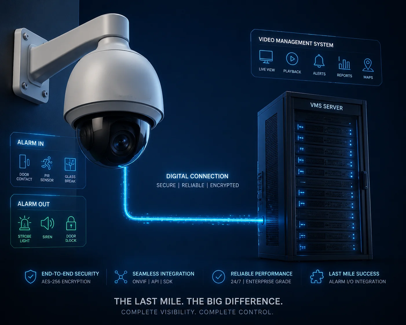 ONVIF remote I/O alarm triggering PTZ camera
But “support” is just the starting point. The real question is: how reliably does it work in your specific setup — especially over 4G, with a third-party VMS, in a remote location where nobody can drive out to fix things? Below, I break down the four most common questions I get from system integrators about ONVIF I/O triggering, and I give you the honest, technical answers.
Table of Contents
Can My NVR Software Trigger the Camera’s Built-in Siren Through the ONVIF Link?
Every month, I get emails from integrators who assumed their NVR could trigger the siren — only to find out during commissioning that the button is grayed out. That surprise costs real money.
Yes, most professional NVR and VMS platforms can trigger the camera’s built-in siren or searchlight through ONVIF by sending a SetRelayOutputState command. However, this only works if the camera supports ONVIF Profile T and the VMS has its event subscription feature manually enabled.
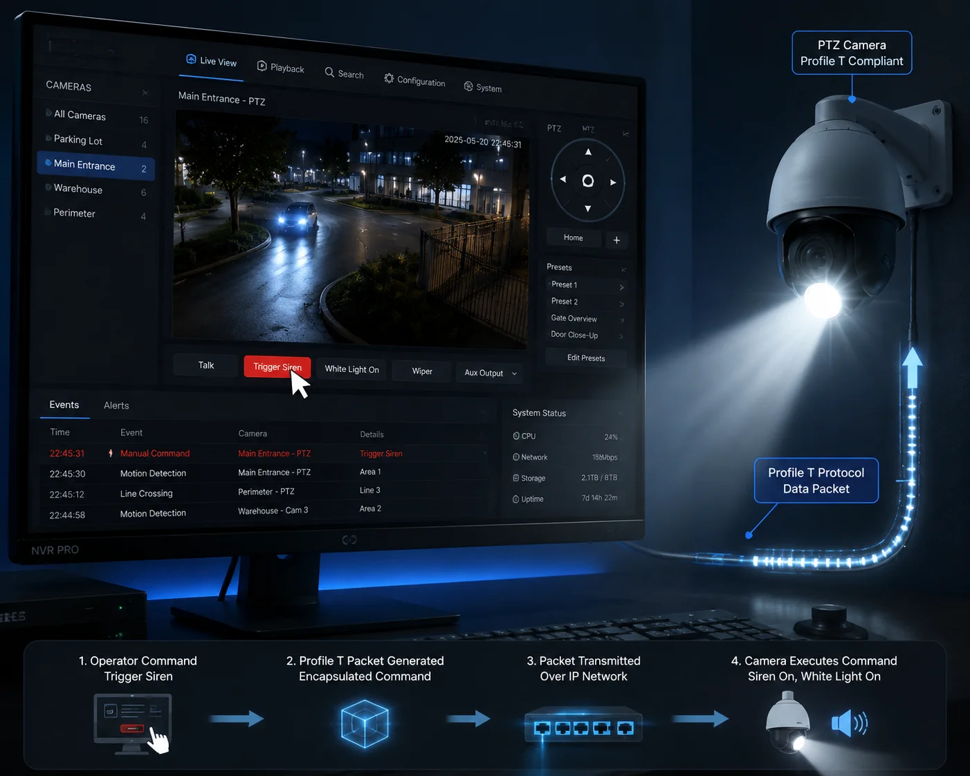 NVR software triggering camera siren via ONVIF
How the Trigger Command Actually Works
When your NVR software wants to activate the camera’s siren, it does not send an audio file. Instead, it sends a small SOAP-based XML command1 to the camera’s ONVIF service endpoint. This command tells the camera to close (or open) a specific relay output. The camera’s internal firmware then maps that relay output to a physical action — turning on the siren, flashing the white light, or activating an external device wired to the alarm-out terminal.
Here is the basic flow:
- The VMS sends a
SetRelayOutputStaterequest to the camera. - The camera receives the command and validates the session credentials.
- The camera closes the relay circuit mapped to the siren.
- The siren activates.
- The camera sends back a confirmation response.
This sounds simple. But in practice, three things can go wrong.
Common Failure Points
| Failure Point | Root Cause | Fix |
|---|---|---|
| Siren does not activate | VMS did not enable “Event Subscription” during device setup | Go to device settings in VMS, enable alarm/event features manually |
| Command is sent but ignored | Camera’s I/O mode is set to “Schedule” instead of “Manual/Remote” | Switch I/O trigger mode to “Network Command” in camera web UI |
| Intermittent triggering | ONVIF session times out due to network instability | Shorten the keep-alive interval to 10–15 seconds |
Profile S vs. Profile T — Why It Matters
Not all ONVIF profiles are equal. Profile S handles basic video streaming and simple alarm input notifications. But if you want to remotely control the relay output — to trigger a siren or a searchlight — you need Profile T. Profile T was designed for advanced event handling. It supports bidirectional I/O control, which means the VMS can both read the state and write a new state to the relay.
I always tell my clients: before you commit to a VMS platform, check if it supports Profile T event handling. If it only supports Profile S, you can still see alarms come in, but you cannot push commands back out to the camera. That is a one-way street, and it is not enough for active deterrence.
The HTTP API Fallback
What if your NVR software has poor ONVIF compatibility? This happens more often than you think, especially with smaller or regional VMS brands. In that case, our cameras also support a direct HTTP API2. You can send a simple HTTP GET request like http://[camera-IP]/ISAPI/System/IO/outputs/1/trigger to force the siren on. No ONVIF handshake needed. No XML parsing. Just a URL. This is lighter, faster, and more reliable over 4G connections with limited bandwidth.
Is the Alarm Output State (On/Off) Visible to the VMS in Real-Time?
I once had a client in Canada who wired a gate lock to the camera’s alarm output. The gate would open, but his VMS showed the relay as “Off.” He thought the system was broken. It was not — his VMS just was not reading the state correctly.
Yes, the alarm output state is visible to the VMS in real time, provided the camera supports ONVIF Profile T and the VMS subscribes to the camera’s event notification channel. The camera pushes state changes as XML event messages the moment the relay toggles.
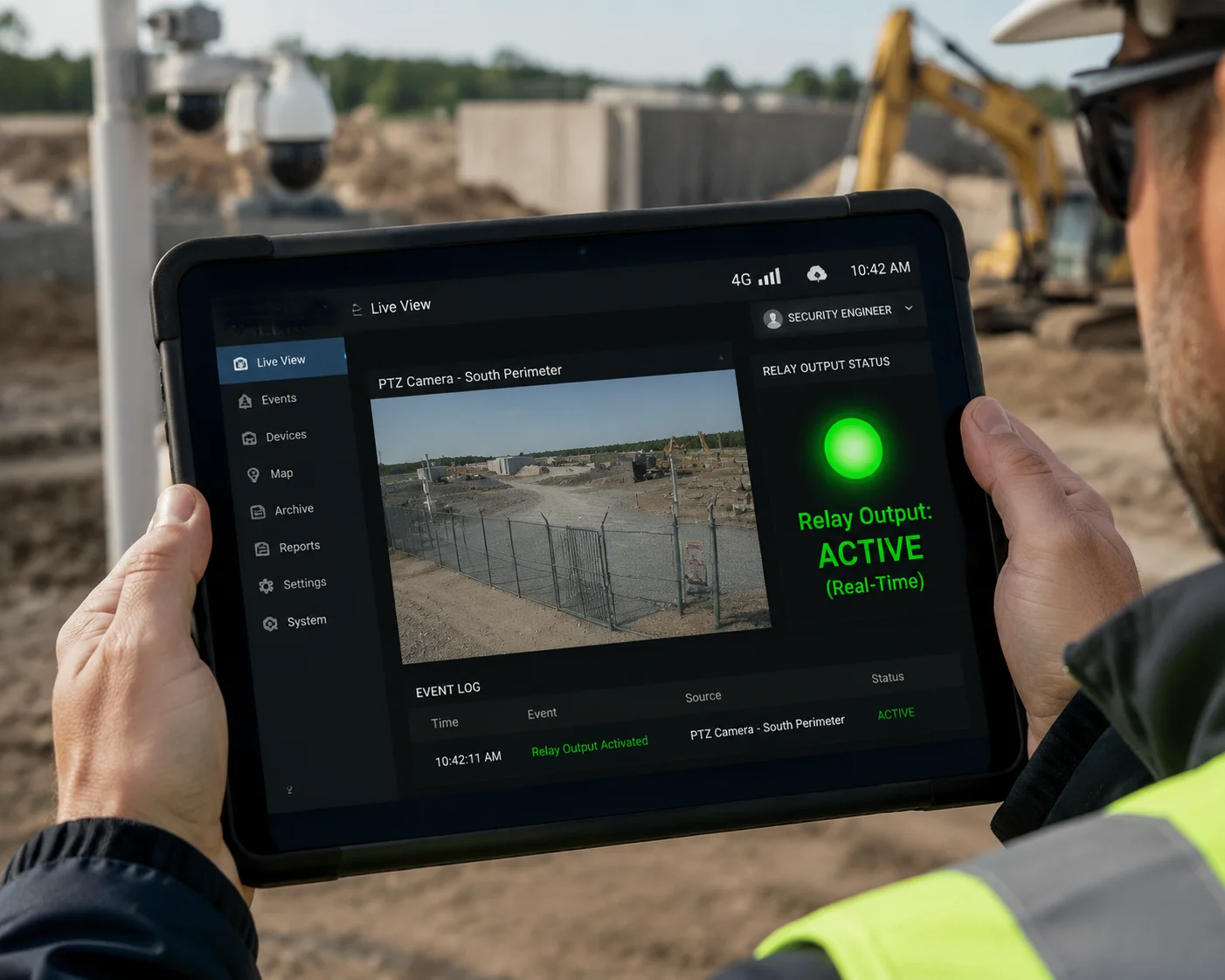 VMS showing real-time alarm output state from PTZ camera
Push vs. Pull — Two Ways to Read the State
ONVIF supports two methods for the VMS to know the current state of the alarm output:
Push (Event Subscription): The VMS subscribes to the camera’s event service. When the relay state changes — from idle to active, or active to idle — the camera immediately sends a notification. This is the fastest method. Latency is typically under 500 milliseconds on a local network.
Pull (Polling): The VMS periodically asks the camera, “What is the current state of your relay?” This is slower. The delay depends on the polling interval. If the VMS polls every 5 seconds, you could miss a brief relay activation entirely.
Why the State Might Not Show Up
There are several reasons why your VMS might not display the relay state, even though the camera is working correctly.
| Symptom | Likely Cause | Solution |
|---|---|---|
| State always shows “Unknown” | VMS does not support Profile T event parsing | Upgrade VMS or switch to a Profile T-compatible platform |
| State updates with a 5–10 second delay | VMS is using Pull mode instead of Push | Switch to Push-based event subscription in VMS settings |
| State shows “Off” even when relay is active | I/O polarity mismatch (NO vs. NC) | Match the I/O mode in camera settings to the VMS expectation |
The NO/NC Polarity Trap
This is the most common “gotcha” I see in the field. The camera’s alarm output can be configured as Normally Open (NO) or Normally Closed (NC). If the camera is set to NC but the VMS interprets the signal as NO, the displayed state will be inverted. The relay is actually closed (active), but the VMS shows it as open (inactive). This does not mean anything is broken. It just means the two systems disagree on what “active” looks like.
The fix is simple: go into the camera’s web interface, find the I/O configuration page, and set the output mode to match what your VMS expects. Most professional VMS platforms default to NO logic. So if you are unsure, set the camera to NO as well.
The NO/NC Polarity3 Trap
This is the most common “gotcha” I see in the field. The camera’s alarm output can be configured as Normally Open (NO) or Normally Closed (NC). If the camera is set to NC but the VMS interprets the signal as NO, the displayed state will be inverted. The relay is actually closed (active), but the VMS shows it as open (inactive). This does not mean anything is broken. It just means the two systems disagree on what “active” looks like.
The fix is simple: go into the camera’s web interface, find the I/O configuration page, and set the output mode to match what your VMS expects. Most professional VMS platforms default to NO logic. So if you are unsure, set the camera to NO as well.
Real-Time State in 4G Deployments
On a wired LAN, real-time state feedback is straightforward. But on a 4G connection — especially in rural or remote sites — things get tricky. The ONVIF event subscription relies on a persistent TCP connection between the camera and the VMS. If the 4G signal drops for even a few seconds, that connection breaks. The VMS loses its subscription. It stops receiving state updates until it re-subscribes.
Our cameras handle this by supporting a configurable keep-alive heartbeat. I recommend setting it to 10 seconds for 4G deployments. If the VMS does not hear back within two heartbeat cycles, it automatically re-subscribes. This keeps the state feedback loop alive even on unstable networks.
Can I Link an ONVIF Soft-Trigger4 to the Camera’s External Relay for Gate Control?
Gate control is one of the most requested features from my integrator clients. They want to use the camera not just as a pair of eyes, but as a control node — opening gates, activating barriers, or unlocking doors. The question is whether ONVIF can handle that responsibility.
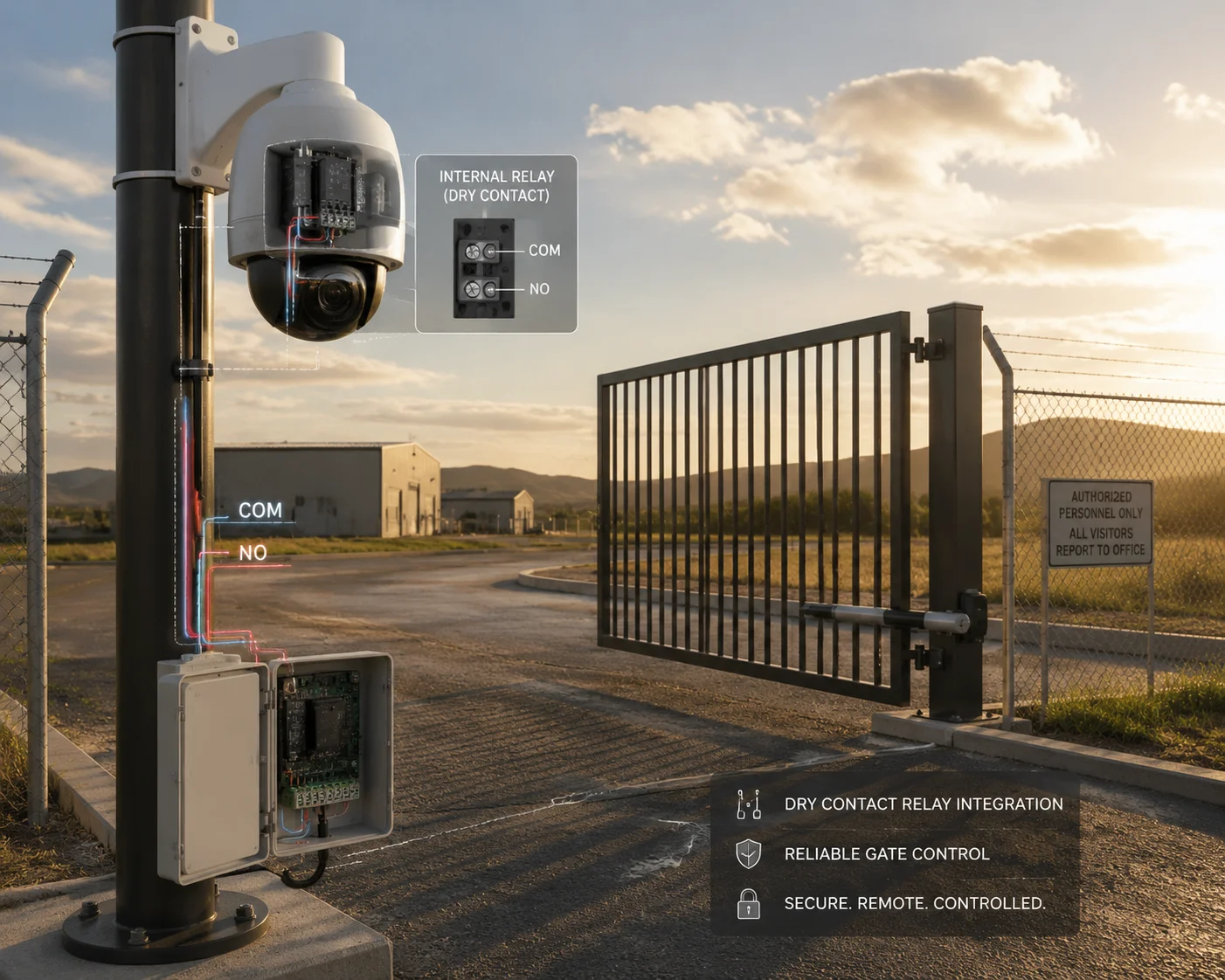
Yes, you can link an ONVIF soft-trigger to the camera’s external relay output for gate control. The VMS sends a SetRelayOutputState command, and the camera closes its dry-contact relay, which is wired to the gate controller. This works reliably on both LAN and 4G connections when configured correctly.
 ONVIF soft-trigger linked to external relay for gate control
How the Wiring Works
The camera’s alarm output terminal provides a dry-contact relay5. This means it acts like a simple switch — it either closes the circuit or opens it. It does not supply power. Your gate controller has its own power source. The camera’s relay just tells the gate controller when to activate.
Here is a typical wiring setup:
- Connect the camera’s Alarm Out terminal (two wires: COM and NO) to the gate controller’s trigger input.
- Set the camera’s I/O output mode to “Normally Open.”
- When the VMS sends the ONVIF trigger command, the relay closes.
- The gate controller sees a closed circuit and opens the gate.
- After the configured duration (e.g., 5 seconds), the relay opens again, and the gate closes.
Monostable vs. Bistable Relay Modes
This is a detail that many integrators overlook, and it can cause real problems in the field.
Monostable mode6: The relay closes for a set duration (e.g., 5 seconds) and then automatically returns to its default state. This is ideal for gate control. You send one command, the gate opens, and it closes by itself after the timer expires.
Bistable mode7: The relay stays in its new state until you send another command to change it back. This means if you trigger the relay to open the gate, the gate stays open forever — until you send a second command to close it. If your 4G connection drops between those two commands, you have a gate stuck open in a remote location.
I always recommend monostable mode for gate control. Set the duration to match your gate’s opening cycle — usually 5 to 10 seconds. This way, even if the network drops, the relay will automatically reset, and the gate will close.
Relay Specifications You Should Check
Before you wire the camera’s relay to a gate controller, verify that the relay can handle the electrical load. Here are the specs for our PTZ cameras:
| Parameter | Specification |
|---|---|
| Relay Type | Dry contact (NO/NC selectable) |
| Max Switching Voltage | 30V DC / 125V AC |
| Max Switching Current | 1A |
| Max Switching Power | 30W DC / 62.5VA AC |
| Relay Mode | Monostable (timed) / Bistable (latched) |
If your gate controller requires more than 1A to trigger, you will need an intermediate relay between the camera and the gate controller. This is standard practice in industrial installations. The camera’s relay triggers the intermediate relay, and the intermediate relay handles the higher current load.
Security Considerations
Using a camera as a gate controller introduces a security concern. If someone gains access to the camera’s ONVIF interface, they could send a trigger command and open the gate remotely. To prevent this:
- Always change the default ONVIF credentials.
- Use HTTPS for the ONVIF service if your VMS supports it.
- Restrict ONVIF access to specific IP addresses using the camera’s IP filter.
- Disable ONVIF discovery mode after initial setup to prevent unauthorized devices from finding the camera on the network.
How Many Milliseconds of Latency Should I Expect When Triggering an I/O via ONVIF?
Latency is the invisible enemy of remote I/O control. When you press “trigger” in your VMS and the siren does not go off for three seconds, you start to wonder if the system is working at all. I have had clients call me in a panic because of this exact scenario.
On a wired LAN, expect 100 to 300 milliseconds of latency for ONVIF I/O triggering. On a 4G LTE connection, expect 500 to 1,500 milliseconds depending on signal strength and network congestion. In worst-case scenarios with poor 4G coverage, latency can exceed 3 seconds.
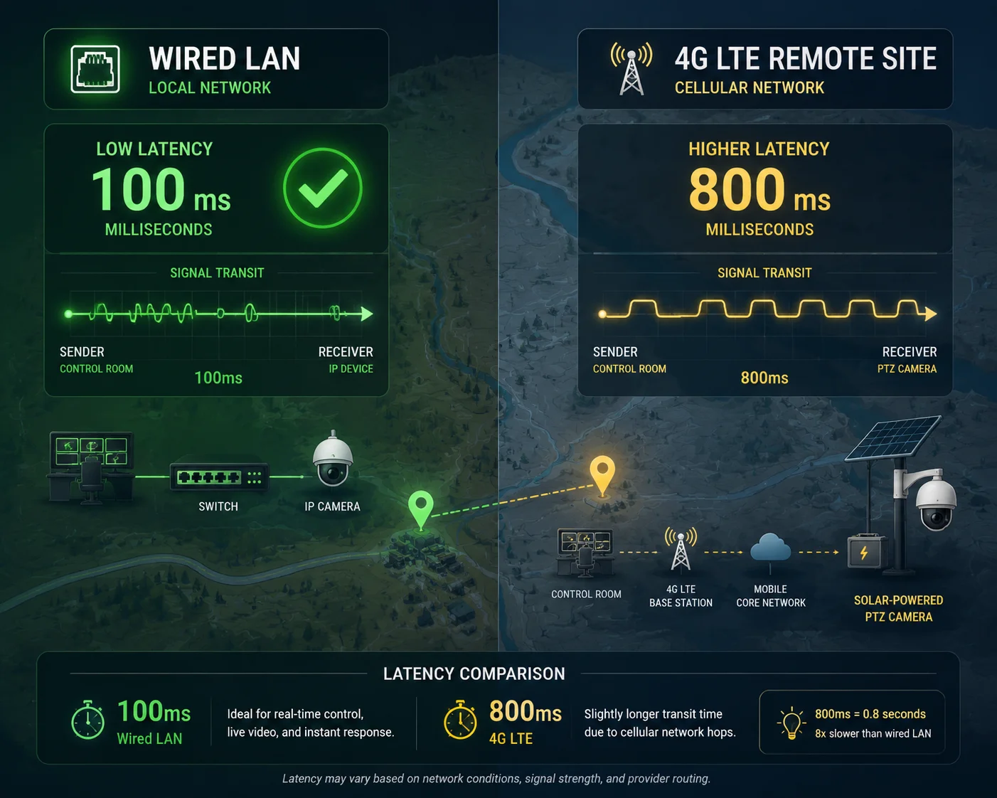 ONVIF I/O triggering latency measurement over LAN and 4G
Where the Latency Comes From
The total latency is not caused by one single bottleneck. It is the sum of several small delays across the entire chain. Let me break it down.
VMS Processing Delay (10–50ms): The VMS needs to build the SOAP XML command, authenticate the session, and send the packet. This is usually fast on modern hardware.
Network Transit Delay (1–500ms): On a LAN, this is under 5ms. On 4G, this varies wildly. A strong LTE signal in an urban area might give you 30–80ms. A weak signal in a rural area with one bar of coverage could push this to 500ms or more. And that is one way — the round trip doubles it.
Camera Processing Delay (20–100ms): The camera receives the command, parses the XML, validates the credentials, and then activates the relay. Our cameras use a dedicated I/O processor to minimize this step, but it still takes time.
Relay Mechanical Delay (5–15ms): The physical relay inside the camera has a small mechanical switching time. This is negligible compared to the other factors, but it exists.
Latency by Connection Type
Here is what I have measured in real deployments across different network conditions:
| Connection Type | Typical Latency | Worst Case | Best For |
|---|---|---|---|
| Wired LAN (Gigabit) | 100–200ms | 300ms | Fixed installations, data centers |
| Wi-Fi (5GHz, strong signal) | 150–400ms | 800ms | Temporary setups, indoor sites |
| 4G LTE (strong signal, urban) | 300–800ms | 1,500ms | Remote solar deployments |
| 4G LTE (weak signal, rural) | 800–2,000ms | 3,000ms+ | Off-grid farms, construction sites |
| Satellite (e.g., Starlink) | 500–1,200ms | 2,500ms | Extreme remote locations |
How to Reduce Latency in 4G Deployments
If you are deploying our 4G solar PTZ cameras in a remote location and latency is a concern, here are four things you can do:
Use the HTTP API instead of ONVIF. The ONVIF SOAP protocol is verbose. A single SetRelayOutputState command can be 2–3KB of XML. The HTTP API equivalent is a simple URL — under 100 bytes. On a slow 4G connection, that size difference matters. The HTTP API typically shaves 200–400ms off the total latency compared to ONVIF.
Enable TCP keep-alive8. Without keep-alive, every ONVIF command requires a new TCP handshake — that is an extra round trip. With keep-alive enabled, the connection stays open, and subsequent commands skip the handshake.
Use a high-gain 4G antenna. Our solar PTZ systems support external antenna connections. Replacing the stock antenna with a directional high-gain antenna (8–12dBi) can improve signal strength by 10–15dB, which directly reduces network latency.
Choose the right APN settings. Some cellular carriers offer private APN configurations with lower latency for IoT and M2M devices. Ask your carrier about dedicated APN options for security camera deployments.
When Latency Is Too High — The Fallback Plan
For applications where even 1 second of latency is unacceptable — like triggering a vehicle barrier at a checkpoint — I recommend a hybrid approach. Use the camera’s built-in AI (human/vehicle detection) to trigger the relay locally, with zero network dependency. The AI event fires the relay directly inside the camera’s firmware. Latency drops to under 50ms. The VMS still receives the event notification over ONVIF, but the critical action has already happened at the edge. This is the architecture I recommend for any safety-critical I/O application over 4G.
Conclusion
Our PTZ cameras support full bidirectional I/O control via ONVIF Profile T, with HTTP API as a reliable fallback — giving integrators the flexibility and redundancy they need for real-world deployments.
1. ONVIF control messages use SOAP XML, which can be verbose over slow networks. ↩︎ 2. A lightweight alternative to ONVIF for relay triggering, especially useful on 4G connections. ↩︎ 3. Mismatched Normally Open/Closed settings cause inverted relay state readings in the VMS. ↩︎ 4. A VMS-issued trigger that can be mapped to a physical relay for gate or barrier control. ↩︎ 5. A dry-contact relay acts as a simple switch without providing power — ideal for gate or siren control. ↩︎ 6. Monostable relay mode automatically returns to default after a set time, crucial for gate control. ↩︎ 7. Bistable relay mode stays latched until a second command is sent, requiring careful network reliability. ↩︎ 8. Maintains persistent ONVIF sessions, reducing handshake delays over unstable connections. ↩︎