
I’ve watched targets shrink to tiny dots on screen as they walk away from a fixed-zoom camera. That footage is useless for identification. This problem costs real money when you need evidence.
Yes, the Auto-Zoom function keeps the target at a consistent size in the frame. It uses a PID feedback loop1 to calculate the target’s pixel ratio in real time, then drives the zoom motor to compensate for distance changes. The result is a stable, identifiable image whether the subject is 10 meters or 500 meters away.
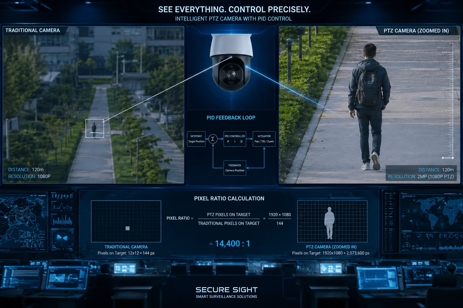
Below, I break down exactly how this works across different scenarios. I cover the zoom-out behavior when someone approaches, the 40X detail challenge at long range, the Target Fill Ratio settings, and the smoothness of zoom response during tracking. Each section goes deep into the engineering so you can make informed decisions for your next deployment.
Table of Contents
Will the Lens Automatically Zoom Out as a Person Approaches to Keep Their Full Body in View?
I’ve seen installers panic when a tracked person walks toward the camera and suddenly fills the entire frame. The system loses the target because it can’t see the edges anymore. This is a solved problem with proper auto-zoom logic.
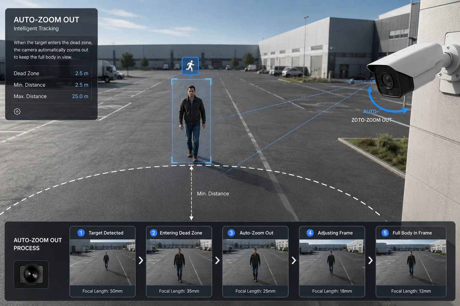
Yes, the lens zooms out automatically when a person approaches. The AI algorithm detects the target’s pixel height growing beyond the preset threshold and sends a zoom-out command to the motor. This keeps the full body visible in the frame at all times.
How the Zoom-Out Logic Works
The camera runs a continuous loop. Every frame, it measures how many pixels the target occupies. When someone walks toward the camera, their pixel size grows. The algorithm compares this size against a preset range, usually 10% to 25% of the frame height.
Once the target exceeds the upper limit, the system triggers a zoom-out command. The zoom motor pulls back until the target fits within the acceptable range again. This happens in under 500ms, so the transition feels natural on your monitor.
The Dead Zone Concept
The system does not react to every tiny change. If it did, the lens would constantly hunt back and forth. Engineers call this “zoom chattering.” To prevent it, the firmware includes a dead zone. The motor only moves when the target size drifts more than 5% away from the ideal value.
This dead zone serves two purposes. First, it keeps the video smooth for the operator. Second, it protects the zoom motor from excessive wear. In a 24/7 deployment, motor longevity matters.
Real-World Behavior Table
| Scenario | Target Distance | Zoom Action | Result |
|---|---|---|---|
| Person walking toward camera | 50m → 10m | Zoom Out (Wide) | Full body stays visible |
| Person standing still | Constant | No movement | Motor rests, no wear |
| Person running toward camera | 100m → 20m fast | Rapid Zoom Out | Algorithm predicts speed to stay ahead |
Why This Matters for System Integrators
If you deploy cameras at entry points, gates, or corridors, people will approach the camera directly. Without auto zoom-out, you get a few seconds of useful footage followed by a blurry close-up of someone’s chest. The AI tracker loses the bounding box and the system fails.
With proper zoom-out logic, the camera maintains a usable shot from the moment it acquires the target until the person passes underneath. This gives your VMS enough frames for facial recognition, gait analysis, or simple visual identification.
How Does the “Smart Zoom” Maintain a Clear 40X Detail of a Target Moving Away at 500m?
I’ve tested many cameras that claim 40X optical zoom2. Most of them lose focus completely when zooming in while tracking a moving target. The image turns into a blurry mess for 2-3 seconds. At 500 meters, those seconds mean you lose the target entirely.
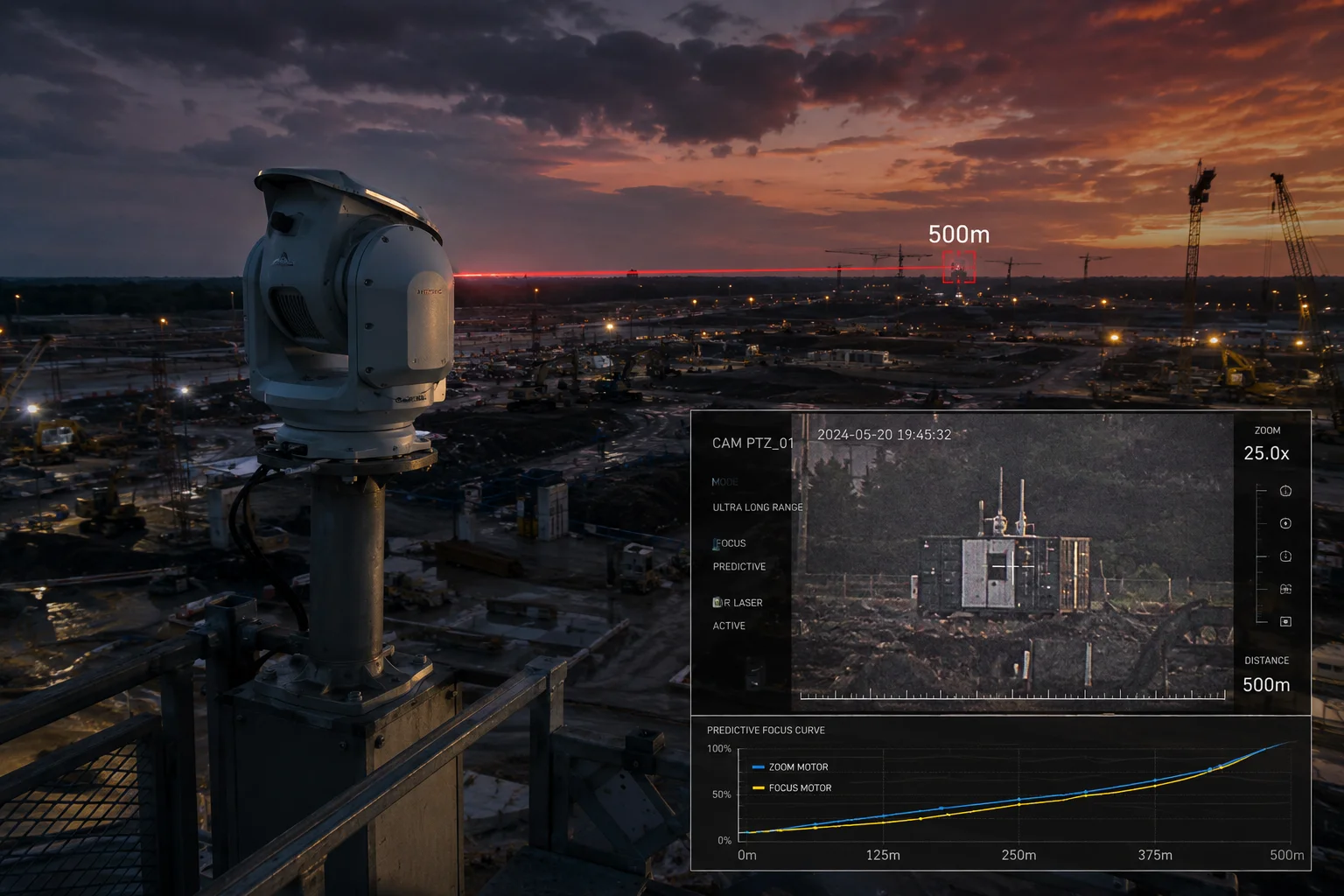
Smart Zoom at 40X maintains clarity through predictive focus algorithms that synchronize the focus motor with the zoom motor in real time. As the target moves away, the system zooms in while simultaneously adjusting focus based on calculated distance, not reactive hunting. This keeps the image sharp throughout the zoom transition.
The Core Challenge: Zoom-Focus Synchronization
At low magnification, focus errors are forgiving. The depth of field is wide enough that small mistakes don’t show. At 40X, the depth of field shrinks dramatically. A focus error of just a few millimeters on the lens assembly produces a completely unusable image.
Traditional cameras use a reactive approach. They zoom first, then hunt for focus. This creates a visible blur period. Our firmware uses a different method. It stores a zoom-focus curve3 in memory. This curve maps every zoom position to its correct focus position for a given distance. When the zoom motor moves, the focus motor moves simultaneously along this pre-calculated path.
Predictive Distance Estimation
The AI tracker doesn’t just know where the target is in the frame. It also estimates how fast the target is moving away. Using frame-to-frame size changes, the algorithm calculates the rate of distance increase. It then predicts where the target will be 200ms in the future and pre-positions the focus motor accordingly.
This prediction is critical at 500 meters. At that range, even walking speed (5 km/h) changes the required focus position noticeably between frames. Without prediction, the system is always one step behind.
Performance at Different Ranges
| Range | Zoom Level Used | Focus Method | Image Quality |
|---|---|---|---|
| 0-100m | 1X-10X | Standard autofocus | Excellent |
| 100-300m | 10X-25X | Curve-based sync | Very good |
| 300-500m | 25X-40X | Predictive + curve sync | Good (requires stable mount) |
| 500m+ | 40X max | Predictive + manual fine-tune | Acceptable in low wind |
Laser IR Coordination at Night
At 500 meters in darkness, you need active illumination. The laser IR module4 must zoom its beam angle to match the camera’s field of view. When the camera zooms to 40X, the laser narrows its beam to concentrate all its power on the small area the camera sees. This coordination happens automatically through the same control bus.
If the laser angle doesn’t match the camera zoom, you get one of two problems. Either the laser is too wide and the target is dimly lit. Or the laser is too narrow and the target moves out of the illuminated zone. Both situations cause tracking failure.
Vibration and Atmospheric Effects
At 40X and 500 meters, two external factors degrade image quality. First, any vibration in the mounting structure gets amplified 40 times. A pole swaying 0.1 degrees moves the image several meters at that range. Second, atmospheric heat shimmer distorts the light path.
Good installations use rigid wall mounts or heavy-duty poles with vibration dampeners. The camera firmware also includes digital stabilization5 that compensates for small movements. But physics sets hard limits here. No algorithm can fix severe atmospheric distortion on a hot day.
Can I Set a “Target Fill Ratio” (e.g., 30% of Screen) for the Auto-Zoom Algorithm?
I’ve worked with clients who need different zoom behaviors for different sites. A casino wants tight face shots. A construction site wants to see the whole person plus their surroundings. One fixed setting doesn’t work for everyone.
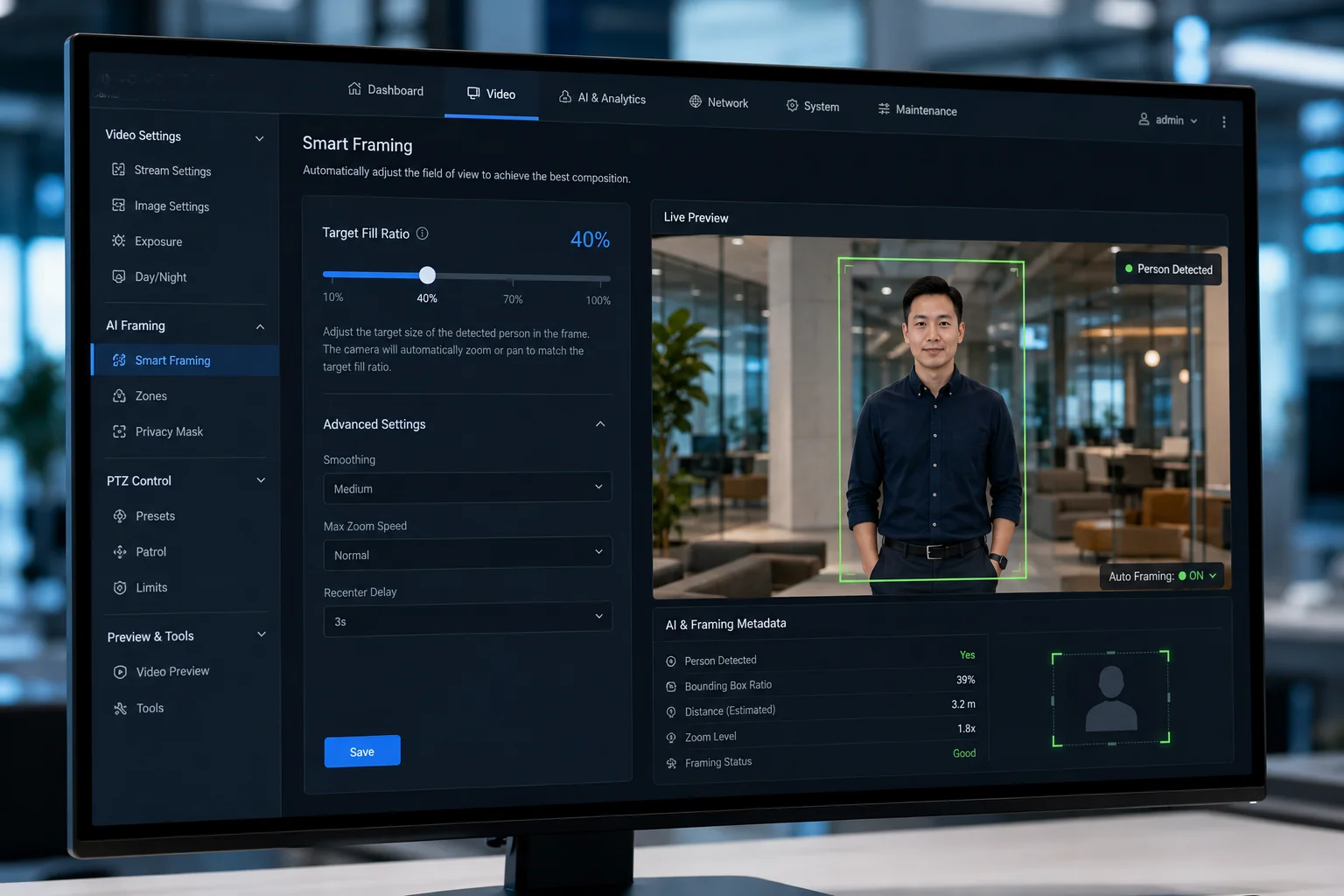
Yes, you can set a Target Fill Ratio through the camera’s web interface or API. This parameter tells the auto-zoom algorithm what percentage of the frame the target should occupy. Common settings range from 10% for context-rich views to 50% for identification-focused close-ups.
Understanding Fill Ratio Modes
The fill ratio is the single most important parameter in auto-zoom configuration. It determines the balance between detail and context. A higher ratio means more pixels on the target, which helps AI recognition algorithms. A lower ratio means more background visible, which helps operators understand the scene.
Most professional PTZ cameras offer this as a slider or numeric input in the configuration panel. Some systems label it differently. You might see “Target Size,” “Zoom Aggressiveness,” or “Detail Level.” They all control the same thing.
Mode Comparison
| Mode Name | Fill Ratio | Best For | Trade-off |
|---|---|---|---|
| Detail Mode | 40%-50% | Face recognition, license plates | Target can exit frame if moving fast |
| Balanced Mode | 20%-30% | General security, evidence capture | Good balance of detail and context |
| Context Mode | 10%-15% | Wide area monitoring, crowd tracking | Less detail per person |
How to Choose the Right Setting
Think about what happens after the camera captures the footage. If your client needs to identify faces for access control or forensic review, set the ratio higher. The AI needs at least 80 pixels between the eyes for reliable face matching. At 30% fill ratio on a 1080p camera, a person’s face gets roughly 60-80 pixels of width. That’s borderline. Push it to 40-50% if face ID is the priority.
If your client cares more about understanding what happened in an incident, keep the ratio at 15-20%. This shows the target plus their surroundings. You can see if they picked something up, interacted with another person, or entered a vehicle. Context tells the story.
Dynamic Fill Ratio Switching
Some advanced deployments use rules to switch fill ratios automatically. For example, during normal patrol mode, the camera uses 15% fill ratio for wide coverage. When the AI detects an alarm event like perimeter intrusion, it switches to 40% to capture maximum detail of the intruder.
This switching happens through the camera’s event-action system. You configure it as: “When alarm triggers, set fill ratio to 40% and enable auto-track.” After the event ends, it reverts to the patrol setting. This gives you the best of both worlds without manual intervention.
API Integration for Custom Workflows
For system integrators building custom VMS solutions, the fill ratio is accessible through ONVIF6 or the camera’s proprietary API. You can change it programmatically based on external inputs. Time of day, alarm zone, target classification (person vs. vehicle), or operator command can all trigger different fill ratios.
This flexibility matters when you’re deploying hundreds of cameras across a project. You don’t want to manually configure each one through the web interface. A script that pushes the right profile to each camera based on its location saves hours of setup time.
Is the Zoom Response Smooth Enough to Prevent Motion Blur During the Tracking Process?
I’ve reviewed footage from cheap PTZ cameras where every zoom adjustment creates a visible jerk. The image smears for a moment, the encoder struggles, and the recording shows artifacts. This is not acceptable for evidence-grade video.
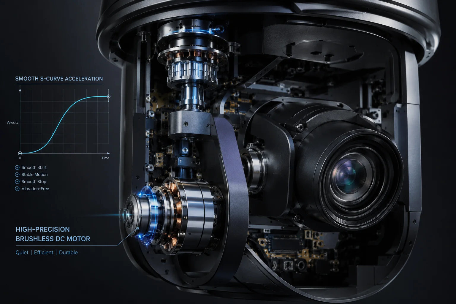
Yes, the zoom response is smooth enough to prevent motion blur. The motor uses variable-speed control that accelerates and decelerates gradually rather than jumping between positions. Combined with electronic image stabilization and a minimum shutter speed lock, the system produces clean frames even during active zoom transitions.
Why Zoom Causes Blur in the First Place
Motion blur during zoom comes from two sources. First, the physical movement of lens elements changes the optical path while the sensor is exposing a frame. If the zoom motor moves too fast relative to the shutter speed, the image smears radially from the center outward. Second, the mechanical vibration from the motor itself can shake the entire lens assembly.
Professional-grade zoom motors solve both problems. They use brushless DC motors7 with micro-step control. Instead of jumping from one zoom position to another, the motor glides smoothly through every intermediate position. The acceleration curve follows a trapezoidal or S-curve profile, which eliminates sudden jerks.
Shutter Speed and Zoom Speed Relationship
The camera firmware coordinates shutter speed with zoom activity. During a zoom transition, the system can temporarily increase the shutter speed to freeze any residual motion. On a bright day, this is easy. The camera has plenty of light to work with. At night, it’s harder because faster shutter speeds mean darker images.
This is where the laser IR module helps. By providing active illumination, it gives the sensor enough light to maintain a fast shutter speed even in total darkness. The result is sharp frames during zoom transitions regardless of ambient lighting conditions.
The 4G Streaming Consideration
When you stream over 4G LTE, the video encoder compresses each frame. Rapid zoom changes create high-complexity frames that are harder to compress efficiently. The bitrate spikes, and on a bandwidth-limited connection, you might see compression artifacts that look like blur but are actually encoding issues.
To handle this, the firmware limits zoom speed when it detects a bandwidth-constrained connection. It prioritizes image quality over zoom responsiveness. The zoom still reaches its target position, but it takes slightly longer to get there. For most tracking scenarios, this 200-300ms difference is invisible to the operator.
Zoom Speed Settings for Different Networks
Smart configuration matches zoom behavior to your network conditions:
- Fiber/Ethernet (unlimited bandwidth): Maximum zoom speed enabled. The encoder can handle the complexity.
- 4G LTE (10-30 Mbps): Medium zoom speed. Smooth enough for tracking, gentle enough for the encoder.
- 4G in weak signal areas (2-5 Mbps): Slow zoom speed. Prioritizes frame clarity over tracking aggressiveness.
Motor Longevity and Smooth Operation
A zoom motor in a 24/7 tracking camera might execute thousands of zoom cycles per day. If each cycle involves harsh start-stop movements, the motor wears out within months. Smooth acceleration profiles extend motor life significantly.
Our cameras use a closed-loop motor control8 system. A position encoder on the zoom motor reports its exact position back to the controller. This feedback loop ensures the motor never overshoots its target position, which would cause a visible bounce in the image. The motor arrives at its destination cleanly, every time.
This matters for your total cost of ownership. A camera that needs motor replacement after one year costs more in truck rolls and downtime than a camera that runs reliably for five years. The smooth zoom design isn’t just about image quality. It’s about reducing your maintenance burden in remote deployments where sending a technician costs hundreds of dollars per visit.
Conclusion
Auto-Zoom keeps your target at a consistent size by combining real-time AI measurement, predictive focus, configurable fill ratios, and smooth motor control. It turns raw PTZ hardware into an intelligent tracking system that delivers usable footage at any range.
1. Explains how PID controllers maintain stable output by adjusting proportional, integral, and derivative terms. ↩︎ 2. Explains the difference between optical and digital zoom, and why optical zoom preserves image quality. ↩︎ 3. Explains how pre-mapped zoom-to-focus positions enable synchronized lens movement. ↩︎ 4. Describes how laser IR provides long-range illumination synchronized with camera zoom. ↩︎ 5. Explains how digital (electronic) stabilization compensates for small camera movements. ↩︎ 6. Explains the ONVIF standard for interoperability of IP-based security cameras. ↩︎ 7. Explains the advantages of brushless DC motors in precision movement applications. ↩︎ 8. Explains how feedback from position sensors improves motor accuracy and reduces overshoot. ↩︎