
I have seen 4G modules freeze in the field. The camera stays powered on, but the network is dead. Nobody can reach it. You drive hours to the site just to unplug a cable and plug it back in.
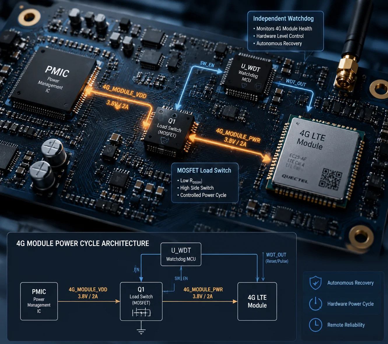
Yes, the motherboard can force a power-cycle on a crashed 4G module — but only if the hardware design includes a dedicated power-switch circuit and an independent watchdog MCU1. Without these two features, a frozen 4G module will stay frozen until someone physically cuts the power.
 4G module power cycle motherboard watchdog PTZ camera
Most low-cost PTZ boards do not have this ability. They treat the 4G module as a simple peripheral. When the module locks up, the main processor has no way to cut its power. The whole system must reboot — or worse, someone must visit the site. In this article, I will break down exactly how a properly designed motherboard detects a frozen modem, cuts its power, and brings it back to life — all without human hands.
Table of Contents
How Does the “Power Management IC” (PMIC) Detect a Frozen Modem That Is Still Drawing Current?
A frozen 4G module is tricky. It still pulls current from the power rail. The LEDs might still glow. From the outside, it looks alive. But it answers nothing.
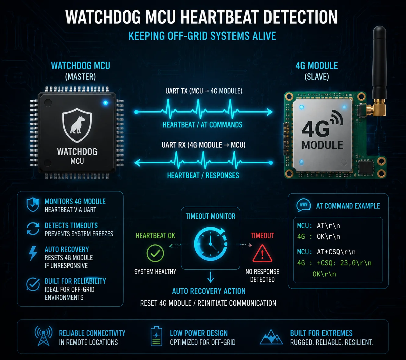
The motherboard does not rely on current sensing alone. Instead, a low-power MCU sends periodic AT commands2 to the 4G module over UART3. If the module fails to respond after several consecutive attempts, the MCU declares it “dead” and triggers the power-cut sequence.
 PMIC watchdog MCU 4G module heartbeat detection
Why Current Monitoring Alone Is Not Enough
You might think: “If the module crashes, its current draw will change.” Sometimes it does. But in many crash scenarios, the module keeps drawing 200–400 mA — a perfectly normal idle current. The PMIC sees nothing wrong. The voltage rail stays stable. The current looks fine. But the module’s firmware is stuck in an infinite loop or a protocol stack deadlock.
This is why good designs use a heartbeat-based detection4 method instead of — or in addition to — current monitoring.
How the Heartbeat System Works
Here is the typical detection flow:
| Step | Action | Timeout |
|---|---|---|
| 1 | MCU sends AT command via UART | Wait 3 seconds for response |
| 2 | No response → MCU retries | Retry up to 5 times (15 seconds total) |
| 3 | All retries fail → MCU sends AT+CFUN=1,1 (soft restart) | Wait 60 seconds for module to re-register |
| 4 | Still no response → MCU triggers hard power-cycle | Cut VCC for 2–5 seconds, then restore |
The MCU runs on its own clock. It does not depend on the main Linux processor. Even if the main CPU also hangs, the watchdog MCU keeps running. It is a completely independent circuit — often a tiny chip like an STM8 or an LPC810 that costs less than $0.50.
The Role of the PMIC in This Process
The PMIC itself does not “decide” to cut power. It simply provides the voltage rails. The decision-maker is the watchdog MCU. The MCU controls a MOSFET load switch5 sitting between the PMIC output and the 4G module’s VCC input. When the MCU pulls the MOSFET gate high, the switch opens. Power to the module drops to zero. After a timed delay (usually 2–5 seconds), the MCU releases the gate. Power returns. The module cold-boots from scratch.
Why the Delay Matters
You cannot just flick the power off and on instantly. The 4G module has internal capacitors. If you restore power too quickly, those capacitors still hold residual charge. The module’s internal state does not fully clear. It might boot right back into the same crashed state. A 2–5 second delay ensures every capacitor drains completely. The module returns to a true “factory power-on” condition. This is the difference between a real power-cycle and a fake one.
In our designs at Loyalty-Secu, we set this delay to 3 seconds by default. We tested shorter delays and found that some modules — especially in cold weather — need the full 3 seconds to discharge properly.
Is There a Dedicated “Reset Pin” Wired Between the CPU and the 4G Module’s Hardware?
I used to think the RESET pin was enough. Pull it low, wait a moment, release it, and the module restarts. It works — most of the time. But “most of the time” is not good enough for a camera sitting on a pole in the middle of a desert.
Yes, most 4G modules have a hardware RESET pin6, and a well-designed motherboard will wire it to a GPIO on the main CPU or watchdog MCU. But the RESET pin is only the first line of defense. It cannot fix every crash. A full VCC power-cut is the ultimate backup.
 4G module reset pin PWRKEY GPIO connection motherboard
What the RESET Pin Actually Does
The RESET pin triggers an internal restart of the module’s processor. It is similar to pressing the restart button on your computer. The module’s firmware reloads from flash memory. The baseband processor re-initializes. Network registration starts over.
For most software-level crashes — like a stuck dial-up process or a DNS lookup timeout — this works fine. The module comes back online in 20–40 seconds.
When the RESET Pin Fails
But there are situations where the RESET pin cannot help:
| Failure Type | What Happens | Can RESET Pin Fix It? |
|---|---|---|
| Latch-up | Static discharge or voltage spike causes a parasitic SCR effect inside the module. Current surges through unintended paths. | ❌ No. The internal circuit is electrically locked. Only a full power-cut can break the latch. |
| Voltage brownout lock | The module tried to transmit at high power, current spiked, voltage dropped below minimum, and the module entered an undefined state. | ❌ No. The module is stuck between “on” and “off.” The RESET logic itself may not function at this voltage. |
| Flash corruption | A power glitch during a firmware write corrupted the boot sector. The module cannot load its firmware at all. | ❌ No. The module loops endlessly at the bootloader stage. RESET just restarts the same broken loop. |
In all three cases, the only solution is to completely remove power from the module. This is why a MOSFET load switch on the VCC line is not optional — it is essential.
The Three-Stage Recovery Strategy
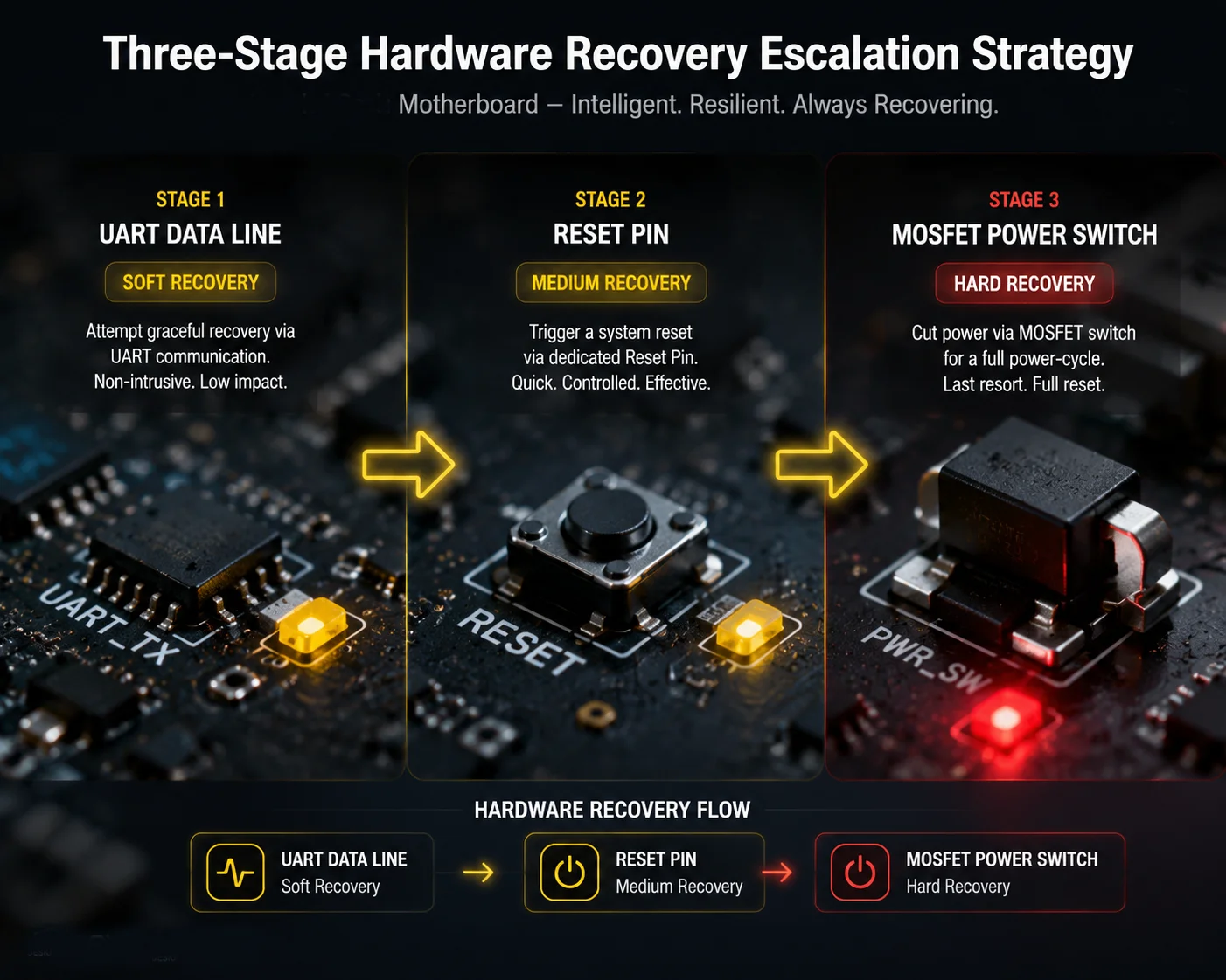
A properly designed motherboard uses a three-stage escalation:
- Stage 1 — Soft Reset: Send
AT+CFUN=1,1orAT+QPOWD=0via UART. This asks the module to restart itself politely. Wait 60 seconds. - Stage 2 — Pin Reset: Pull the RESET or PWRKEY pin low for 1 second, then release. This forces a hardware-level restart without cutting power. Wait 60 seconds.
- Stage 3 — Hard Power-Cycle: Cut VCC via the MOSFET switch. Hold for 3 seconds. Restore power. Wait 90 seconds for full boot and network registration.
If Stage 3 also fails after 3 consecutive attempts within 10 minutes, the system should stop trying and log a critical hardware fault. This prevents an endless reboot loop that could damage the module or drain a solar battery.
At Loyalty-Secu, we wire both the RESET pin and the PWRKEY pin7 to separate GPIOs on the watchdog MCU. This gives us independent control over each signal. We do not route them through the main Linux processor, because if Linux itself crashes, we still need the watchdog to act.
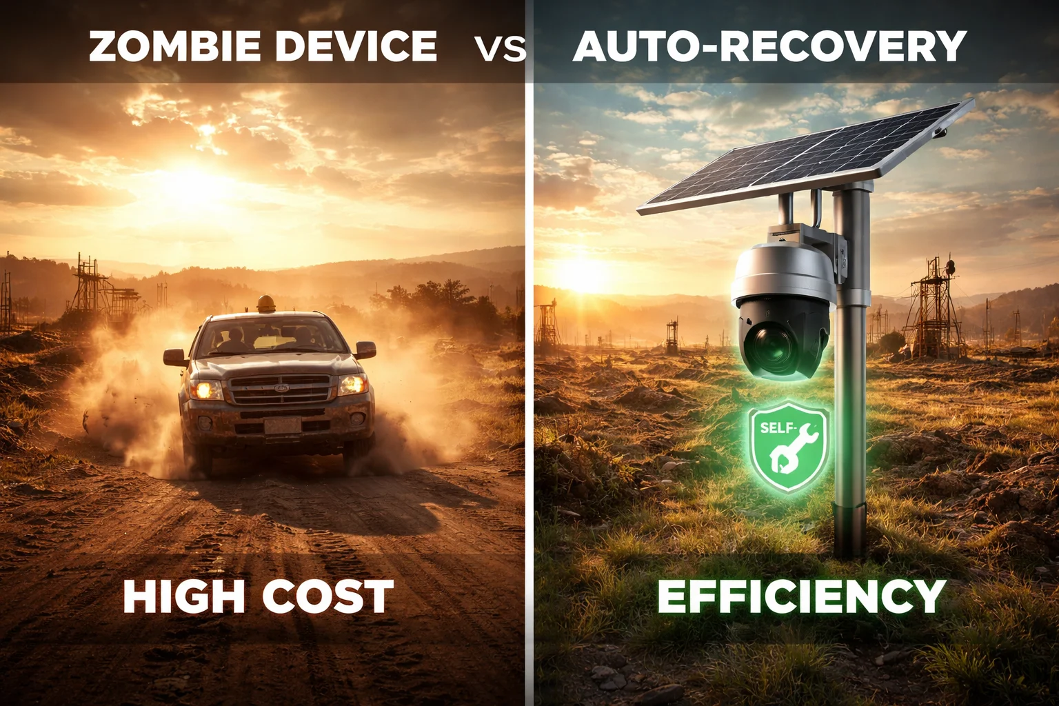
Will This Feature Prevent “Zombie Devices” That Stay Powered On but Are Unreachable?
“Zombie devices” — that is exactly what my clients call them. The solar panel keeps charging. The camera body stays warm. The status LED blinks green. But the 4G link is dead. The device is a ghost on the network. You cannot see it. You cannot control it. It just sits there, consuming power and doing nothing.
Yes, a motherboard with an independent watchdog and a 4G power-switch circuit will eliminate zombie devices. The watchdog detects the communication failure within 90 seconds and forces a full power-cycle. In most cases, the 4G module recovers and re-registers on the network within 3 minutes — with zero human intervention.
 zombie device solar PTZ camera 4G module auto recovery
Why Zombie Devices Are So Expensive
The device itself might cost $300–$500. But the cost of a zombie device is much higher than that. Consider this scenario: you deploy 50 solar PTZ cameras along a 200-kilometer pipeline in West Texas. Three months later, 4 of them go dark. Your monitoring center sees nothing from those 4 sites. You send a technician. The drive takes 6 hours round trip. The technician arrives, unplugs the power cable, waits 10 seconds, plugs it back in. The camera comes back online. Total cost of that “unplug and replug” visit: $800–$1,200 in labor, fuel, and lost productivity.
Now multiply that by 4 cameras. And it happens again next month. And the month after that.
How the Auto-Recovery Loop Works
A motherboard with proper watchdog design runs a continuous monitoring loop:
- Every 10 seconds, the watchdog MCU checks if the 4G module responds to a basic
ATcommand. - Every 30 seconds, it checks if the module has a valid IP address and can reach the cloud server (via a lightweight ping or MQTT keepalive).
- If both checks fail for 90 consecutive seconds, the recovery sequence begins.
What Happens During Recovery
The system follows the three-stage escalation I described earlier. But there is an important addition for zombie prevention: the watchdog also monitors the recovery itself.
If the module comes back online but drops again within 5 minutes, the watchdog counts this as an “unstable recovery.” After 3 unstable recoveries, the system switches to a low-power standby mode. It powers down the 4G module completely and waits for 30 minutes before trying again. This prevents battery drain on solar-powered systems.
Real-World Impact on Maintenance Costs
| Scenario | Without Auto Power-Cycle | With Auto Power-Cycle |
|---|---|---|
| Annual site visits per 50 cameras | 30–50 visits | 2–5 visits (only for true hardware failures) |
| Average cost per visit | $800–$1,200 | $800–$1,200 |
| Annual maintenance cost | $24,000–$60,000 | $1,600–$6,000 |
| Device uptime | 85–92% | 98–99.5% |
These numbers come from real feedback we receive from integrators deploying our solar PTZ systems in remote areas across the Middle East and North America. The auto power-cycle feature alone can cut annual field maintenance costs by 80% or more.
The “Zero-Maintenance” Promise
For off-grid deployments — solar-powered cameras on farms, construction sites, oil fields, or coastal cliffs — this feature is what makes “zero-maintenance” possible. The camera takes care of itself. It detects its own 4G failure. It fixes itself. It logs the event. And it goes back to work. No phone call. No truck roll. No downtime.
Does the Motherboard Log These “Crash-and-Recovery” Events for My Technical Audit?
When I talk to system integrators, they always ask the same question after I explain the auto-recovery feature: “That sounds great, but can I see what happened?” They need proof. They need logs. Their end clients — government agencies, utility companies, construction firms — require audit trails.
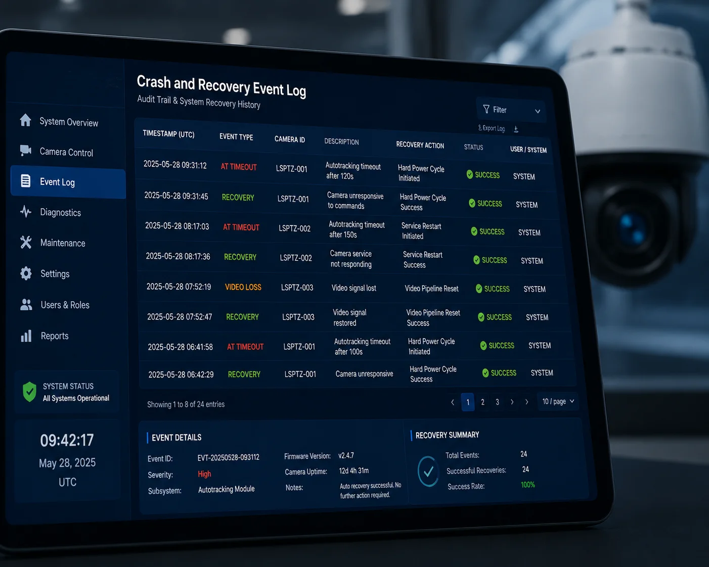
Yes, a well-designed motherboard logs every crash-and-recovery event with a timestamp, the failure type, the recovery stage that succeeded, and the module’s signal strength before and after the event. These logs are stored locally and can be pushed to a cloud server via MQTT or HTTP.
 crash recovery event log 4G PTZ camera audit trail
What Gets Logged
The watchdog MCU and the main processor work together to record detailed event data. A typical log entry includes:
- Timestamp: Date and time of the detected failure (synced via NTP or GPS).
- Failure type: AT timeout, heartbeat loss, UART error, or IP unreachable.
- Recovery stage: Which stage fixed the problem — soft reset, pin reset, or hard power-cycle.
- Duration: How long the module was offline before recovery completed.
- Signal quality: RSSI and SINR values before the crash and after recovery.
- Cumulative count: Total number of power-cycles since last system boot.
These logs are stored locally and can be pushed to a cloud server via MQTT8 or HTTP.
Why Logs Matter for Your Business
If you are a system integrator selling a 3-year maintenance contract, you need to prove that your system is reliable. When your client asks, “Why was Camera 17 offline for 4 minutes last Tuesday at 3 AM?” — you need an answer. Without logs, you have nothing. With logs, you can show them: “The 4G module lost its network registration due to a base station handover. The watchdog detected the failure in 90 seconds. A soft reset resolved it. Total downtime: 3 minutes 42 seconds. No data was lost because the camera cached 4 minutes of video locally and uploaded it after recovery.”
That level of transparency builds trust. It turns a potential complaint into a proof of quality.
How to Access the Logs
Most systems offer multiple access methods:
- Web interface: Log into the camera’s local web UI and download the event log as a CSV file.
- Cloud push: The camera pushes each event to your cloud platform via MQTT or HTTP POST in real time.
- ONVIF events: Some advanced firmwares map these recovery events to ONVIF9 event notifications, so your VMS (like Milestone or Blue Iris) can display them directly.
- Local storage: Logs are also written to the onboard eMMC or SD card, so even if the 4G link is down, the data is preserved.
What to Ask Your Supplier
When you evaluate a PTZ camera for remote deployment, ask these specific questions:
- “Does your motherboard have an independent watchdog MCU that monitors the 4G module?”
- “Can the watchdog physically cut power to the 4G module — not just send a reset signal?”
- “Where are the crash-and-recovery logs stored, and how can I access them remotely?”
- “What is the maximum number of auto power-cycles before the system stops and flags a hardware fault?”
If the supplier cannot answer these questions clearly, their board probably does not have this feature. And that means every frozen 4G module will require a truck roll.
At Loyalty-Secu, we build these capabilities into our motherboard design from the start. Our watchdog MCU, MOSFET power switch, and three-stage recovery logic are standard on all our 4G solar PTZ platforms. We also provide full event logs accessible via our cloud API or the camera’s local web interface. Because we control the entire vertical supply chain — from PCB design to final assembly — we can customize the watchdog timeout, recovery delays, and log formats to match your project requirements.
Conclusion
A motherboard can force a power-cycle on a crashed 4G module — but only if it has an independent watchdog MCU and a hardware power switch. Demand both in your next project spec.
1. A dedicated microcontroller that monitors system health and can force a hardware reset or power-cycle. ↩︎ 2. Standardised commands used to control modems, including cellular modules, over a serial interface. ↩︎ 3. A serial communication interface commonly used to connect microcontrollers to modems. ↩︎ 4. A monitoring technique that uses periodic signals to verify that a system or component is responsive. ↩︎ 5. A MOSFET-based circuit that can turn the power supply to a device on or off under logic control. ↩︎ 6. A hardware pin on a microcontroller or module that triggers a restart of its internal logic. ↩︎ 7. A control pin on cellular modules that is pulled low to initiate a power-on sequence; often used for resetting the module. ↩︎ 8. A lightweight publish-subscribe messaging protocol designed for IoT devices and low-bandwidth networks. ↩︎ 9. An open standard for IP-based security products, enabling interoperability between cameras and video management systems. ↩︎