
I’ve seen batteries arrive dead on the other side of the ocean. It’s a painful, expensive problem that kills deals before they even start.
A LiFePO4 battery1 can survive 3-6 months of sea freight without deep discharge2, but only if the system is physically disconnected and shipped at the correct state of charge. If any circuit stays in standby mode, parasitic drain will likely kill the pack before it reaches your warehouse.
Below, I break down the self-discharge math, the ideal shipping SOC, how to wake a sleeping battery, and how a proper storage mode prevents all of this. Let’s get into it.
Table of Contents
What Is the Monthly Self-Discharge Rate of Your LiFePO4 Packs During Storage?
Every battery loses charge just sitting on a shelf. The real question is: how fast, and does it matter over a 6-month voyage?
Our LiFePO4 cells self-discharge at roughly 1% to 3% per month when physically disconnected. Over 6 months, that means a maximum loss of about 18% — well within safe limits and far from the deep discharge danger zone.
 LiFePO4 battery self-discharge rate chart
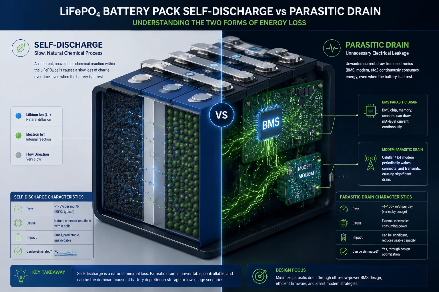
The Difference Between Self-Discharge and Parasitic Drain
This is where most people get confused. Self-discharge and parasitic drain are two completely different things, but they both eat your battery during transit.
Self-discharge is a chemical process. It happens inside the cell itself. No wires need to be connected. The lithium ions slowly migrate across the separator, and the voltage drops a tiny bit each month. For LiFePO4 chemistry, this rate is very low — much lower than lead-acid or even NMC lithium cells.
Parasitic drain is an electrical process. It happens when something is still connected to the battery. Even when your 4G solar PTZ camera is “off,” the BMS chip, the RTC clock, and the modem’s sleep circuit still pull current. This is usually between 5mA and 20mA.
The Math That Matters
Here’s a simple table showing what happens over time:
| Drain Source | Current Draw | Energy Lost in 3 Months | Energy Lost in 6 Months |
|---|---|---|---|
| Self-discharge only | ~0mA (chemical) | 3% – 9% of capacity | 6% – 18% of capacity |
| BMS standby | 2mA – 5mA | 4.3Ah – 10.8Ah | 8.6Ah – 21.6Ah |
| 4G modem sleep | 8mA – 15mA | 17.3Ah – 32.4Ah | 34.6Ah – 64.8Ah |
| Combined standby | 10mA – 20mA | 21.6Ah – 43.2Ah | 43.2Ah – 86.4Ah |
For a typical 40Ah battery pack in our solar PTZ systems, combined standby drain can empty the entire pack in under 6 months. That’s not a slow death — that’s a guaranteed kill.
Temperature Makes It Worse
Shipping containers crossing the equator can hit 60°C or higher inside. Heat speeds up chemical reactions. At 45°C, self-discharge roughly doubles compared to 25°C. At 60°C, it can triple. So that “safe” 3% per month becomes 6-9% per month in a hot container.
I always tell my clients: assume the worst-case temperature scenario when planning your shipping SOC. The ocean doesn’t have air conditioning.
What This Means for Your Project
If your system has a physical disconnect switch and ships at 50% SOC, you’ll arrive with 32-44% remaining. That’s perfectly healthy. If your system ships in standby mode at 30% SOC through a summer route, you’ll arrive with a dead battery and possibly permanent cell damage.
Do You Ship the Batteries at 30% or 50% SOC to Ensure Health During Long Transit?
Choosing the right shipping charge level is a balancing act between safety regulations and battery survival. Get it wrong, and you lose money on every shipment.
We ship our solar PTZ camera systems at 40-50% SOC for sea freight, with the battery physically disconnected. This gives enough buffer to survive 6 months of self-discharge while staying within international maritime safety guidelines for lithium batteries.
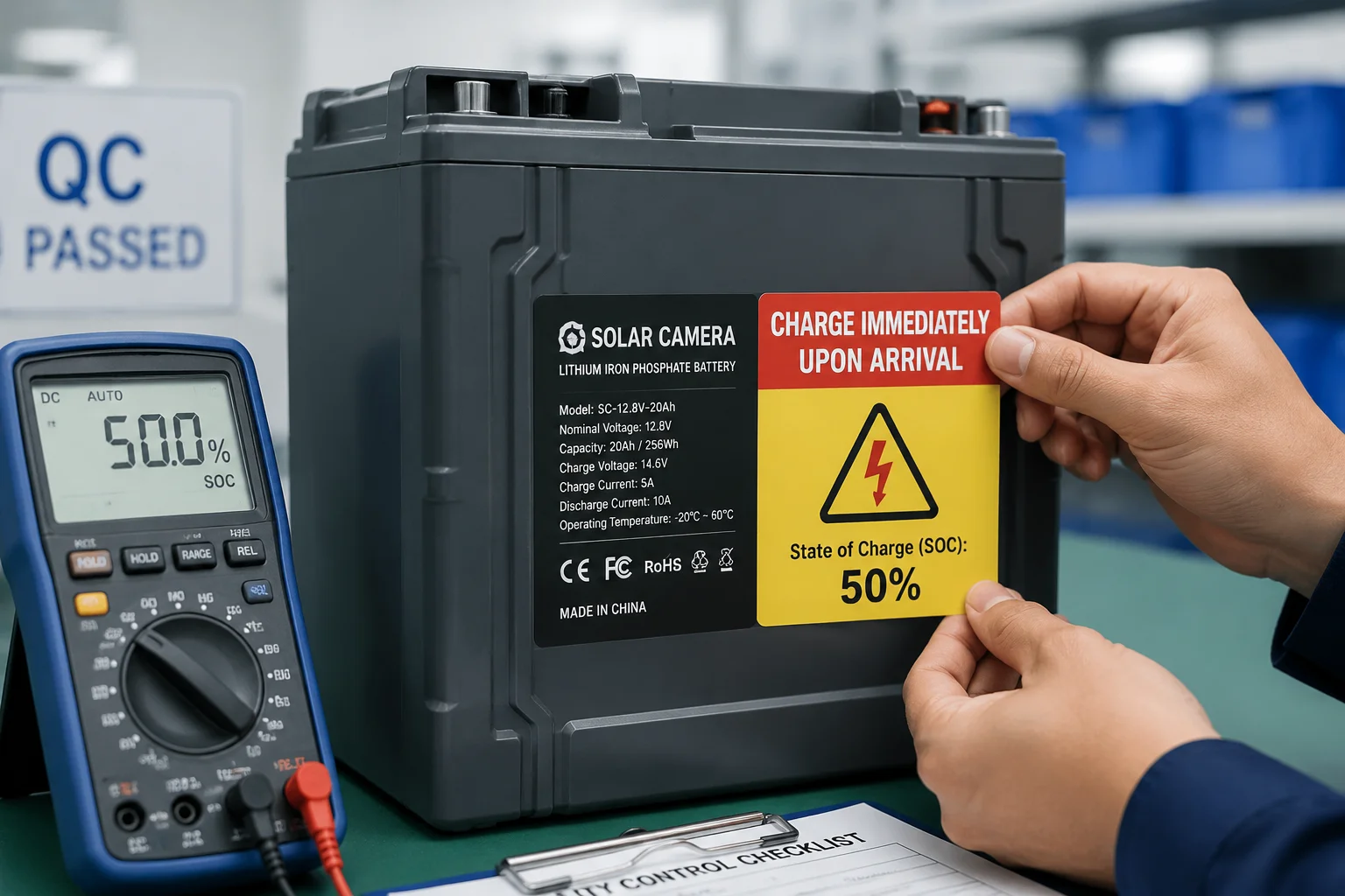 battery state of charge shipping label
Understanding the Regulatory Landscape
The rules around shipping lithium batteries come from two main bodies: ICAO3 (for air freight) and IMO4 (for sea freight).
For air freight, the rule is strict: batteries must be at or below 30% SOC. This is a hard limit from ICAO’s Technical Instructions. The logic is simple — a lower charge state means less energy available if something goes wrong, which reduces fire risk.
For sea freight, the rules are more flexible. The IMDG Code5 (International Maritime Dangerous Goods Code) requires proper packaging and labeling, but the SOC limit is less rigid than air freight. Most shipping lines accept 40-50% SOC for equipment with integrated batteries, as long as the battery is disconnected and properly packaged.
Why 30% SOC Is Risky for Long Voyages
Here’s the problem with shipping at exactly 30%:
| Starting SOC | After 3 Months (Best Case) | After 6 Months (Best Case) | After 6 Months (Worst Case – Hot Route) |
|---|---|---|---|
| 30% | 24% | 18% | 8% – 12% |
| 40% | 34% | 28% | 18% – 22% |
| 50% | 44% | 38% | 28% – 32% |
Most LiFePO4 BMS systems trigger a low-voltage cutoff6 at around 10-15% SOC (approximately 2.8V per cell). If you start at 30% and hit a hot route with delays, you’re flirting with that cutoff threshold. Once the BMS locks out, the battery enters protection mode. If it stays there too long, the cells can drop below 2.0V and suffer permanent capacity loss.
Our Standard Shipping Protocol
At , we follow a specific checklist before every shipment:
- Charge the battery to exactly 50% SOC (±2%)
- Record the open-circuit voltage (OCV) of each pack
- Engage the physical kill switch to disconnect all loads
- Apply a “CHARGE IMMEDIATELY UPON ARRIVAL” label in English and the destination language
- Include the OCV reading on the packing slip so the client can compare upon arrival
The 50% Sweet Spot
Why 50% and not higher? Two reasons. First, lithium cells are most chemically stable in the 30-60% range. Storing them at 100% accelerates calendar aging9. Second, even if regulations allow it, shipping at higher SOC increases the energy available in a thermal event. 50% gives us the best balance of safety margin, regulatory compliance, and battery longevity.
How Do I “Wake Up” a Battery That Has Entered an Emergency Low-Voltage Sleep Mode?
You open the box, flip the switch, and nothing happens. The LED doesn’t blink. The camera doesn’t boot. Don’t panic — this doesn’t always mean the battery is dead forever.
To wake a LiFePO4 battery from low-voltage sleep mode, connect a compatible charger at low current (0.1C or less) for 15-30 minutes. If the BMS has locked out, you may need to apply voltage directly to the charge port to “kick-start” the protection circuit back into operation.
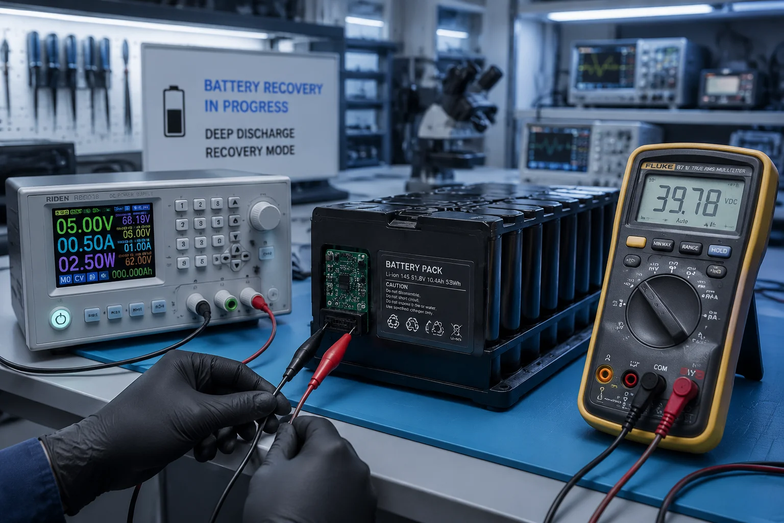 battery BMS wake up procedure
Why Batteries Enter Sleep Mode
The BMS (Battery Management System) is designed to protect the cells. When voltage drops below a set threshold — usually 2.5V to 2.8V per cell — the BMS disconnects the output MOSFET. This stops all current flow. It’s a safety feature, not a defect.
The problem is that once the BMS disconnects, it also stops monitoring in some designs. The cells continue to self-discharge (slowly), and without the BMS actively balancing them, individual cells can drift apart in voltage. One cell might sit at 2.6V while another drops to 2.3V. That unbalanced state makes recovery harder.
Step-by-Step Recovery Process
Here’s what I recommend when a client reports a “dead” battery after long transit:
Step 1: Measure the pack voltage. Use a multimeter on the main battery terminals. If you read above 10V on a 4S pack (4 cells in series), the cells are likely recoverable.
Step 2: Check individual cell voltages. If you have access to the balance connector or cell taps, measure each cell. Any cell below 2.0V may have permanent damage.
Step 3: Apply trickle charge. Connect a charger rated for LiFePO4 (14.6V for a 4S pack) and set it to the lowest current available. Many smart chargers won’t start if they detect voltage below their minimum threshold. In that case, you need a “dumb” power supply set to 14.0V with a current limit of 0.5A.
Step 4: Wait and watch. After 15-30 minutes of trickle charging, the cell voltages should rise above the BMS wake-up threshold. Once the BMS “wakes up,” it will reconnect the output and the charger can operate normally.
Step 5: Full charge and capacity test. After a full charge, run a discharge test to verify the pack still holds at least 80% of its rated capacity. If it doesn’t, the cells have suffered irreversible damage.
When Recovery Is Not Possible
If any cell has been below 2.0V for more than a few weeks, copper dissolution7 occurs inside the cell. This creates internal short circuits that cannot be repaired. The cell will show normal voltage after charging but will self-discharge rapidly — sometimes losing 10-20% per day. This battery must be replaced.
This is exactly why we install physical kill switches in all our solar PTZ systems. Prevention is always cheaper than replacement.
Can the BMS Handle a Long-Term “Storage Mode” to Prevent Any Parasitic Drain?
A smart BMS should do more than just protect against over-discharge. It should actively manage long-term storage. But not all BMS designs are equal.
Yes, our BMS supports a dedicated storage mode that reduces quiescent current8 to below 50 microamps — effectively eliminating parasitic drain. This mode is activated automatically when the physical kill switch is engaged, ensuring the battery remains healthy through months of warehousing or transit.
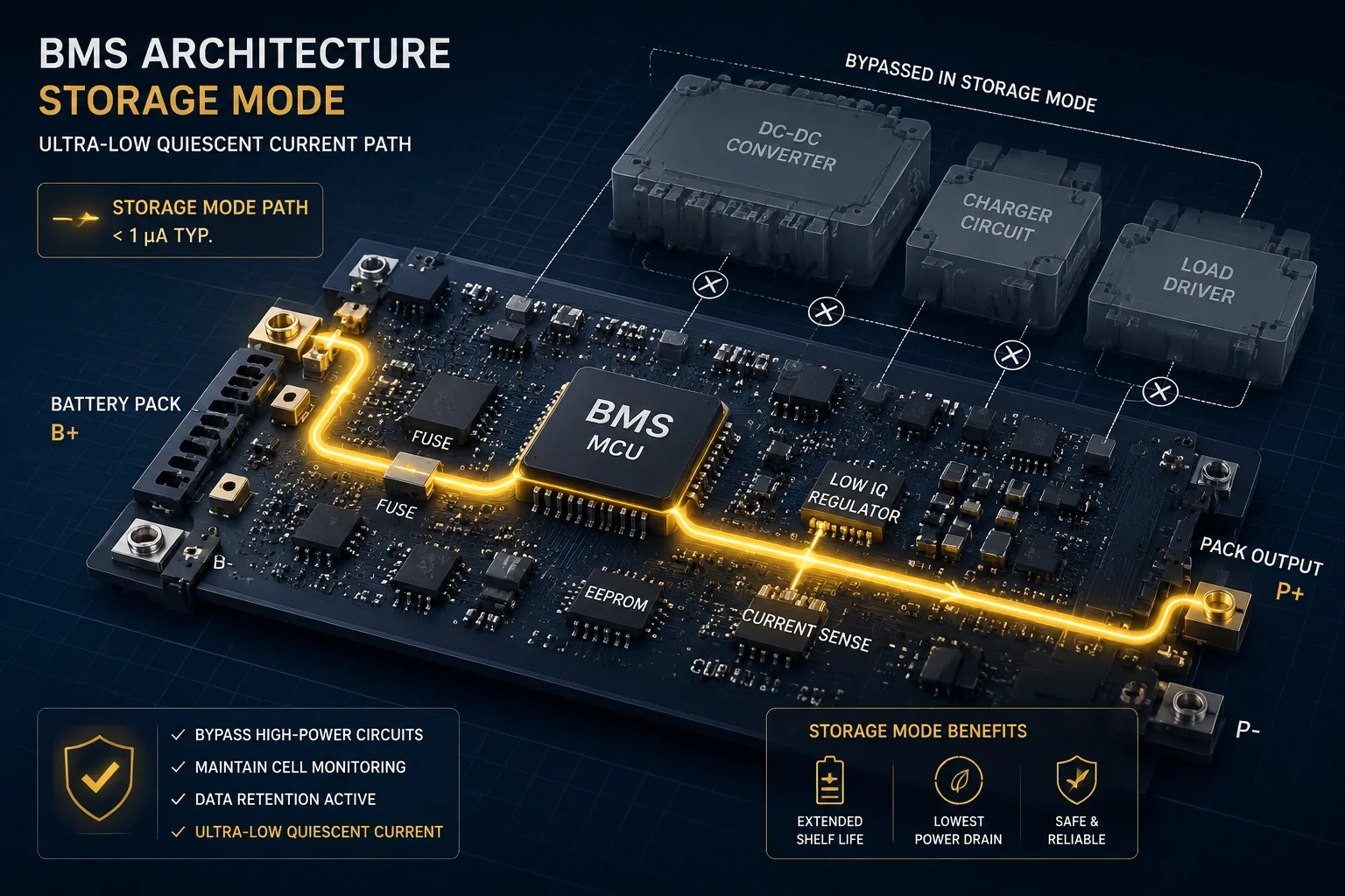 BMS storage mode circuit diagram
What “Storage Mode” Actually Means at the Circuit Level
A standard BMS in active mode performs several tasks continuously: it monitors cell voltages, checks temperature sensors, communicates with the host device, and keeps the protection MOSFETs in their correct state. All of this requires power — typically 1mA to 5mA from the battery itself.
In storage mode, the BMS shuts down everything except the most basic voltage comparator. This comparator uses almost no power (microamps, not milliamps). Its only job is to detect when a charger is connected, which triggers a full wake-up of the BMS.
The Three Levels of Power Isolation
| Level | Method | Quiescent Current | Use Case |
|---|---|---|---|
| Level 1: Software shutdown | Camera “off” via firmware | 5mA – 20mA | Short-term storage (days) |
| Level 2: BMS storage mode | BMS enters low-power state | 50µA – 200µA | Medium-term storage (weeks) |
| Level 3: Physical disconnect | Kill switch breaks the circuit | 0mA (true zero) | Long-term transit (months) |
For sea freight lasting 3-6 months, I always recommend Level 3. It’s the only way to guarantee zero drain. Level 2 is acceptable for warehouse storage where you can periodically check voltage. Level 1 is never acceptable for shipping — I’ve seen too many dead batteries arrive because someone thought “turning it off” was enough.
How Our System Implements This
In every solar PTZ system designed for export, we include:
- A physical blade-type disconnect between the battery and the main PCB
- A BMS with hardware storage mode that activates within 10 seconds of detecting zero load
- A bright orange tag on the disconnect switch that reads “CONNECT BEFORE POWER ON”
The physical disconnect is not a fancy feature. It’s a simple mechanical switch or a plug connector that breaks the circuit completely. No electrons flow. No drain occurs. The battery sits in pure chemical equilibrium until someone physically reconnects it.
Why Software-Only Solutions Fail
I’ve worked with integrators who asked: “Can’t we just add a firmware command to put everything to sleep?” The answer is technically yes, but practically no. Here’s why:
A microcontroller in deep sleep still draws 5-50 microamps. A voltage regulator still has quiescent current. A 4G modem in “power off” mode still maintains its SIM detection circuit. These tiny currents add up. Over 6 months, even 100 microamps means 0.43Ah lost — not dangerous by itself, but combined with self-discharge and temperature effects, it narrows your safety margin.
The physical switch eliminates all doubt. It’s the simplest, most reliable solution. And in my experience, simple solutions are the ones that actually work in the field.
Conclusion
Ship at 50% SOC, use a physical kill switch, and your LiFePO4 battery will survive any sea voyage. Skip these steps, and you’ll open boxes full of dead equipment.
1. Overview of LiFePO4 chemistry, advantages, and typical applications. ↩︎ 2. Explanation of deep discharge and its effects on lithium battery lifespan. ↩︎ 3. Official ICAO page for dangerous goods regulations including lithium battery shipping. ↩︎ 4. International Maritime Organization dangerous goods homepage. ↩︎ 5. Official publication page for the International Maritime Dangerous Goods Code. ↩︎ 6. Technical explanation of BMS low-voltage cutoff thresholds. ↩︎ 7. Research article on copper dissolution mechanisms in lithium-ion cells. ↩︎ 8. Texas Instruments application note on quiescent current in battery management ICs. ↩︎ 9. NREL research on calendar aging of lithium-ion batteries. ↩︎