
I have seen too many PTZ cameras come back from the field with burned-out 4G modules — and the entire mainboard had to be thrown away.
Using a Mini-PCIe or M.2 socket instead of soldering the 4G module directly onto the mainboard gives you modular flexibility. You can swap modules for different carriers, upgrade from 4G to 5G, replace a damaged modem on-site, and keep one universal mainboard design across all export markets.
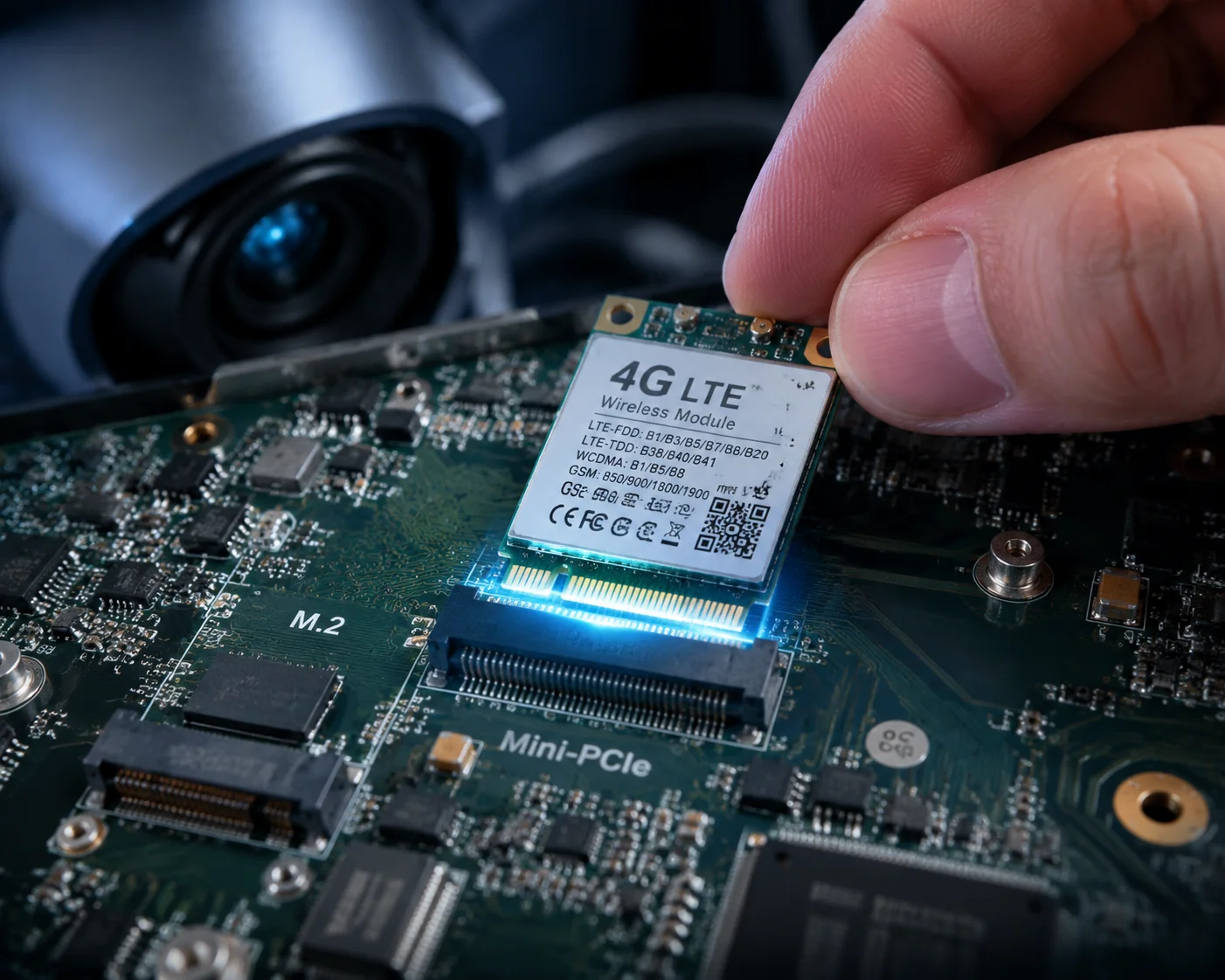 Mini-PCIe and M.2 modular interface on PTZ camera mainboard
At Loyalty-Secu, we build every solar PTZ camera around this plug-and-play principle. The reasons go far beyond simple convenience. They touch on inventory costs, field repair speed, certification strategy, thermal management, and long-term supply chain safety. In this article, I will walk you through the four most common questions I get from integrators and distributors in North America, Europe, and the Middle East — and show you why the socket approach wins every time.
Table of Contents
Can I Easily Upgrade My Cameras From 4G to 5G by Simply Swapping the M.2 Module Later?
I remember a distributor in Texas who bought 500 units of our Cat.4 solar PTZ cameras. One year later, his carrier rolled out 5G. He panicked.
Yes. If your PTZ camera uses an M.2 or Mini-PCIe socket, you can pull out the old Cat.4 module and plug in a Cat.6, Cat.12, or even a 5G module — without changing the mainboard, the optics, or the motor system. This is the fastest and cheapest upgrade path.
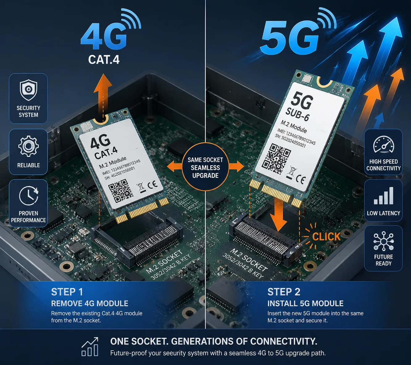 4G to 5G module upgrade on M.2 socket PTZ camera
Why This Matters for North American Buyers
The mobile network landscape in the U.S. and Canada moves fast. Carriers like Verizon, AT&T, and T-Mobile keep adding new frequency bands. They retire old ones. They push customers toward 5G4. If your camera has a soldered 4G module3, you are stuck with whatever bands and speed tier that module supports. To upgrade, you would need to redesign the entire PCB, re-do the FCC and PTCRB certifications, and probably change the mechanical housing too. That process takes 6–12 months and costs tens of thousands of dollars.
With a socket-based design, I just need to make sure the new module fits the same M.2 B-Key6 or Mini-PCIe footprint. Then my firmware team updates the driver. That is it. The camera is now on 5G.
The Real Cost Difference
Let me put some numbers on this. Suppose you have 1,000 cameras deployed across a solar farm project in Arizona.
| Upgrade Path | Socket-Based Design | Solder-Down Design |
|---|---|---|
| Hardware change | Swap M.2 module ($25–$45 each) | Replace entire mainboard ($120–$180 each) |
| Labor per unit | 10 minutes on-site | Ship back to factory, 4–6 weeks |
| Re-certification | Partial (reference module’s existing FCC ID) | Full FCC + PTCRB re-certification |
| Total cost for 1,000 units | ~$35,000–$55,000 | ~$180,000–$280,000+ |
| Downtime | Hours | Weeks to months |
The gap is massive. For a system integrator who bids on government or utility projects, this kind of flexibility is not optional. It is a requirement.
M.2 vs. Mini-PCIe for Future Bandwidth
Not all sockets are equal. Mini-PCIe1 has been the industry workhorse for years, but it tops out at PCIe x1 and USB 2.0 speeds. That is fine for Cat.4 or Cat.6 LTE. But 5G modules push data rates above 1 Gbps. They need PCIe x2 or even x4 lanes. M.22 supports those higher lane counts. So if you are planning a product line that needs to last five or more years, M.2 is the safer bet. I always tell my clients: choose M.2 today so you do not hit a bandwidth wall tomorrow.
How Does a Modular Interface Simplify Field Repairs if the Cellular Modem Is Damaged by a Surge?
I got a call at 2 a.m. once. A lightning storm in Oklahoma had fried the 4G modems in 30 cameras on a pipeline project. The client needed them back online within 48 hours.
A modular Mini-PCIe or M.2 interface lets a field technician replace a surge-damaged cellular modem in under 15 minutes — open the housing, unscrew one screw, pull the old module, insert a new one, and close up. No soldering iron. No factory return. No mainboard waste.
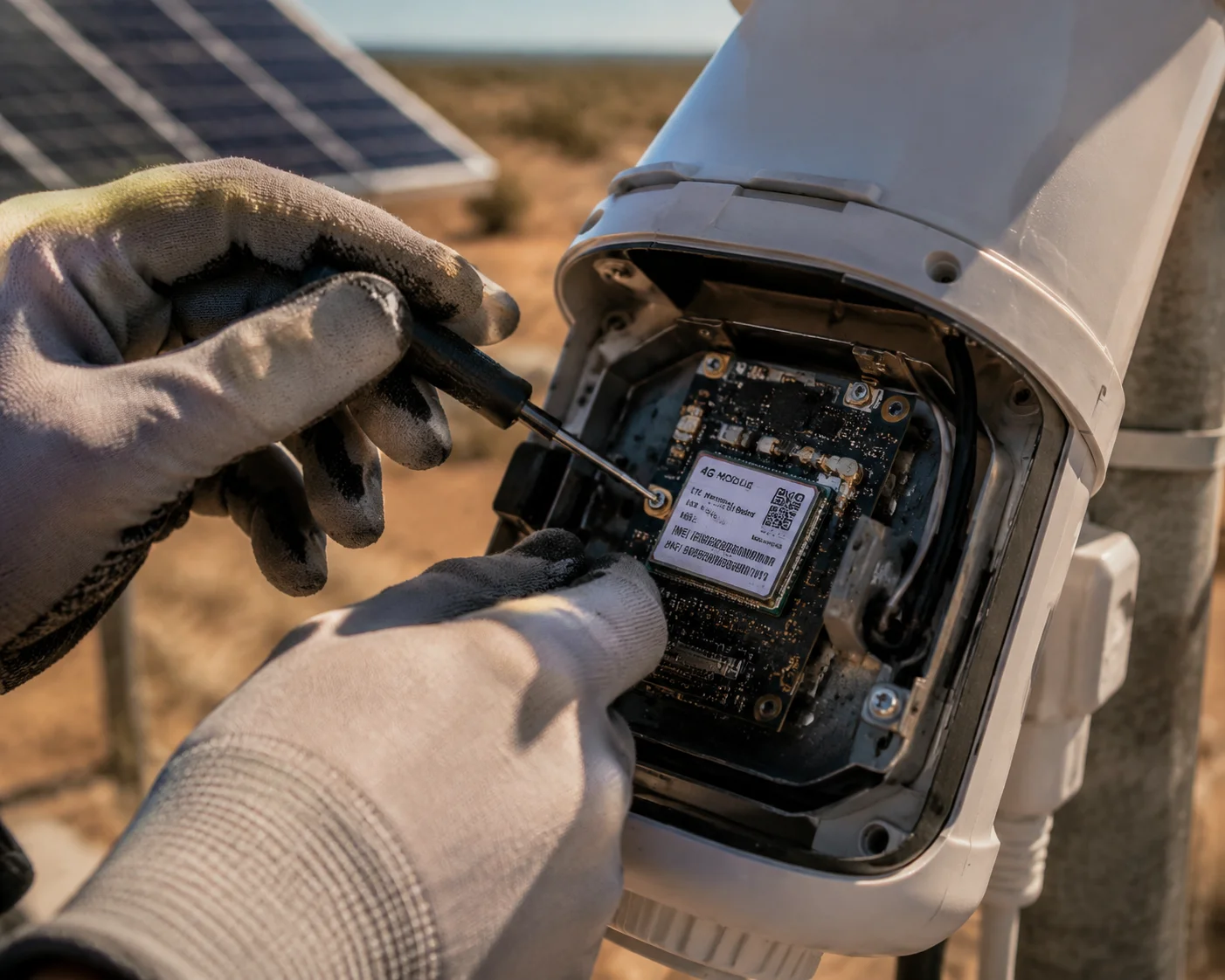 Field technician replacing Mini-PCIe 4G module in solar PTZ camera
The Real Enemy: Truck Roll Costs
In the U.S. security industry, people talk about “truck roll” costs. This is the total expense of sending a technician to a remote site. It includes the drive time, the labor, the fuel, and the lost productivity. For a solar PTZ camera on a ranch in Montana or on top of a construction crane in Houston, a single truck roll can cost $300–$800. If the technician arrives and finds out the mainboard is dead because the 4G module was soldered on and cannot be replaced, that truck roll was wasted. The camera goes back to the warehouse. Then it ships to China. Then it comes back weeks later. That is two or three truck rolls for one camera.
With a socket design, my Oklahoma client received 30 replacement modules by overnight FedEx. His local installer swapped them all in one day. Total downtime: 36 hours. Total cost: modules plus one day of labor. Compare that to shipping 30 complete cameras back across the Pacific Ocean.
What Kills the Module in the First Place?
Understanding the failure modes helps explain why the module — not the mainboard — is the most vulnerable part.
| Failure Cause | How It Damages the Module | Why the Mainboard Usually Survives |
|---|---|---|
| Lightning-induced surge | High voltage enters through the antenna cable and burns the RF front-end of the module | TVS diodes8 on the mainboard clamp the voltage before it reaches other chips |
| Prolonged high-temperature operation | The power amplifier inside the module overheats during continuous 4K video upload | The module sits on the socket, slightly raised above the board, so heat stays local |
| Carrier network reconfiguration | Constant band searching drains the module and stresses its firmware | The main SoC and image processor are on separate power rails |
| ESD during installation | A technician touches the antenna connector without grounding | The connector is on the module, not on the mainboard |
In each case, the module takes the hit. The mainboard, the image sensor, and the PTZ motor controller are fine. A socket design lets you replace only the part that failed. A solder-down design forces you to replace everything.
Spare Parts Strategy
For large deployments — say 200 to 2,000 cameras — I always recommend my clients keep 5% spare modules on hand. That is far cheaper than keeping 5% spare cameras. A Cat.45 module costs $20–$40. A complete 40X solar PTZ camera costs $600–$1,200. The math speaks for itself.
Does the Mechanical Socket Provide Better Thermal Isolation for the Core 4K Image Processor?
I once tested a competitor’s camera where the 4G module was soldered right next to the image sensor. At full 4K streaming over LTE, the sensor temperature climbed 12°C above normal. The video was full of noise.
Yes. A Mini-PCIe or M.2 socket physically raises the cellular module above the PCB surface and creates an air gap. This gap acts as a thermal buffer between the high-power RF transmitter and the heat-sensitive 4K image sensor, reducing thermal noise in the video.
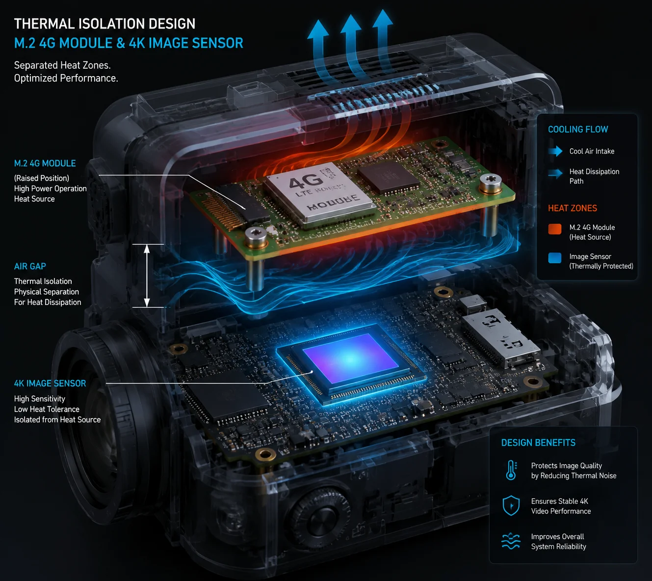 Thermal isolation between M.2 4G module and 4K image sensor on PTZ camera PCB
How Much Heat Does a 4G Module Produce?
When a 4G module uploads a 4K H.2657 video stream, its power amplifier can draw 2–4 watts of peak power. Most of that power turns into heat. On a small PCB inside a sealed outdoor enclosure, that heat has nowhere to go. It spreads through the copper layers of the board and reaches nearby components.
The image sensor is the most sensitive component on the board. When its temperature rises, the dark current in each pixel increases. This shows up as random colored dots and grain in the video — what engineers call “thermal noise.” For a 40X optical zoom camera that needs to read a license plate at 500 meters, even a small increase in noise can make the image useless.
The Air Gap Advantage
A Mini-PCIe or M.2 connector is about 4–5 mm tall. That means the bottom of the module sits 4–5 mm above the PCB surface. This small air gap does two important things. First, it blocks direct conduction of heat from the module to the board. Air is a poor thermal conductor. Second, it creates a space where I can place a dedicated heat spreader or thermal pad on top of the module. That heat spreader can route the module’s heat toward the camera’s metal housing, away from the sensor.
EMI Shielding Benefits
Heat is not the only problem. A 4G module transmits RF energy at power levels up to 23 dBm (200 milliwatts). That RF energy can couple into nearby analog circuits — like the audio input, the RS-485 control bus, or even the sensor’s analog-to-digital converter. When the module is soldered flat on the board, its antenna traces sit right on the same copper layers as everything else. Isolating the RF emissions becomes very hard.
With a socket-mounted module, I can put a full metal shield can over the module. The shield connects to ground through the socket pins. This creates a clean Faraday cage around the RF section. The result: cleaner video, no audio buzzing, and more reliable PTZ control signals.
In our Loyalty-Secu 4G solar PTZ cameras, we use exactly this approach. The module has its own shielded compartment. The image sensor has its own thermally isolated zone. That is why our cameras deliver clean 4K footage even during continuous LTE upload in 50°C desert environments.
Is There a Locking Screw to Prevent the Mini-PCIe Module From Vibrating Loose During Transport?
A client in Dubai once asked me this exact question. He was shipping 200 cameras by sea freight to a construction site. He worried the modules would shake loose during the 30-day voyage.
Yes. Both Mini-PCIe and M.2 sockets include a mechanical locking screw that holds the module flat against the PCB standoff. Combined with the friction-fit edge connector, this screw prevents the module from vibrating loose during shipping, vehicle-mounted operation, or installation on wind-exposed poles.
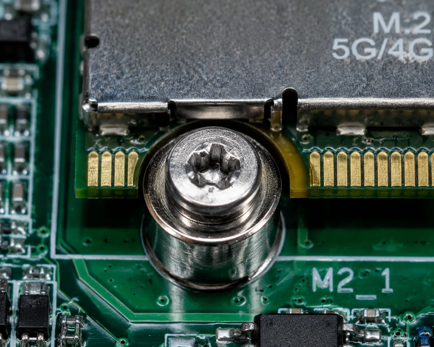 Locking screw securing Mini-PCIe module on PTZ camera board
How the Locking Mechanism Works
Both Mini-PCIe and M.2 use the same basic approach. The module slides into the edge connector at an angle — usually about 30 degrees. Then you press the module down flat. A metal standoff post on the PCB has a threaded hole. You drive a small Phillips-head screw through the hole at the end of the module into that standoff. The screw clamps the module firmly in place.
This is the same system used in millions of laptops, industrial PCs, and vehicle-mounted computers. It has been proven reliable under MIL-STD-810G9 vibration and shock testing. For a PTZ camera mounted on a highway pole or a moving vehicle, this level of mechanical security is more than enough.
What About Extreme Vibration?
Some of my clients mount PTZ cameras on trucks, trains, or even boats. These environments produce constant vibration at frequencies that can loosen screws over time. For these cases, I recommend two extra steps.
First, apply a small drop of medium-strength threadlocker (like Loctite 243) on the locking screw. This prevents the screw from backing out, but still allows removal with a standard screwdriver when you need to swap the module.
Second, some M.2 modules support an additional retention clip on the connector side. This clip snaps over the module edge and adds a second hold point. Between the screw, the threadlocker, and the clip, the module is not going anywhere.
Does Solder-Down Win on Vibration Resistance?
This is the one argument people make in favor of soldering. A soldered module has no connector that can work loose. That is true. But modern socket designs with locking screws close this gap almost completely. And the trade-off is terrible: you gain a small vibration margin, but you lose all the flexibility, repairability, and upgrade benefits I described above.
| Vibration Resistance Factor | Socket + Locking Screw | Solder-Down |
|---|---|---|
| Connector retention force | High (friction-fit + screw + optional clip) | N/A (no connector) |
| Resistance to constant vibration | Very good (with threadlocker) | Excellent |
| Resistance to shock/impact | Very good | Good (solder joints can crack under extreme shock) |
| Field replaceability after damage | Yes — swap in 10 minutes | No — full board replacement |
| Risk of solder joint fatigue over years | None (no solder on module) | Yes — thermal cycling can crack BGA joints |
Notice that last row. Solder joints are not perfect either. Over years of thermal cycling — hot days, cold nights — BGA solder balls can develop micro-cracks. This is a well-known failure mode in automotive and outdoor electronics. A socket connector does not have this problem. The gold-plated edge contacts maintain reliable connection through millions of thermal cycles.
For our Loyalty-Secu cameras, every unit goes through a 48-hour automated aging test before shipping. This test includes thermal cycling and simulated vibration. We have shipped over 50,000 socket-based PTZ cameras worldwide. The module retention failure rate is effectively zero.
Conclusion
Choose Mini-PCIe or M.2 sockets over soldering. You get faster upgrades, cheaper field repairs, better thermal performance, and one universal mainboard for every market.
1. Mini-PCIe is a standard interface for connecting expansion modules, commonly used in industrial and embedded systems. ↩︎ 2. M.2 is a compact, high-speed expansion standard supporting PCIe, SATA, and USB, ideal for cellular modules and SSDs. ↩︎ 3. 4G LTE modules provide cellular connectivity for IoT and security cameras; standards like Cat.4 define data speeds. ↩︎ 4. 5G NR offers faster speeds and lower latency than 4G, enabling higher data throughput for remote video surveillance. ↩︎ 5. LTE Category 4 supports up to 150 Mbps downlink, common in older 4G modules. ↩︎ 6. M.2 B-Key is a keying variant that supports USB, PCIe x2, and SATA interfaces, common for cellular modules. ↩︎ 7. H.265 (HEVC) compresses 4K video efficiently, reducing bandwidth requirements for cellular upload. ↩︎ 8. TVS diodes protect circuits from voltage spikes caused by lightning or surges, clamping excess voltage. ↩︎ 9. MIL-STD-810G defines environmental test methods for military equipment, including vibration and shock. ↩︎