
I have seen too many PTZ cameras fail at night. The IR LEDs wash out close targets. The laser blinds the center. The real problem? Bad switching logic between the two.
The IR LED + Laser dual illumination system switches based on zoom level, scene brightness, and safety rules. At wide angle, only IR LEDs activate. As the lens zooms in, the system gradually reduces LED power and increases laser output. At full telephoto, the laser takes over completely. Smart firmware adds hysteresis buffers and image-based feedback to keep the transition smooth and flicker-free.
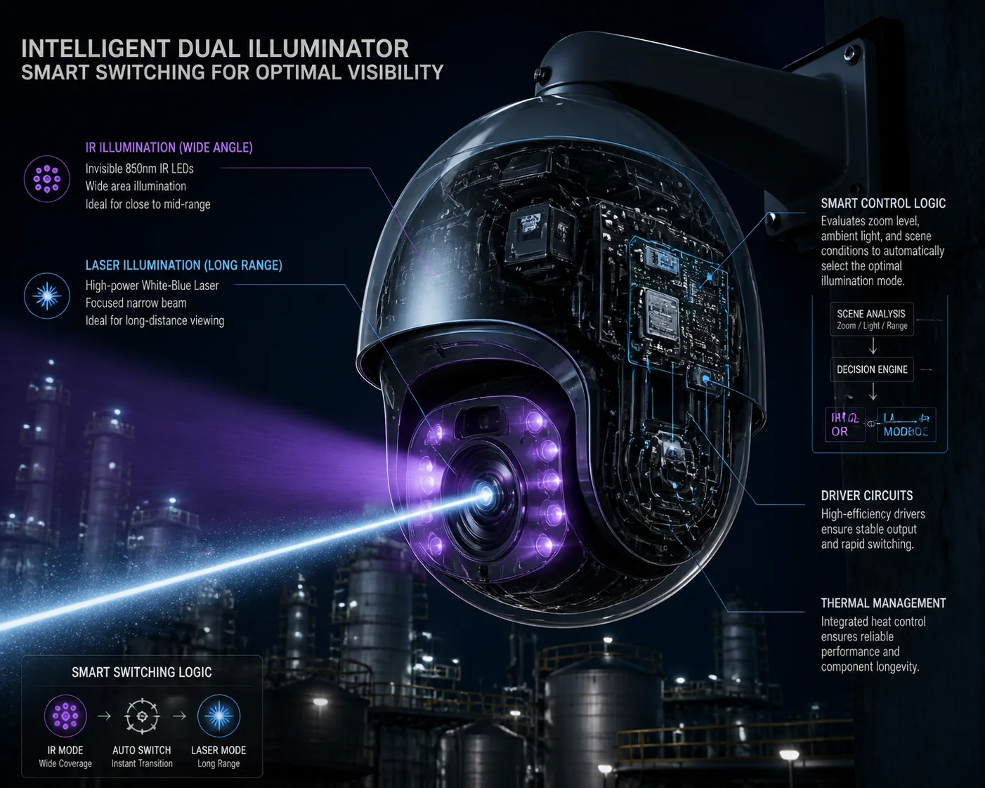 IR LED and Laser dual illumination PTZ camera switching logic
I will break down each part of this switching logic below. You will learn the exact zoom thresholds, whether you can run both systems at once, how to prevent flicker, and what settings you can adjust through the web interface. If you are sourcing PTZ cameras from China for long-range night vision projects, this is the technical detail that separates a $200 toy from a $2,000 tool.
Table of Contents
At What Zoom Level Does the Camera Transition From IR LEDs to the Laser Module?
I used to think the switch happened at one fixed point. It does not. The transition is a gradual curve, not a hard cutoff. And if your supplier tells you otherwise, that is a red flag.
In most professional dual-illumination PTZ cameras, the transition starts around 8x–12x optical zoom. Below that range, only IR LEDs are active. Between 8x and 20x, both systems overlap with shifting power ratios. Above 20x, the laser becomes the primary light source and LEDs drop to minimal or zero output.
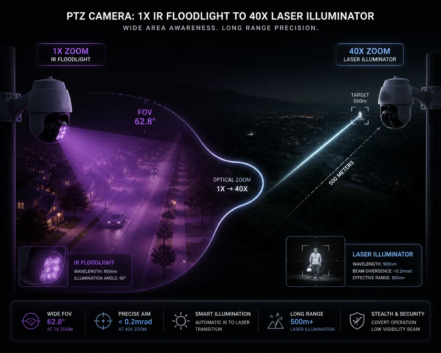 PTZ camera zoom level and IR laser transition point
The exact zoom threshold depends on your camera’s lens and the firmware configuration. But the underlying principle is always the same: match the illumination angle to the lens field of view (FOV). This is known as zoom tracking 6 in optical engineering.
Why IR LEDs Work Better at Wide Angle
IR LEDs have a wide beam spread. Most arrays cover 30° to 60°. This matches the field of view when your lens is at 1x to 8x zoom. The light spreads evenly across the scene. Targets at 20–80 meters get good, uniform illumination.
If you turn on the laser at this zoom level, you create a bright hot spot in the center. The edges of the frame stay dark. Close targets get overexposed. The image becomes unusable for identification.
Why Laser Takes Over at High Zoom
At 20x or 30x zoom, your lens FOV narrows to just 2°–3°. IR LEDs cannot focus their energy into such a small angle. Their light has already scattered and lost intensity at 200+ meters.
A laser module can project a tight beam — sometimes as narrow as 0.5°. This concentrated energy reaches 300m, 500m, even 1km. And in a well-designed system (like ZLID — Zoom Laser IR Diode), the laser beam angle adjusts in sync with the lens. When the lens zooms to 2°, the laser also narrows to about 2°.
The Overlap Zone: Where Both Work Together
The middle range (roughly 8x to 20x) is where things get interesting. Here, the firmware runs both LED and laser at partial power. The LED provides a soft base layer of light. The laser adds a focused boost in the center.
| Zoom Range | IR LED Power | Laser Power | Primary Use |
|---|---|---|---|
| 1x – 8x | 80% – 100% | OFF | Near-field, wide coverage |
| 8x – 12x | 50% – 80% | 10% – 30% | Mid-range transition |
| 12x – 20x | 20% – 50% | 30% – 70% | Mid-to-far bridging |
| 20x – 40x | 0% – 20% | 70% – 100% | Long-range surveillance |
This overlap zone is critical. If your camera jumps straight from LED to laser with no blending, you will see a sudden brightness shift in recorded footage. That is unacceptable for forensic-grade evidence. This gradual blending is known as cross-fade 7 in lighting control systems.
At Loyalty-Secu, we configure this curve during firmware development. We map the lens focal length to specific LED and laser power levels. Then we test in complete darkness from 10 meters to 500 meters. Every zoom position must produce a usable image — no white-out, no black holes, no flicker.
Can I Force Both Systems to Work Simultaneously for Maximum Mid-Range Brightness?
I get this question from system integrators almost every week. The short answer is yes, but you probably should not do it without understanding the trade-offs.
Yes, most professional PTZ cameras allow you to manually enable both IR LEDs and the laser at the same time. However, running both at full power creates problems — center overexposure, uneven lighting, and increased power draw. The best approach is to use the camera’s “Smart IR” or “Mixed Mode” setting, which automatically balances both sources based on the image feedback.
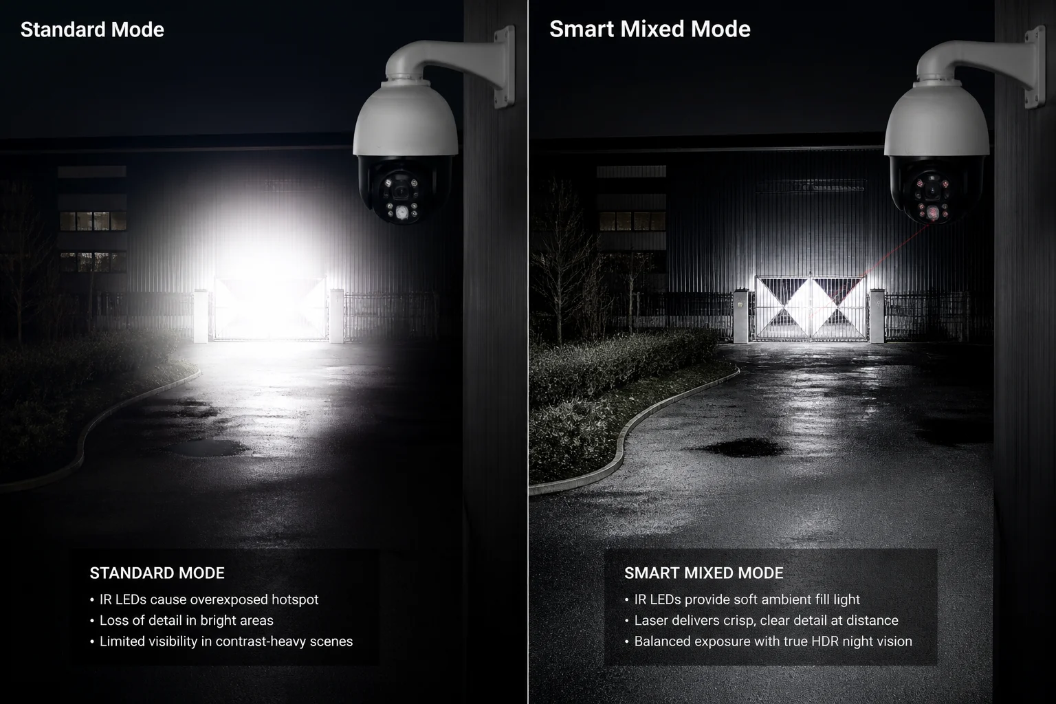 Dual IR LED and laser illumination working together on PTZ camera
Let me explain why “more light” does not always mean “better image.”
The Overexposure Problem
When you force both LED and laser to run at 100%, the center of the frame gets hit twice. The LED provides a wide wash. The laser adds a focused beam on top. The result? The center becomes a white blob. The camera’s AGC (Automatic Gain Control) tries to compensate by darkening the entire frame. Now your edges are too dark and your center is still too bright.
This is especially bad at mid-range distances (50–150 meters). The target is close enough for the LED to illuminate but also within the laser’s effective range. Double illumination creates double trouble.
When Simultaneous Mode Actually Helps
There are specific scenarios where running both makes sense:
- Fog or heavy rain: Water particles scatter IR light. Having both LED and laser increases the chance that some photons reach the target and bounce back. The laser’s higher coherence helps cut through moisture.
- Very dark environments with mixed distances: If you need to monitor a 100-meter perimeter and also watch a gate at 300 meters, a mixed mode can cover both zones at once — LED for the near field, laser for the far target.
- Testing and commissioning: During installation, running both systems helps you verify alignment and coverage before setting the automatic profile.
Recommended Operating Modes
| Mode | LED State | Laser State | Best For |
|---|---|---|---|
| Auto (Default) | Zoom-linked | Zoom-linked | General surveillance |
| LED Only | ON (Smart IR) | OFF | Warehouses, indoor, short range |
| Laser Only | OFF | ON (power adjustable) | 300m+ long-range targets |
| Mixed / Manual | ON (fixed %) | ON (fixed %) | Fog, rain, dual-distance scenes |
| Stealth / Starlight | OFF | OFF | Covert monitoring, ultra-low power |
For most projects, I recommend leaving the camera in Auto mode. The firmware handles the balance better than manual overrides in 90% of cases. But if you are working in a harsh environment — coastal fog, desert dust, heavy rain — ask your supplier if they support a “Fog Penetration” or “Force Mixed” mode. We build this into our firmware as a selectable option.
How Does the System Prevent a “Flicker” During the Transition Between IR and Laser?
This is the problem that keeps project managers awake at night. You install 50 cameras. They work fine in daylight. Then at night, every time a camera zooms, the footage flickers like a broken light bulb. Your client calls. Your reputation takes a hit.
The system prevents flicker by using a hysteresis buffer around the switching threshold. Instead of switching LED and laser at the same zoom point (for example, 10x), the firmware uses two separate thresholds — laser activates at 12x on zoom-in, but only deactivates at 8x on zoom-out. This 4x buffer zone eliminates the rapid on/off cycling that causes visible flicker in recorded video.
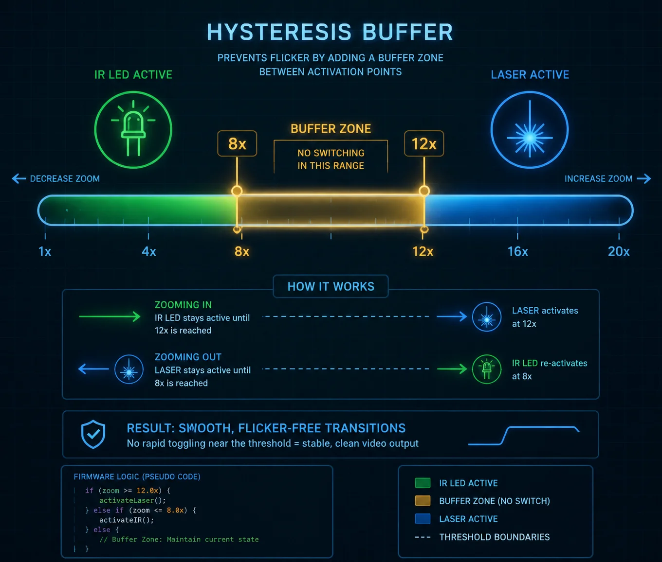 Hysteresis buffer preventing flicker in IR LED laser switching
Flicker is not just annoying. It corrupts evidence. It triggers false motion alerts. It makes your NVR storage fill up with useless clips. Here is how good firmware solves it.
What Causes the Flicker in the First Place
Imagine the switching threshold is set at exactly 10x zoom. The camera is on a preset tour. It zooms to 10x. The laser turns on. The image gets brighter. The auto-exposure adjusts. The image shifts. The camera’s auto-focus hunts slightly. The zoom motor adjusts by a fraction. Now the zoom reads 9.8x. The laser turns off. The image drops in brightness. The exposure adjusts again. The zoom motor corrects. Now it reads 10.1x. The laser turns back on.
This loop repeats several times per second. Each cycle creates a visible brightness jump. On a 30fps video stream, this looks like rapid flashing. That is flicker.
How Hysteresis Solves It
Hysteresis 1 is a simple engineering concept. It means using two different thresholds — one for going up, one for going down.
- Zoom in past 12x: Laser activates.
- Zoom out past 8x: Laser deactivates.
- Between 8x and 12x: The system keeps whatever state it was already in.
This creates a dead zone where no switching happens. The camera can zoom back and forth within this buffer without triggering any change. The result? Smooth, stable footage. This is also known as a Schmitt trigger 8 in electronics design.
The Role of Power Ramping
Good firmware also uses gradual power ramping instead of instant on/off. When the laser activates at 12x, it does not jump to 50% power immediately. It ramps up over 1–2 seconds:
- Frame 1: Laser at 5%
- Frame 10: Laser at 15%
- Frame 30: Laser at 30%
- Frame 60: Laser at target power
This slow fade-in is invisible to the human eye. It also gives the camera’s auto-exposure algorithm time to adjust gradually, instead of reacting to a sudden brightness spike.
What to Ask Your Supplier
When you evaluate a PTZ camera for dual illumination, ask these questions:
- “What is the hysteresis range for the LED-to-laser transition?”
- “Does the laser ramp up gradually or switch on instantly?”
- “Can I adjust the hysteresis buffer width through the web interface?”
If the supplier cannot answer these questions, the camera probably uses a simple hard switch. That means flicker. And flicker means callbacks from your clients.
At Loyalty-Secu, we set the default hysteresis buffer at 4x zoom steps. For custom OEM projects, we can adjust this value in firmware based on the specific lens and use case.
Is the Light Switching Threshold Adjustable via the Camera’s Web Interface?
I have worked with integrators who wanted full control over every parameter. I have also worked with installers who just wanted a camera that works out of the box. The answer needs to serve both.
Yes, on professional-grade PTZ cameras, the light switching threshold is adjustable through the web interface. You can typically set the zoom point where the laser activates, the power levels for each illumination source, the hysteresis range, and the operating mode (Auto, LED Only, Laser Only, or Mixed). Some cameras also expose these settings through ONVIF 2 or SDK for integration with third-party VMS platforms.
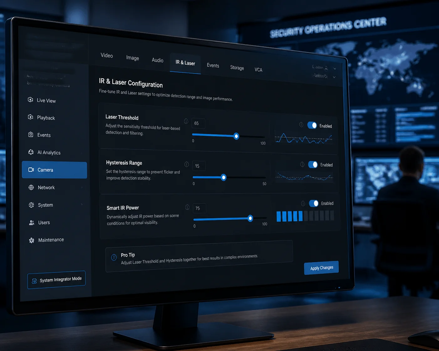 PTZ camera web interface IR LED laser switching settings
But not all web interfaces are created equal. Some give you a single “IR Mode: Auto/Off” toggle. Others give you full curve control. Here is what to expect at different price levels.
Basic Interface (Budget Cameras)
On lower-cost cameras, you may only see:
- IR Mode: Auto / Manual / Off
- IR Brightness: Low / Medium / High
That is it. No separate control for LED and laser. No threshold adjustment. No hysteresis settings. The firmware decides everything internally, and you cannot override it.
This works fine for simple installations. But if you need to fine-tune the behavior for a specific site — say a prison perimeter where the laser must never activate below 20x because of eye safety regulations — you are stuck.
Advanced Interface (Professional Cameras)
On professional PTZ cameras, the web interface should offer:
- Separate LED and Laser controls: Independent on/off and power adjustment for each source.
- Zoom threshold settings: You can define the zoom level where the laser begins to activate.
- Hysteresis buffer width: Adjustable dead zone to prevent flicker.
- Smart IR sensitivity: How aggressively the camera reduces LED/laser power when it detects overexposure.
- Mode presets: Auto, LED Only, Laser Only, Mixed, Stealth.
Integration With VMS and SDK
For large deployments, your integrators will not log into 200 cameras one by one. They need API access. The key protocols to check are:
| Feature | Protocol / Method | What It Controls |
|---|---|---|
| IR Mode switching | ONVIF Profile S | Basic on/off and auto mode |
| Laser power control | Manufacturer SDK | Fine-grained power % and threshold |
| Zoom-linked profiles | Custom CGI / API | Map zoom positions to light settings |
| Preset tour lighting | ONVIF + SDK | Different IR settings per preset position |
| Firmware update | HTTP / FTP | Push updated switching curves remotely |
At Loyalty-Secu, our cameras expose full IR and laser control through both the web interface and our SDK. For OEM customers, we can customize the interface layout and default values to match their brand and use case. If you need ONVIF-compatible laser control for integration with Milestone 3 or Blue Iris 4, we build that into the firmware from day one.
A Note on Safety Settings
One thing you should not be able to change freely is the safety logic. The minimum distance at which the laser activates should be locked in firmware, not exposed as a user-adjustable slider. If someone accidentally sets the laser to activate at 1x zoom, a person standing 5 meters from the camera could receive a concentrated IR beam to the eyes.
We lock our safety parameters behind an engineering-level password. Only authorized personnel can modify the laser activation distance and maximum power limits. This protects your end users and keeps your project compliant with IEC 60825-1 5. This is referred to as laser safety interlock 9 in safety engineering.
Conclusion
The IR LED + Laser switching logic comes down to three things: zoom position, scene brightness, and safety limits. Get these right in firmware, and your camera delivers clean footage from 10 meters to 1 kilometer — no flicker, no white-out, no blind spots. This kind of adaptive illumination 10 is what separates professional surveillance systems from consumer-grade equipment.
1. Hysteresis threshold control for flicker-free illumination switching. ↩︎ 2. ONVIF Profile S for PTZ IR and laser control. ↩︎ 3. Milestone VMS PTZ illumination API integration. ↩︎ 4. Blue Iris laser control via ONVIF commands. ↩︎ 5. IEC 60825-1 laser product safety classification. ↩︎ 6. Zoom tracking technology for zoom-laser synchronization. ↩︎ 7. Cross-fade lighting control for smooth illumination transitions. ↩︎ 8. Schmitt trigger hysteresis for switching threshold control. ↩︎ 9. Laser safety interlock mechanisms for PTZ cameras. ↩︎ 10. Adaptive illumination systems for surveillance applications. ↩︎