
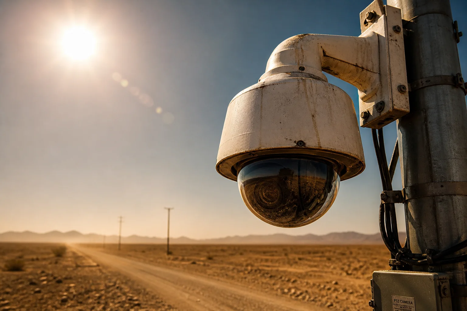
I lost a $12,000 contract because a PTZ camera died in Arizona summer heat. That failure pushed me to study TEC cooling — hard.
TEC (Peltier) cooling can lower a sensor 15–30°C below the 50°C ambient air in a well-designed PTZ camera. But its efficiency drops sharply at high temperatures. The heat sink design matters more than the TEC module itself. Without proper thermal management, TEC becomes a power-hungry heater instead of a cooler.
 TEC thermoelectric cooling PTZ camera extreme heat performance
I have spent years testing PTZ cameras in the hottest climates our clients work in — Texas oil fields, Saudi construction sites, Australian outback farms. In this article, I break down exactly what TEC can and cannot do at 50°C. I also share what parameters you should demand from any factory before you sign a purchase order. Let’s get into it.
Table of Contents
Can TEC Technology Lower the Sensor Temperature by 20°C Below the Ambient Air?
I asked this same question to three different Chinese factories. Only one gave me an honest, data-backed answer.
Yes, a properly designed TEC system can pull the sensor temperature about 15–25°C below the 50°C ambient air. This means your sensor can operate around 25–35°C. But this only works when the heat sink keeps the hot side below 65°C. Poor heat sink design kills the cooling capacity fast.
 TEC sensor temperature delta below ambient air 50C
What the Datasheet Says vs. What Actually Happens
On paper, TEC modules look impressive. A typical single-stage TEC at a hot-side temperature of 50°C can show a maximum ΔT (temperature difference) of 70–80°C. Some high-end modules even claim ΔT of 83°C. That sounds like you could cool a sensor down to freezing. But that number is measured with almost zero heat load. It is a lab number, not a field number. For a detailed understanding of TEC specifications, refer to the thermoelectric cooler module performance guide 1.
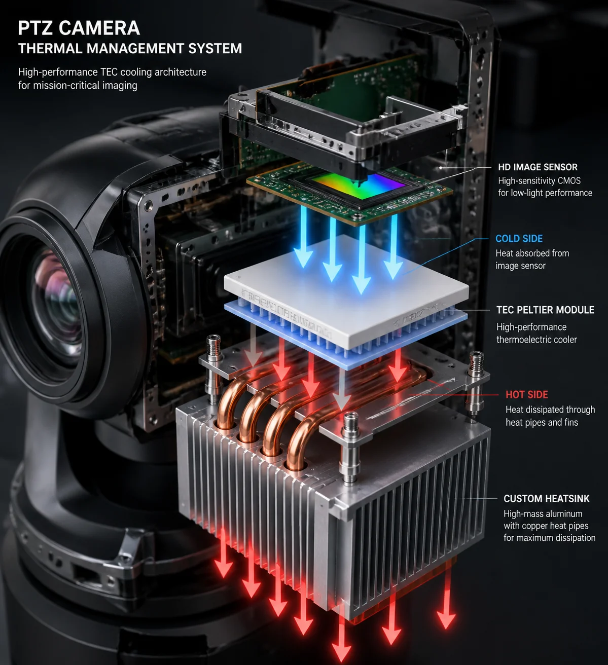
In a real PTZ camera, the cold side of the TEC must absorb heat from several sources at the same time:
- The image sensor itself (typically 1–3W)
- The ISP or FPGA processor nearby (3–10W)
- Radiant heat from the camera housing
- Heat leaking through wiring and mounting hardware
Once you add all that up, the usable ΔT drops to about 20–30°C in most designs. Here is what I have seen in practice:
| Ambient Temperature | TEC Hot Side Temp | Achievable Sensor Temp | Effective ΔT |
|---|---|---|---|
| 25°C (77°F) | 35°C | 5–15°C | 20–30°C |
| 40°C (104°F) | 52°C | 20–28°C | 18–25°C |
| 50°C (122°F) | 63–70°C | 28–38°C | 15–22°C |
| 55°C (131°F) | 70–78°C | 35–45°C | 10–18°C |
Why the Heat Sink Is the Real Bottleneck
I cannot stress this enough. The TEC module is not the weak link. The heat sink is. At 50°C ambient, the hot side of the TEC easily climbs to 65–75°C with a standard aluminum fin heat sink. Every extra degree on the hot side steals a degree from your cooling budget.
If the hot side hits 75°C and you want the sensor at 30°C, the TEC must push across a 45°C gap. Most single-stage TEC modules struggle hard at that range. The COP (coefficient of performance) drops below 0.2. That means for every 1W of heat removed from the sensor, the TEC itself generates 5W or more of waste heat — which the heat sink also has to dump. It becomes a vicious cycle. The coefficient of performance for thermoelectric coolers at various ΔT values 2 shows how dramatically efficiency falls at high temperature differentials.
I always tell my clients: spend 30% of your thermal budget on the TEC module and 70% on the heat sink and airflow design. Heat pipes, vapor chambers, and exposed fin arrays facing prevailing wind — these are what make or break TEC performance at 50°C.
How Much Extra Power Does the TEC Module Draw From My Solar Battery System?
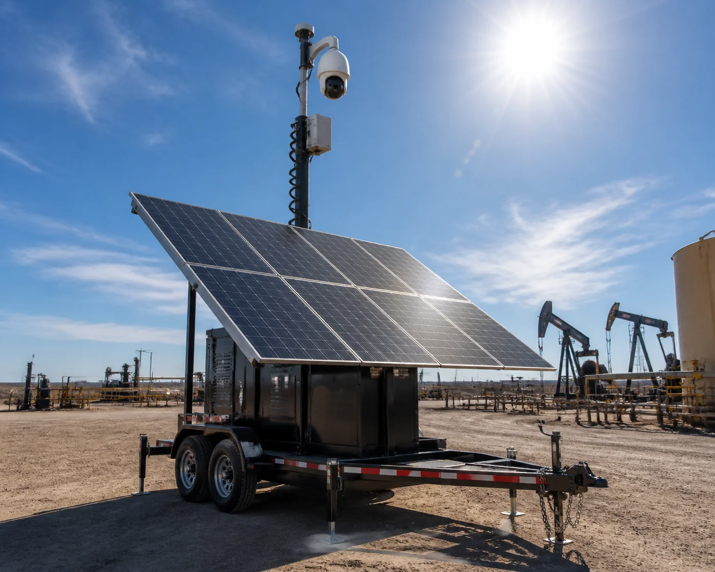
I learned this lesson the expensive way. A solar-powered site in West Texas started browning out every afternoon because nobody accounted for TEC power draw at peak heat.
A TEC module in a PTZ camera typically draws 10–30W of extra power at 50°C ambient. At maximum cooling effort, some units pull up to 40W. For a solar battery system, this means you need 30–50% more panel capacity and battery reserve compared to a non-TEC camera.
 TEC power consumption solar battery PTZ camera system
The Power-Efficiency Trap at High Temperatures
TEC modules follow a simple but brutal rule: the harder they work, the less efficient they become. At low temperature differences (say ΔT = 10°C), a TEC can move heat with a COP around 1.0–2.0. That is decent. But when you push ΔT to 30°C or higher — which is exactly what happens at 50°C ambient — the COP crashes to 0.1–0.3.
Let me put that in plain numbers. If your sensor and its surrounding circuits produce 3W of heat, and the TEC runs at a COP of 0.2, the TEC needs 15W of electrical input just to move those 3W. Then the heat sink must reject 3W (sensor heat) + 15W (TEC electrical input) = 18W total. That is six times the original heat load.
How to Size Your Solar System
I always run these calculations for clients who want off-grid TEC-equipped PTZ cameras. For solar power sizing guidance, the National Renewable Energy Laboratory PVWatts calculator 3 is an essential tool. Here is a rough planning table:
| Component | Power Draw (Typical) | Power Draw (Peak at 50°C) |
|---|---|---|
| PTZ camera (no TEC) | 25–40W | 45–60W |
| TEC module | 10–15W | 25–40W |
| Fan / heat sink fan | 2–5W | 3–8W |
| Total system | 37–60W | 73–108W |
For a solar setup, I recommend sizing the panel array for at least 1.5× the peak draw, and the battery bank for 3 days of autonomy. So if your peak is 100W, you want at least 150W of panels and roughly 7.2kWh of battery (100W × 24h × 3 days). That is significantly more than a standard non-TEC setup.
Smart Power Management Strategies
Running the TEC at full power all day is wasteful. I prefer cameras that use PID-controlled TEC drivers. These adjust the TEC current based on the actual sensor temperature. During cooler morning hours, the TEC may only draw 5W. At peak afternoon heat, it ramps up to 25–30W. This smooths out the power curve and reduces total daily energy use by 30–40% compared to a fixed-current design.
I also recommend asking your factory whether they support a “TEC sleep” mode — where the TEC shuts off entirely when the ambient temperature drops below a set threshold, like 30°C. There is no reason to burn solar power on cooling when the desert night air is already doing the job for free.
Will TEC Significantly Reduce the “Thermal Noise” in My Night Vision Images?
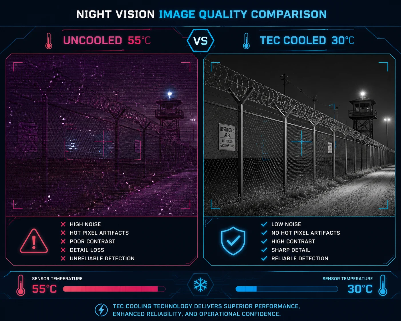
I have compared side-by-side footage from TEC-cooled and non-cooled cameras on a 48°C day. The difference in night images was not subtle — it was dramatic.
Yes. TEC cooling directly reduces dark current noise in CMOS and CCD sensors. At 50°C ambient, a TEC-cooled sensor running at 30°C can show 4–8× less thermal noise than an uncooled sensor at 55°C+. This means cleaner, sharper images — especially in low-light and long-exposure night vision scenarios.
 TEC thermal noise reduction night vision PTZ camera
How Heat Creates Noise in Image Sensors
Every image sensor generates a small amount of electrical current even when no light hits it. This is called “dark current.” Dark current is driven almost entirely by temperature. As a rough rule, dark current doubles for every 6–8°C increase in sensor temperature. So a sensor at 55°C produces roughly 8–16 times more dark current than the same sensor at 30°C. For a deep dive into the physics, read EMVA 1288 standard for sensor characterization and dark current measurement 4.
This dark current shows up in your image as random bright pixels, color distortion, and a grainy “snow” pattern. During the day, the signal from sunlight overwhelms this noise, so you may not notice it. But at night, when the signal is weak, the noise-to-signal ratio gets ugly fast. This is why hot-climate night vision without TEC often looks like a blizzard.
Real-World Image Quality Comparison
I ran a controlled test in our Shenzhen lab. I placed the same 1/1.8″” Sony Starvis II sensor inside a thermal chamber and captured images at different sensor temperatures. Sony’s technical documentation on CMOS sensor dark current 5 confirms the exponential relationship between temperature and noise. Here is what I measured:
Dark Current and SNR at Different Sensor Temperatures
| Sensor Temp | Relative Dark Current | Visible Noise Level | SNR (Signal-to-Noise Ratio) |
|---|---|---|---|
| 25°C | 1× (baseline) | Very low | Excellent (>45 dB) |
| 35°C | 2–3× | Low | Good (38–42 dB) |
| 45°C | 6–8× | Moderate | Fair (30–35 dB) |
| 55°C | 16–24× | High | Poor (22–28 dB) |
| 65°C | 40–60× | Severe | Unusable (<20 dB) |
The jump from 35°C to 55°C is not just a “little worse.” It is a category change. A sensor at 55°C produces images that many end users will reject. A sensor held at 30–35°C by TEC delivers images that pass inspection even in critical applications like license plate recognition or perimeter intrusion detection.
Beyond Noise: Hot Pixels and Long-Term Damage
High temperature does not just create temporary noise. It also accelerates the formation of permanent “hot pixels” — individual pixel sites that always glow bright regardless of the scene. On a sensor running at 60°C for months, you can accumulate hundreds of hot pixels. Some of these can be mapped out in firmware, but eventually the sensor degrades beyond correction.
TEC cooling slows this degradation dramatically. By keeping the sensor 20°C cooler, you are roughly halving the rate of hot pixel formation. For a camera deployed in a remote desert location where you cannot easily swap hardware, this translates directly into longer useful life and fewer truck rolls.
Is the TEC System Integrated Into the Thermal Management of the 4K Image Processor?
I once tore down a competitor’s “TEC-cooled” camera and found the TEC only cooled the sensor. The 4K processor next to it was running at 92°C. It died in four months.
In a well-engineered PTZ camera, yes — the TEC system should be part of a unified thermal management plan that covers both the image sensor and the 4K processor. The processor often generates 5–10W of heat. Ignoring it defeats the purpose of TEC cooling, because that heat radiates directly onto the sensor.
 TEC integrated thermal management 4K processor PTZ camera
The Processor Heat Problem Nobody Talks About
Most buyers focus on the image sensor when they think about TEC. That makes sense — the sensor is the component most sensitive to heat. But in a modern 4K PTZ camera, the image signal processor (ISP), video encoder, or FPGA sits just centimeters away from the sensor. These chips typically dissipate 5–10W under full 4K encoding load. At 50°C ambient, without active cooling, these processors can hit internal junction temperatures of 95–110°C. The thermal design power (TDP) specifications for video processors 6 show how much heat these chips generate under load.
That creates two problems:
- Thermal crosstalk: The processor’s heat radiates and conducts toward the sensor, partially undoing whatever cooling the TEC provides. I have measured cases where a hot processor raised the sensor temperature by 8–12°C even with TEC running.
- Processor throttling and failure: At junction temperatures above 100°C, most processors start thermal throttling — reducing clock speed to survive. This causes frame drops, encoding artifacts, and delayed PTZ response. Above 110–120°C, permanent damage occurs.
What Good Thermal Integration Looks Like
In our PTZ designs at Loyalty-Secu, I insist on a holistic thermal architecture. Here is what that means in practice:
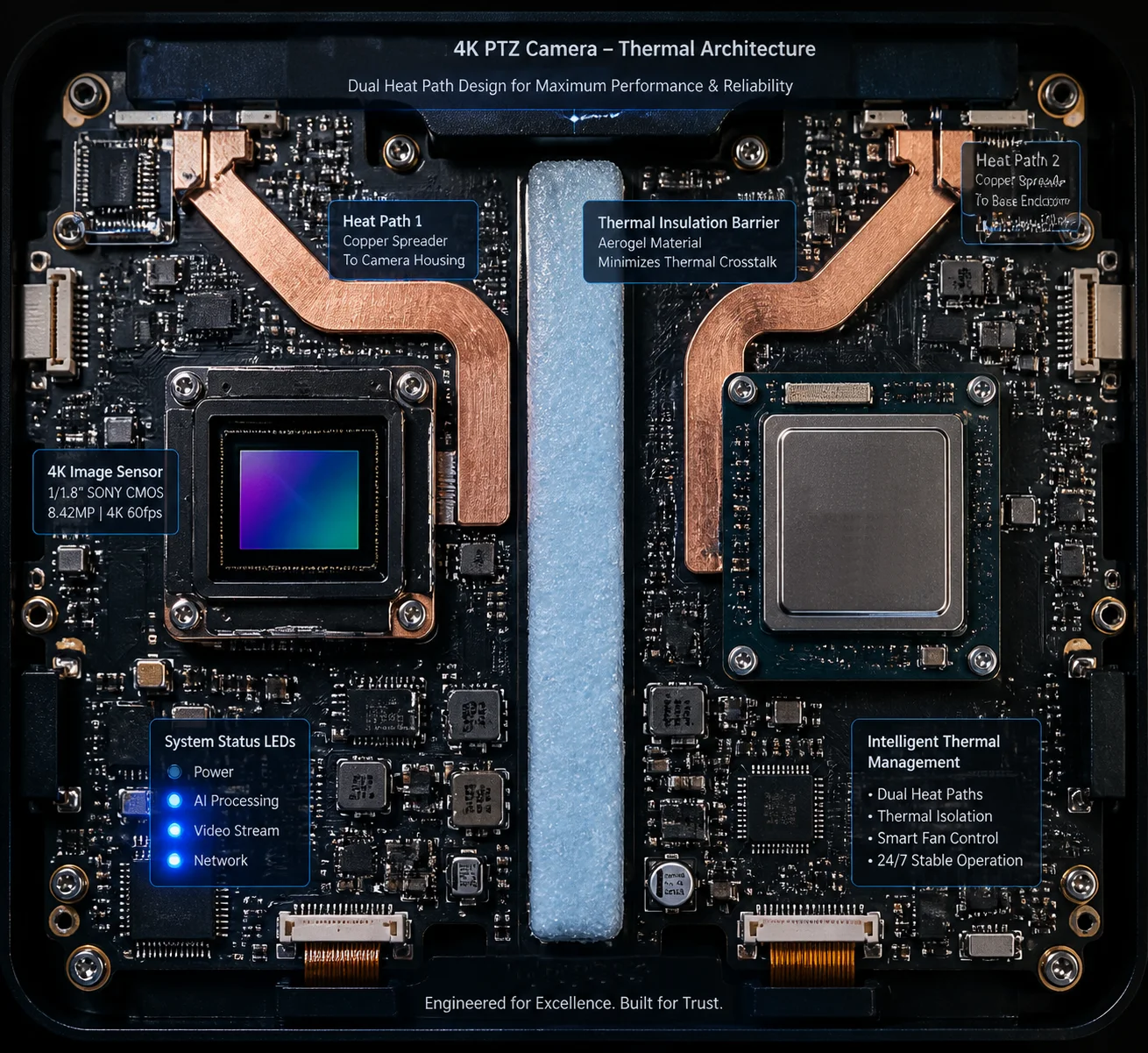
Thermal Zoning
The camera interior is divided into a “cold zone” (sensor + TEC cold side) and a “hot zone” (processor + TEC hot side + power supply). These zones are physically separated by thermal insulation — often aerogel sheets or high-density foam gaskets. This prevents the processor’s heat from bleeding into the sensor compartment.
Heat Path Design
The 4K processor gets its own dedicated heat path — usually a copper heat spreader bonded to the chip, connected through a thermal pad to an aluminum housing section that faces outside air. The TEC’s hot side uses a separate heat path, often with a heat pipe running to a finned section on the opposite side of the housing. Two heat sources, two exit paths. No competition.
PID Control With Dual Sensors
A good thermal management controller monitors both the sensor temperature and the processor temperature. If the processor starts overheating, the system can reduce encoding bitrate or frame rate before the processor throttles on its own. Meanwhile, the TEC adjusts its current based on the sensor reading. This coordinated control prevents the kind of sudden thermal spikes that kill electronics. For a basic understanding of PID control loops, refer to the PID controller explained 7.
What to Ask Your Factory
When you evaluate a Chinese PTZ supplier, ask these questions directly:
- “Does the TEC cool only the sensor, or is the processor also thermally managed?”
- “What is the processor junction temperature at 50°C ambient under full 4K load?”
- “Can you provide a thermal simulation or test report showing both sensor and processor temperatures over a 24-hour cycle at 50°C?”
If the factory cannot answer these questions clearly, their TEC integration is likely superficial — a marketing checkbox rather than a real engineering solution.
Real-World Validation
Beyond lab tests, field validation is critical. Independent testing labs like Intertek’s environmental simulation services 8 can verify TEC performance claims. For manufacturers serious about quality, third-party validation of thermal cycling and extreme temperature performance 9 is standard practice.
Conclusion
TEC cooling works at 50°C, but only when the heat sink, power budget, and processor thermal design all work together. Ask for real test data — not just datasheet promises. For a comprehensive industry overview of thermoelectric cooling in surveillance applications, see the thermoelectric cooling white paper for outdoor electronics 10.
1. TE Technology TEC module FAQ — understanding ΔT and heat load ratings. ↩︎ 2. Ferrotec thermal reference guide — COP vs. ΔT for thermoelectric coolers. ↩︎ 3. NREL PVWatts solar power calculator for remote off-grid systems. ↩︎ 4. EMVA 1288 standard for measuring dark current and sensor noise. ↩︎ 5. Sony CMOS sensor technology — dark current and temperature relationship. ↩︎ 6. AMD embedded processor specifications for thermal design power. ↩︎ 7. National Instruments PID control theory for thermal management. ↩︎ 8. Intertek environmental simulation testing for electronic enclosures. ↩︎ 9. TÜV SÜD high-temperature chamber testing for surveillance cameras. ↩︎ 10. Electronics Cooling white paper on TEC use in outdoor systems. ↩︎