
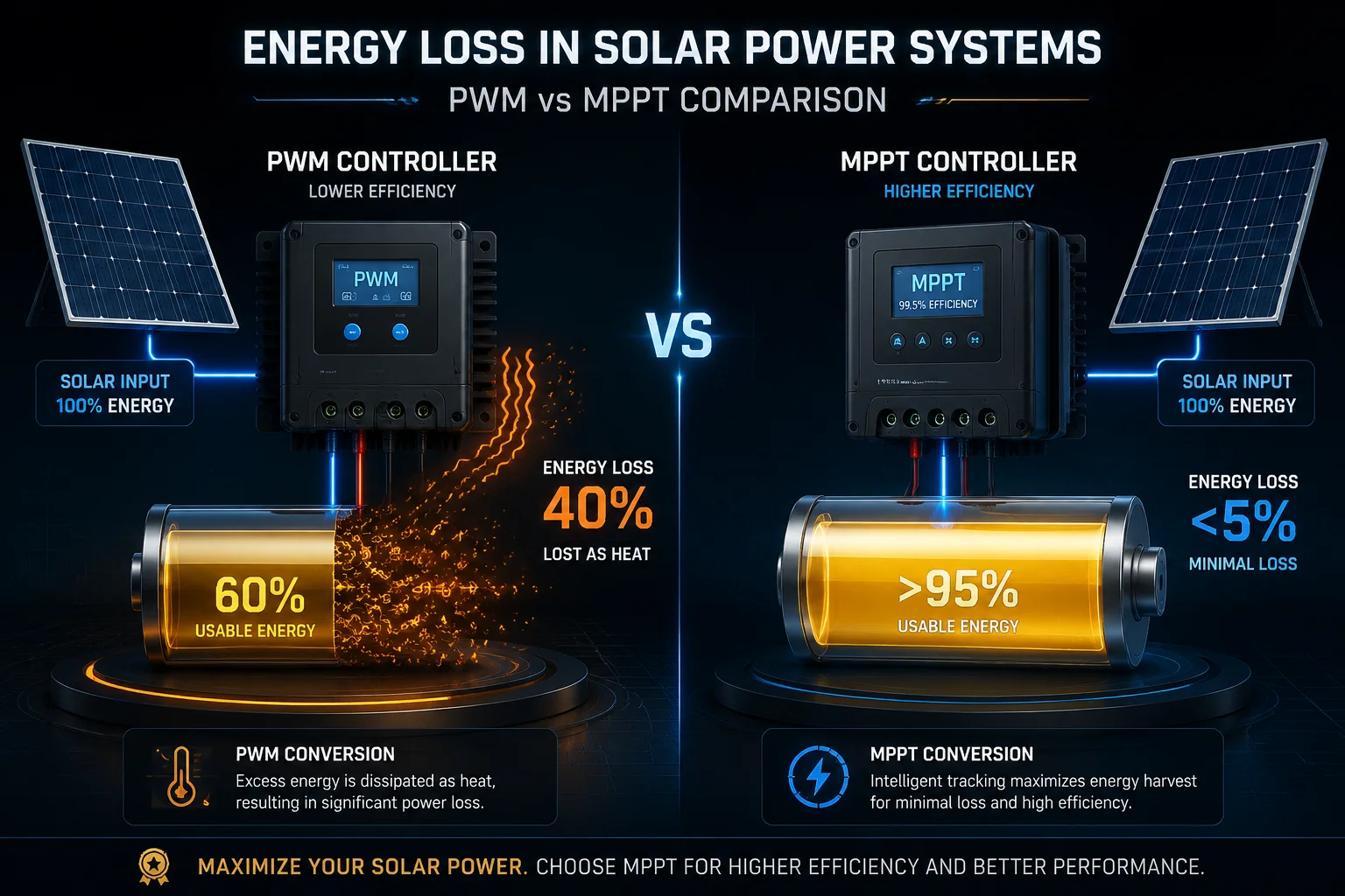
I lost 40% of my solar power before it even reached the battery. That single mistake nearly killed my off-grid monitoring project.
The peak conversion loss depends on your charge controller type. A PWM controller1 wastes 30% to 45% of panel energy as heat because it clips voltage down. An MPPT controller converts voltage efficiently, losing only 2% to 5% through its DC-DC buck conversion circuit.
 solar panel voltage conversion loss to battery
Below, I break down exactly where this energy disappears, why it matters for your 4G solar surveillance system, and how to pick the right controller to keep your site online 24/7.
Table of Contents
Is the DC-to-DC Conversion Efficiency Optimized for the Specific Voltage of a 12V System?
I assumed any controller would work fine with a 12V battery. That assumption cost me weeks of undercharged batteries and random system shutdowns.
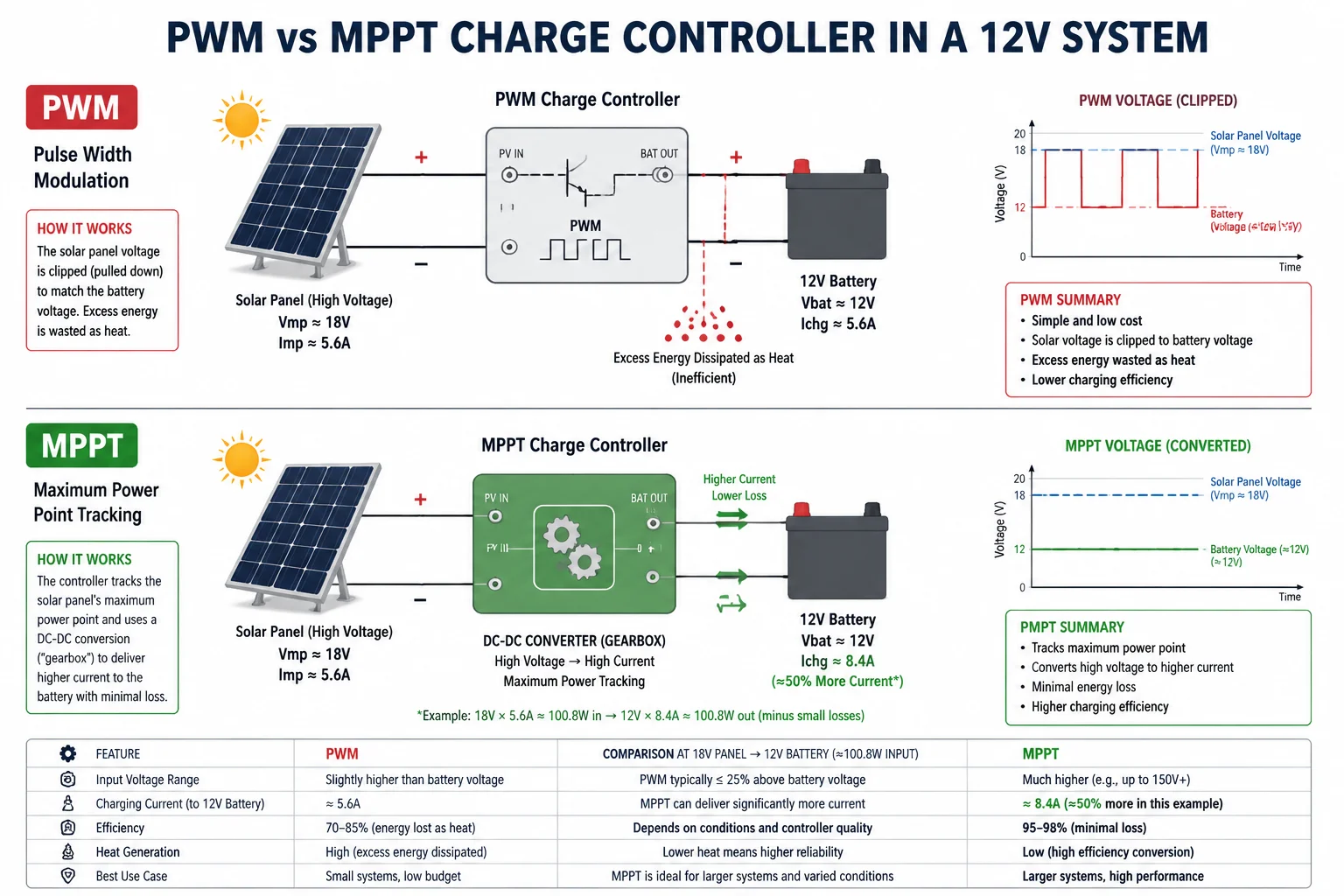
No, not all controllers optimize DC-to-DC conversion for 12V systems. PWM controllers simply clip the panel voltage to match battery voltage, wasting the difference. Only MPPT controllers perform true DC-to-DC buck conversion, matching the panel’s maximum power point to the 12V battery’s needs with 95% to 98% efficiency.
 DC to DC conversion efficiency 12V solar system
How PWM Handles a 12V System
A PWM controller does not convert voltage. It acts like a fast on-off switch. When your solar panel outputs 18V at its peak power point, the PWM controller pulls that voltage down to whatever the battery sits at — usually 12V to 14.4V.
The problem is simple math. Your panel produces 18V × 5.5A = 99W at its best. But the PWM forces the panel to operate at 12V × 5.5A = 66W. That missing 33W turns into nothing useful. It just vanishes.
How MPPT Handles a 12V System
An MPPT controller is a true DC-to-DC converter. It lets the panel run at 18V where it produces the most power. Then it steps that voltage down to 12V-14.4V while boosting the current. Think of it like a gear box in a car. You trade speed for torque.
So instead of 5.5A going into your battery, you might get 6.5A or more. The panel still outputs its full 99W, and after a small 3-5% internal loss, about 94-97W reaches your battery.
Why This Matters More in Cold Weather
Here is something most people miss. Solar panels produce higher voltage in cold weather. On a winter morning, your 18V panel might output 21V or even 22V. For a PWM controller, this makes the gap worse. The loss jumps from 33% to over 45%.
For an MPPT controller, cold weather is actually a bonus. More voltage means more energy to convert into current. Your battery charges faster on cold sunny days with MPPT.
| Condition | Panel Voltage | PWM Loss | MPPT Loss |
|---|---|---|---|
| Summer (hot panel) | 16V | ~15% | ~3% |
| Normal (25°C) | 18V | ~33% | ~4% |
| Winter (cold panel) | 21V | ~43% | ~4% |
The Real-World Impact on a 4G Surveillance System
For David’s typical project — a 120W panel feeding a 40AH battery that powers a 4G PTZ camera2 — this efficiency gap is not academic. It decides whether the camera stays online during three cloudy days in a row.
With PWM, your 120W panel delivers roughly 72W in normal conditions. With MPPT, it delivers about 114W. That 42W difference, multiplied over 5-6 hours of usable sunlight, means 210Wh more energy per day. That is the difference between a full battery and a dead camera at 3 AM.
How Much Energy Is Lost as Heat Inside the Controller During a High-Current Charge?
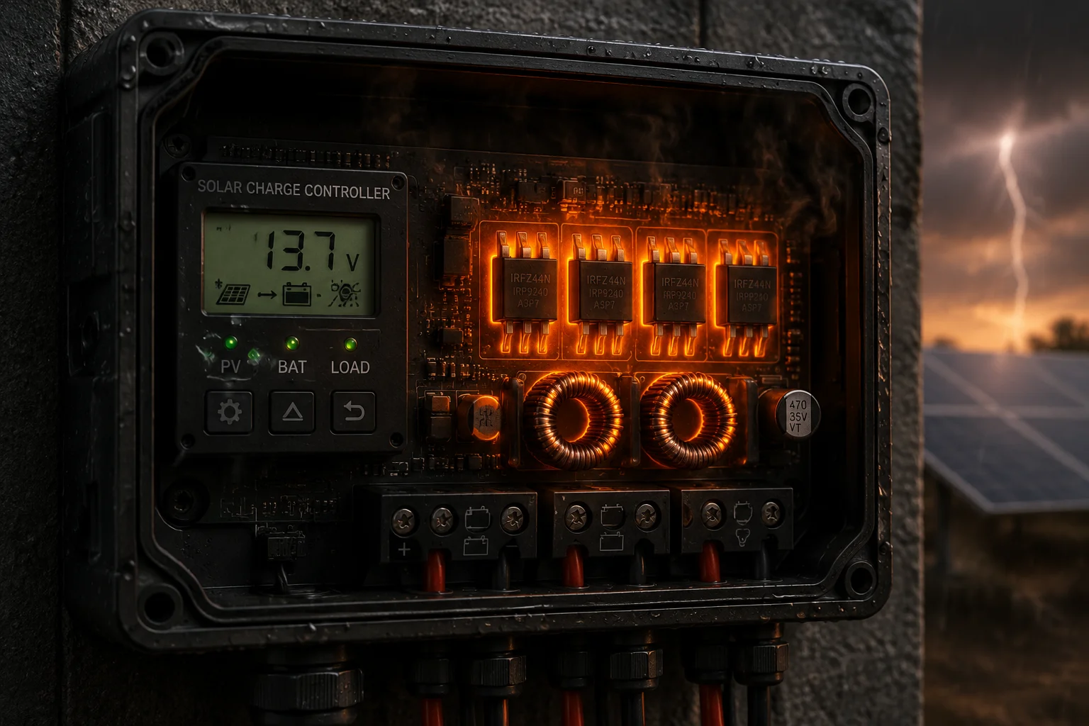
I once touched a charge controller during peak charging. It was hot enough to burn my finger. That heat is your electricity disappearing.
During high-current charging, a typical MPPT controller converts 2% to 5% of total power into heat. For a 100W system, that means 2W to 5W of continuous heat generation inside the controller enclosure. A PWM controller generates less internal heat itself, but wastes far more energy by forcing the panel to operate inefficiently.
 heat loss inside solar charge controller high current
The Three Heat Sources Inside an MPPT Controller
Even the best MPPT controller cannot escape physics. Three components generate heat during conversion:
1. MOSFET Switching Losses
The power MOSFETs inside the controller switch on and off thousands of times per second. Each switch creates a tiny moment where the transistor is neither fully on nor fully off. During that moment, it acts like a resistor and generates heat. Higher switching frequency means more of these moments per second.
2. Inductor DCR (DC Resistance) Losses
The inductor is the heart of the DC-DC converter. It stores energy in its magnetic field and releases it at the lower voltage. But the copper wire inside the inductor has resistance. Current flowing through this resistance creates heat. The formula is simple: Heat = I² × R. Double the current, and you get four times the heat.
3. Conduction Losses in PCB Traces and Terminals
Every wire, solder joint, and copper trace on the circuit board has some resistance. At high currents (8A-10A for a 120W/12V system), even tiny resistances add up.
Heat Generation at Different Power Levels
| Charging Power | MPPT Internal Heat (at 96% efficiency) | PWM Internal Heat | Total System Waste (PWM) |
|---|---|---|---|
| 50W | 2W | 1W | ~17W (voltage clipping) |
| 100W | 4W | 1.5W | ~33W (voltage clipping) |
| 150W | 6W | 2W | ~50W (voltage clipping) |
Notice something important. The PWM controller itself runs cooler because it does less work internally. But the total wasted energy is much higher — it just happens at the panel side, not inside the box.
Why Heat Matters in Sealed Enclosures
For off-grid 4G surveillance, the charge controller usually sits inside a sealed weatherproof box on the pole. There is no fan. There is no airflow. That 4-6W of heat has nowhere to go.
When the controller’s internal temperature rises above its rated limit (usually 45°C to 55°C), it starts to throttle. It reduces charging current to protect itself. This creates a secondary loss on top of the conversion loss.
I have seen systems in the Middle East where the controller throttles for 3-4 hours during midday — exactly when solar production peaks. The system misses its best charging window because of trapped heat.
Practical Solutions
Good thermal design matters as much as controller efficiency. Use aluminum-backed enclosures that conduct heat outward. Mount the controller on the shaded side of the box. Leave at least 20mm of air gap around the controller. These simple steps keep the controller below its throttle point and protect your full charging capacity.
Does the Peak Loss Increase as the Battery Reaches the “Absorption” or “Float” Stage?
I noticed my system charged fast in the morning but seemed to waste more energy in the afternoon. The battery was nearly full, but the panel was still producing. Where did that power go?
Yes, peak conversion loss increases during Absorption and Float stages. As the battery voltage rises closer to the panel voltage, the MPPT converter operates in a narrower range. More importantly, the controller intentionally reduces current during these stages, which means available solar energy is deliberately curtailed — not converted.
 battery absorption float stage conversion loss solar
Understanding the Three Charging Stages
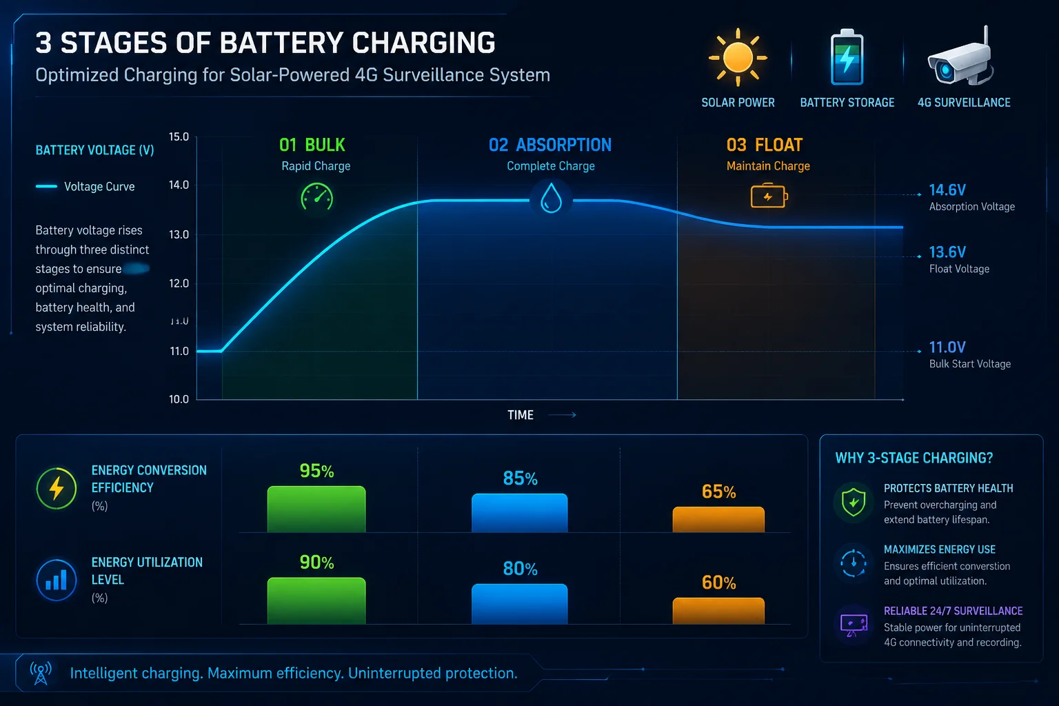
A proper charge controller moves through three stages: Bulk, Absorption, and Float. Each stage has different loss characteristics.
Bulk Stage (0% to ~80% SOC): The controller pushes maximum current into the battery. The battery voltage is low (11.5V-13V), so the voltage gap between panel and battery is large. MPPT works at peak efficiency here because it has plenty of room to convert voltage into current. This is where you get the most useful energy transfer.
Absorption Stage (~80% to ~95% SOC): The controller holds voltage constant at 14.4V (for a 12V lead-acid battery3) and lets current taper naturally. As the battery fills up, it accepts less current. The controller must now waste or redirect the excess energy the panel still produces.
Float Stage (~95% to 100% SOC): The controller drops voltage to 13.6V and only trickles in enough current to maintain full charge. Most of the panel’s output is simply not used.
Where the “Loss” Actually Goes
During Absorption and Float, the loss is not purely a conversion efficiency problem. It is a deliberate curtailment. The controller tells the panel to move away from its maximum power point. It shifts the operating point to produce only what the battery can accept.
This is not wasted in the traditional sense — the panel simply produces less. But from a system perspective, you are capturing less of the available solar energy.
The Real Efficiency Numbers by Stage
| Charging Stage | Battery Voltage | Current Accepted | Conversion Efficiency | Energy Utilization |
|---|---|---|---|---|
| Bulk | 11.5V – 13.0V | Maximum (6-8A) | 96-98% | 95%+ |
| Absorption | 14.4V (held) | Tapering (4A → 1A) | 94-96% | 50-70% |
| Float | 13.6V (held) | Trickle (0.2-0.5A) | 90-93% | 10-20% |
The conversion efficiency itself drops slightly during Float because the controller operates at very low power. DC-DC converters are less efficient at light loads — the fixed switching losses become a larger percentage of the tiny power being transferred.
What This Means for Your 4G Camera System
For a 4G PTZ camera drawing 15-25W continuously, the battery rarely sits at Float during winter months. The load keeps pulling energy out, so the controller stays in Bulk or early Absorption most of the day. This is actually good — it means your system operates in the highest-efficiency zone.
But in summer, when days are long and the camera draws less power (no heater needed), the battery fills up by noon. The system then sits in Float for 4-5 hours, and your 120W panel produces maybe 10W of useful energy during that time. This is not a problem for system health, but it means your panel is oversized for summer — which is exactly what you want, because you sized it for the worst winter day.
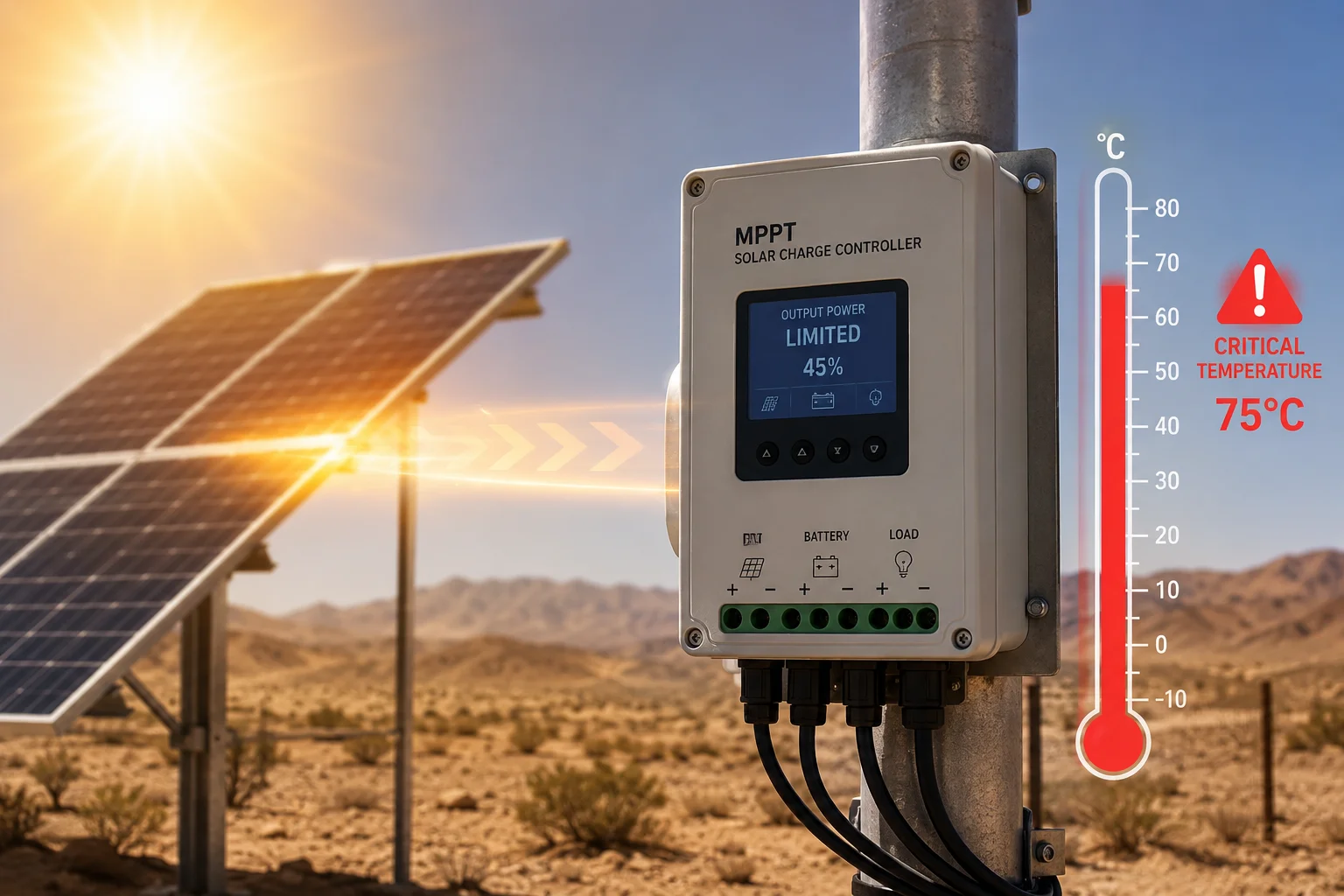
What Is the Maximum Wattage the Controller Can Handle Without Triggering Thermal Throttling?
I pushed a 20A controller with a 300W panel array once. It worked for an hour, then quietly cut its own output in half. No alarm. No warning. Just half the charging speed when I needed it most.
Most MPPT controllers begin thermal throttling4 when internal temperature exceeds 45°C to 55°C. A 20A/12V controller rated for 260W will typically throttle at 200-220W in a sealed enclosure at 35°C ambient temperature. The maximum wattage before throttling depends on ambient temperature, enclosure airflow, and mounting method — not just the controller’s nameplate rating.
 maximum wattage solar controller thermal throttling limit
Nameplate Rating vs. Real-World Capacity
Every charge controller has a rated maximum. A “20A MPPT controller” for a 12V system is rated for 20A × 14.4V = 288W maximum output. But this rating assumes 25°C ambient temperature and open-air mounting.
In the real world, your controller sits inside a sealed IP65 box on a pole in Texas summer heat. The ambient inside that box can reach 50°C or higher. At that temperature, the controller might only deliver 60-70% of its rated capacity before throttling kicks in.
How Thermal Throttling Works
The controller has a temperature sensor on its main MOSFET or heatsink. When temperature crosses the threshold, the firmware reduces the PWM duty cycle. This lowers the charging current, which reduces heat generation. The controller protects itself, but your battery pays the price.
The dangerous part is that most controllers do this silently. There is no LED warning. No alarm output. You only notice when your battery is not full by sunset.
Calculating Your Real Thermal Limit
Here is a practical formula for estimating your throttle-free capacity:
Usable Wattage = Rated Wattage × Derating Factor
The derating factor depends on your installation:
- Open air, shaded: 0.90 (90% of rated)
- Ventilated enclosure: 0.80 (80% of rated)
- Sealed enclosure, temperate climate: 0.70 (70% of rated)
- Sealed enclosure, hot climate (>35°C ambient): 0.55-0.65 (55-65% of rated)
So a 20A controller rated for 260W in a sealed box in a hot climate realistically delivers 145-170W before throttling. If your panel array produces more than that during peak sun, the excess is simply rejected.
Sizing Your Controller Correctly
For a 120W panel system powering a 4G PTZ camera, a 20A MPPT controller has plenty of headroom — even in a sealed enclosure in hot climates. The panel’s real-world peak output (accounting for temperature, angle, and dirt) rarely exceeds 100W.
But if you are running a 200W or 300W panel array for a power-hungry dual-camera system, you need to size the controller for the derated capacity, not the nameplate. Pick a 30A or 40A controller to give yourself thermal margin. The extra cost is small compared to the cost of a truck roll to a remote site because the battery died.
My Recommendation for Off-Grid Surveillance
Always size your MPPT controller at 130-150% of your panel’s rated output. This gives you thermal headroom, handles cold-weather voltage spikes, and ensures you never leave energy on the table. For a 120W panel, use at least a 20A controller. For 200W+, go to 30A minimum. The controller should never be the bottleneck in your solar power chain.
Conclusion
Peak conversion loss ranges from 2-5% with MPPT to 30-45% with PWM. For any off-grid 4G surveillance5 system, MPPT is not optional — it is the difference between a reliable site and a dead camera.
1. Learn how pulse-width modulation controllers work and their limitations. ↩︎ 2. Example of a typical 4G PTZ surveillance camera used in off-grid systems. ↩︎ 3. Best practices for charging lead-acid batteries in solar systems. ↩︎ 4. Learn how charge controllers reduce output to protect from overheating. ↩︎ 5. Practical considerations for solar-powered remote surveillance. ↩︎