
I’ve seen fans fail in the field. Dust kills bearings. Heat kills chips. When both hit at once, you lose a camera — and a truck roll to fix it costs more than the unit itself.
The dust-proof and maintenance-free logic works through three layers: a sealed IP66/IP67 chamber that blocks external dust entirely, a closed-loop internal air circulation system that moves heat to the metal chassis without pulling in outside air, and a smart PWM temperature-controlled algorithm that only spins the fan when truly needed — cutting mechanical wear by over 60%.
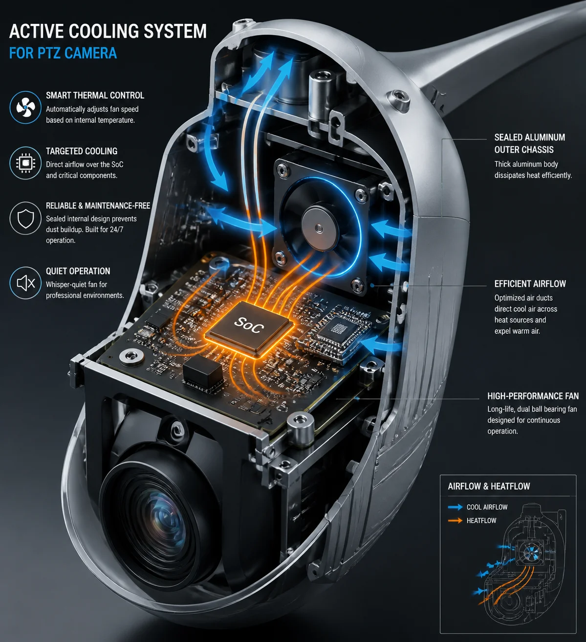 PTZ camera internal active cooling fan dust-proof design
Below, I’ll break down each part of this system. I’ll answer the four questions I hear most from integrators like David Miller who deploy PTZ cameras in dusty, off-grid sites across Texas, Alberta, and the Middle East. Every answer comes from what we’ve learned building these cameras since 2013 at our Shenzhen R&D center.
Table of Contents
Will the Fan’s Bearings Fail if the Camera Is Installed in a Dusty Construction Zone?
I used to worry about this too. A construction site in West Texas throws more dust at a camera in one week than a city rooftop sees in a year. If that dust gets into the bearings, the fan dies. Then the SoC overheats. Then you’re sending a crew out to swap a unit on a 30-foot pole.
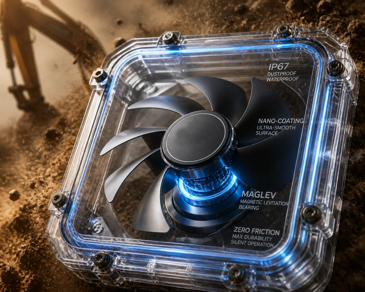
No — the bearings will not fail from dust because the fan sits inside a fully sealed IP66/IP67 chamber. External dust never touches the fan blades or bearings. The fan only circulates internal air across heat sinks and the aluminum chassis. Combined with MagLev or sealed hydraulic bearings rated for 50,000+ hours, the fan runs maintenance-free for 6 to 8 years of continuous operation.
 PTZ camera sealed chamber fan bearing dust protection
Why External Dust Is Not the Real Threat
Most people assume the fan works like a laptop fan — pulling air in from outside, pushing it across a heat sink, and blowing it out the back. If that were true, a dusty construction zone would absolutely destroy the bearings within months. But industrial PTZ cameras don’t work that way.
The fan sits inside a sealed enclosure. Think of it like a fish tank with a small pump inside. The pump moves water around inside the tank, but no outside water ever enters. The same principle applies here. The fan pushes internal air across the SoC processor, the laser driver board, and other hot components. That heated air then touches the inner wall of the aluminum chassis. The chassis acts as a giant heat sink. Heat moves from the air to the metal, and from the metal to the outside atmosphere. At no point does outside air — or outside dust — enter the system. For a detailed explanation of IP66/IP67 sealing requirements, refer to the IEC 60529 ingress protection rating standard 1.
Bearing Technology Comparison
The type of bearing inside the fan matters a lot. Here’s how the three main options compare:
| Bearing Type | Lifespan (Hours) | Dust Resistance | Noise Level | Cost |
|---|---|---|---|---|
| Sleeve (Basic) | 25,000 – 30,000 | Low — needs sealing | Medium | Low |
| Hydraulic (Sealed) | 40,000 – 50,000 | High — fully sealed | Low | Medium |
| MagLev (Magnetic) | 50,000 – 70,000 | Very High — no contact | Very Low | Higher |
At Loyalty-Secu, we use MagLev bearings in our high-end PTZ models. The rotor floats on a magnetic field. There is zero physical contact between moving parts. No contact means no friction. No friction means no wear particles. No wear particles means nothing to gum up the mechanism. Technical data from Sunon’s MagLev fan bearing technology 2 confirms the extended lifespan of magnetic levitation designs in continuous operation.
What About Internal Dust Sources?
This is a question most people forget to ask. Even inside a sealed chamber, there can be micro-particles. Cable insulation can shed tiny fibers over years. PCB conformal coating can flake under extreme thermal cycling. We address this with two measures. First, the anti-static coating I just mentioned. Second, some of our advanced models support a brief reverse-spin cycle at startup. The fan spins backward at high speed for about two seconds. This uses centrifugal force to fling off any micro-particles that may have settled on the blades. It’s a self-cleaning step that happens automatically. You never need to think about it.
Does the Fan Only Activate When the Internal Temperature Hits a Specific Threshold?
I’ve worked with integrators running solar-powered sites where every milliamp counts. If the fan runs 24/7, it drains the battery faster and wears out sooner. Both outcomes cost money.
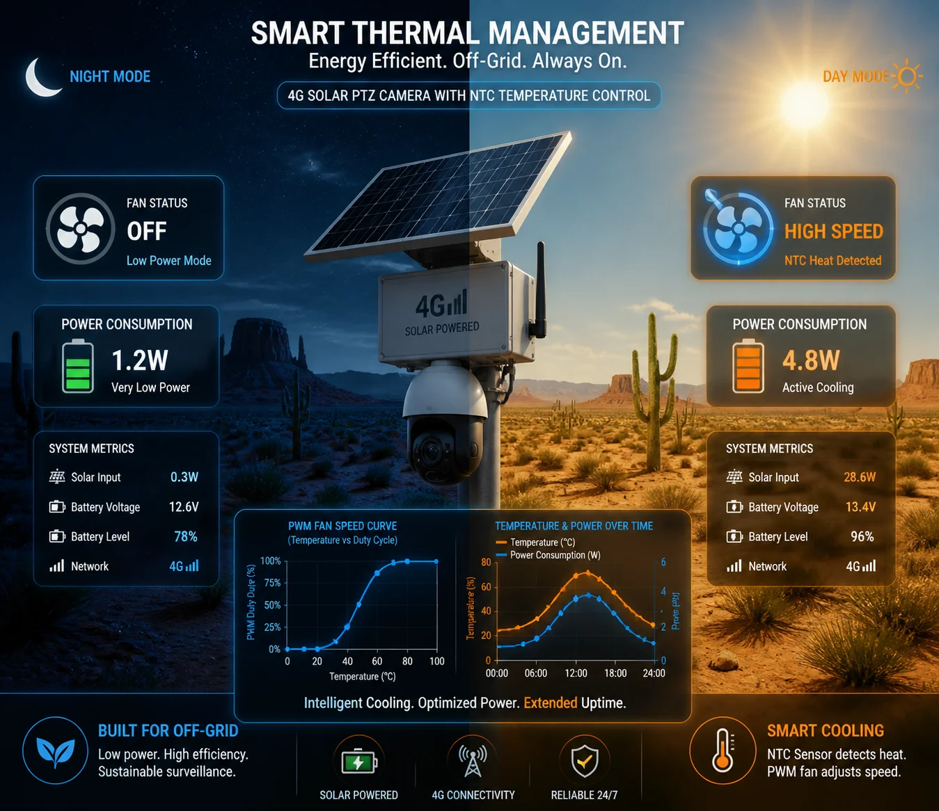
Yes — the fan is controlled by a PWM algorithm linked to an internal NTC temperature sensor. It stays completely off below a set threshold (typically around 40°C–45°C). As temperature rises, the fan speed increases in steps. This on-demand approach cuts total fan runtime by more than half, which directly extends both bearing life and battery life in solar-powered deployments.
 PTZ camera smart fan temperature threshold PWM control
How the Temperature Control Logic Works
The system uses one or more NTC (Negative Temperature Coefficient) thermistors placed near the hottest components — usually the main SoC processor and the power regulation module. The MCU reads these sensors continuously. Based on the reading, it sends a PWM (Pulse Width Modulation) signal to the fan motor. A higher duty cycle means faster spinning. A lower duty cycle means slower spinning. Below the threshold, the duty cycle is zero — the fan is off. The PWM fan speed control standard 3 has been widely adopted in industrial cooling applications.
Here is a typical temperature-to-fan-speed mapping:
| Internal Temperature | Fan Speed | Power Draw | Purpose |
|---|---|---|---|
| Below 40°C | Off (0 RPM) | ~0 mA | Save power, zero wear |
| 40°C – 50°C | Low (30% PWM) | ~50 mA | Gentle air movement |
| 50°C – 60°C | Medium (60% PWM) | ~120 mA | Active cooling for sustained load |
| Above 60°C | Full (100% PWM) | ~200 mA | Maximum cooling, thermal protection |
Dual-Trigger Logic: Load + Temperature
Some of our models go beyond simple temperature thresholds. They also monitor the processing load. If the camera is encoding at a high bitrate — say, 8 Mbps H.265 at 30fps with AI analytics running — the SoC generates more heat even before the thermistor registers a spike. The firmware anticipates this. It starts the fan at low speed preemptively, preventing a sudden temperature jump. This smoother thermal curve is easier on the components and avoids the stress of rapid heating and cooling cycles.
Why This Matters for Solar Sites
On a 4G solar-powered PTZ system, the battery bank is sized for a specific daily power budget. Every component that draws current affects how many panels and batteries you need. If the fan ran at full speed 24 hours a day, it would add roughly 4.8 Wh per day to the power budget. That might sound small, but in a winter scenario with only 3–4 hours of usable sunlight, it can be the difference between the system staying alive through the night or shutting down at 4 AM.
By keeping the fan off during cool nights and low-load periods, the smart control logic effectively makes the fan’s average power draw close to zero for large portions of the day. This is not just a nice feature. For off-grid deployments, it is a hard requirement. For power budgeting guidance, consult solar power calculation resources for remote security cameras 4.
The Self-Cleaning Burst
I mentioned the reverse-spin cycle earlier. It ties into the control logic too. On some models, the firmware triggers a 2-second high-speed burst every 24 hours or at every power-on event. This burst serves two purposes: it clears any settled micro-debris from the blades, and it gives the system a chance to check the fan’s health. If the fan fails to reach the expected RPM during this burst, the system logs a fault. More on that in the alert section below.
How Does the “Sealed-Chamber” Design Prevent Dust from Reaching the Lens or Sensor?
I’ve opened up cameras from other brands after 18 months in the field. Dust on the sensor. Dust on the lens rear element. Haze in every image. The customer blamed the camera. But the real problem was the airflow design — it pulled dirty air right across the optics.
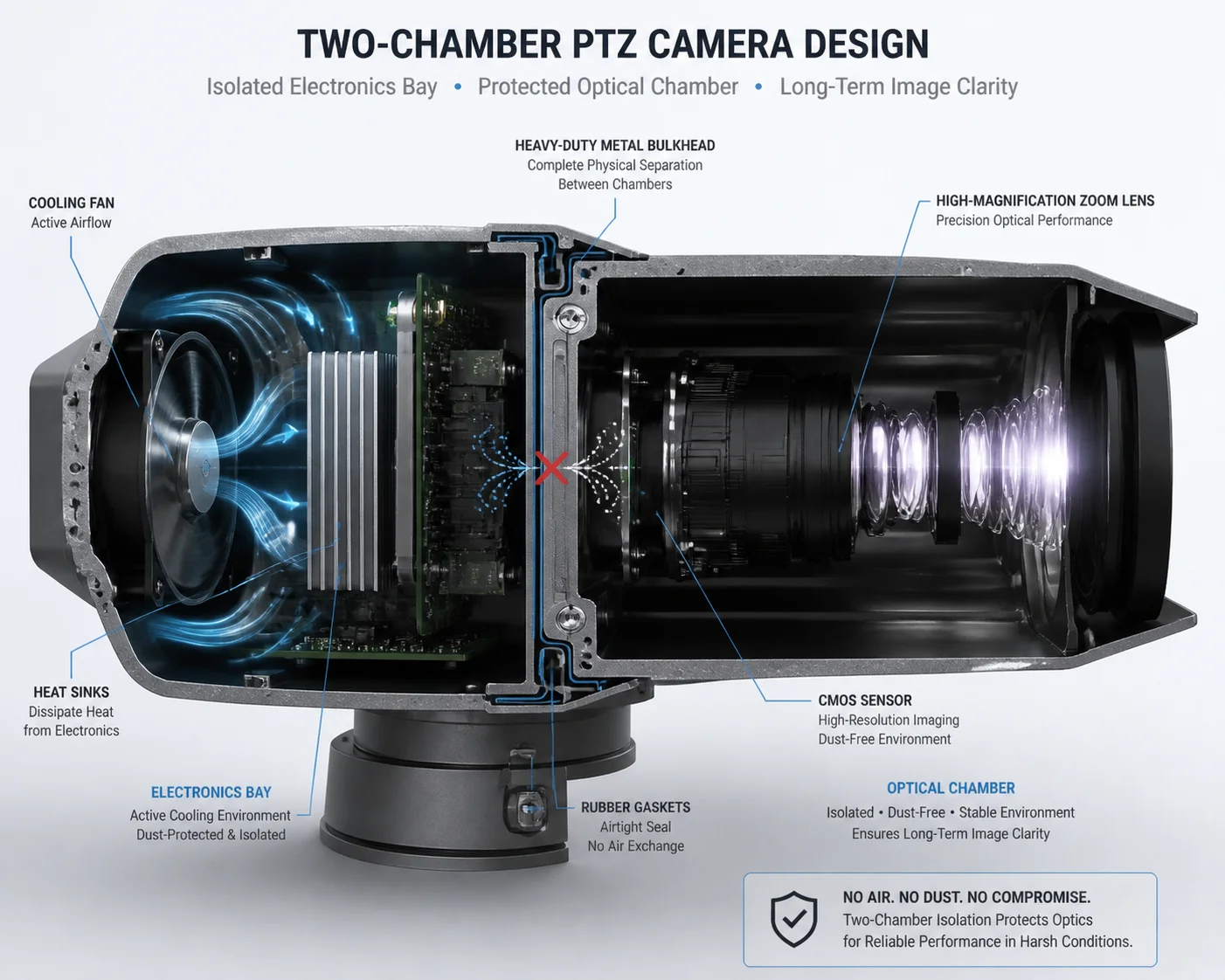
The sealed-chamber design uses physical compartmentalization. The optical module — lens, sensor, and IR-cut filter — sits in its own isolated cavity, separated from the electronics bay by gaskets and bulkhead seals. The cooling fan operates only in the electronics bay. No airflow path connects the fan chamber to the optical chamber. This means even internal air movement cannot carry particles onto the lens or sensor surface.
 PTZ camera sealed optical chamber dust isolation design
Two Chambers, Two Jobs
Think of the camera as two sealed boxes joined together but not connected inside. Box one holds the electronics: the SoC, power supply, video encoder, 4G module, and the cooling fan. Box two holds the optics: the zoom lens assembly, the CMOS sensor, the IR-cut filter, and the laser illuminator window. A metal bulkhead with rubber gaskets sits between them. Wiring passes through sealed connectors or potted cable glands. Air does not pass through. This design principle aligns with best practices for optical component protection in industrial cameras 5.
This separation is the single most important design choice for long-term image quality. It doesn’t matter how good your fan dust-proofing is if dirty air can reach the sensor. By making the optical chamber its own sealed environment, we remove that risk entirely.
The Airflow Path Inside the Electronics Bay
Inside the electronics bay, the fan creates a circular airflow pattern. Air moves from the fan across the SoC heat sink, along the inner wall of the chassis, and back to the fan intake. The chassis wall is the heat exchanger. On the outside, the aluminum housing has fins or a large flat surface area exposed to ambient air and wind. Heat transfers through the metal by conduction, then dissipates to the atmosphere by convection and radiation.
Here is how the two chambers compare:
| Feature | Electronics Bay | Optical Chamber |
|---|---|---|
| Contains fan | Yes | No |
| Sealed from outside | Yes (IP66/IP67) | Yes (IP66/IP67) |
| Connected to each other | No — bulkhead sealed | No — bulkhead sealed |
| Heat sources | SoC, power supply, laser driver | Minimal (sensor only) |
| Dust risk to image | None — no optics here | Eliminated — no airflow from fan |
| Cooling method | Internal fan + chassis conduction | Passive conduction through housing |
What About the Pan-Tilt Rotation Joints?
This is a smart question that experienced integrators always ask. The PTZ camera rotates 360° on the pan axis and up to 90° or more on the tilt axis. Every rotation joint is a potential entry point for dust and water. We handle this with multi-layer labyrinth seals and silicone O-rings at every joint. The slip ring — which passes power and data signals through the rotating joint — is also enclosed in its own sealed sub-chamber. The slip ring never shares airspace with the optical module.
Positive Pressure Consideration
Some industrial camera designs use a slight positive internal pressure to push air outward through any micro-gaps, preventing dust from being sucked in. In a fully sealed IP66/IP67 design, this is less critical because there should be no gaps at all. However, thermal expansion and contraction of the internal air can create slight pressure differences. Our housing design accounts for this with a small Gore-Tex-style pressure equalization vent — it allows air pressure to equalize without letting liquid water or dust particles pass through. This prevents seal stress during extreme temperature swings, like a desert day-to-night cycle of 50°C to 5°C. For more on pressure equalization vents, see Gore’s protective venting technology for sealed enclosures 6.
Is There an Alert System That Notifies Me if the Cooling Fan Has Stopped Rotating?
I’ve had a customer lose three cameras in one summer because the fans failed silently. No alert. No log entry. The SoC just cooked until the firmware crashed. By the time anyone noticed, the boards were damaged. Three truck rolls. Three replacements. That’s a $6,000 lesson.
Yes — the system monitors fan speed through a Hall-effect tachometer signal fed back to the MCU. If the fan fails to spin or drops below a minimum RPM threshold, the firmware triggers an immediate alert via SNMP trap, email notification, or platform alarm through ONVIF event subscription. Simultaneously, the system enters a thermal protection mode — reducing SoC clock speed and encoding bitrate to lower heat output and prevent hardware damage.
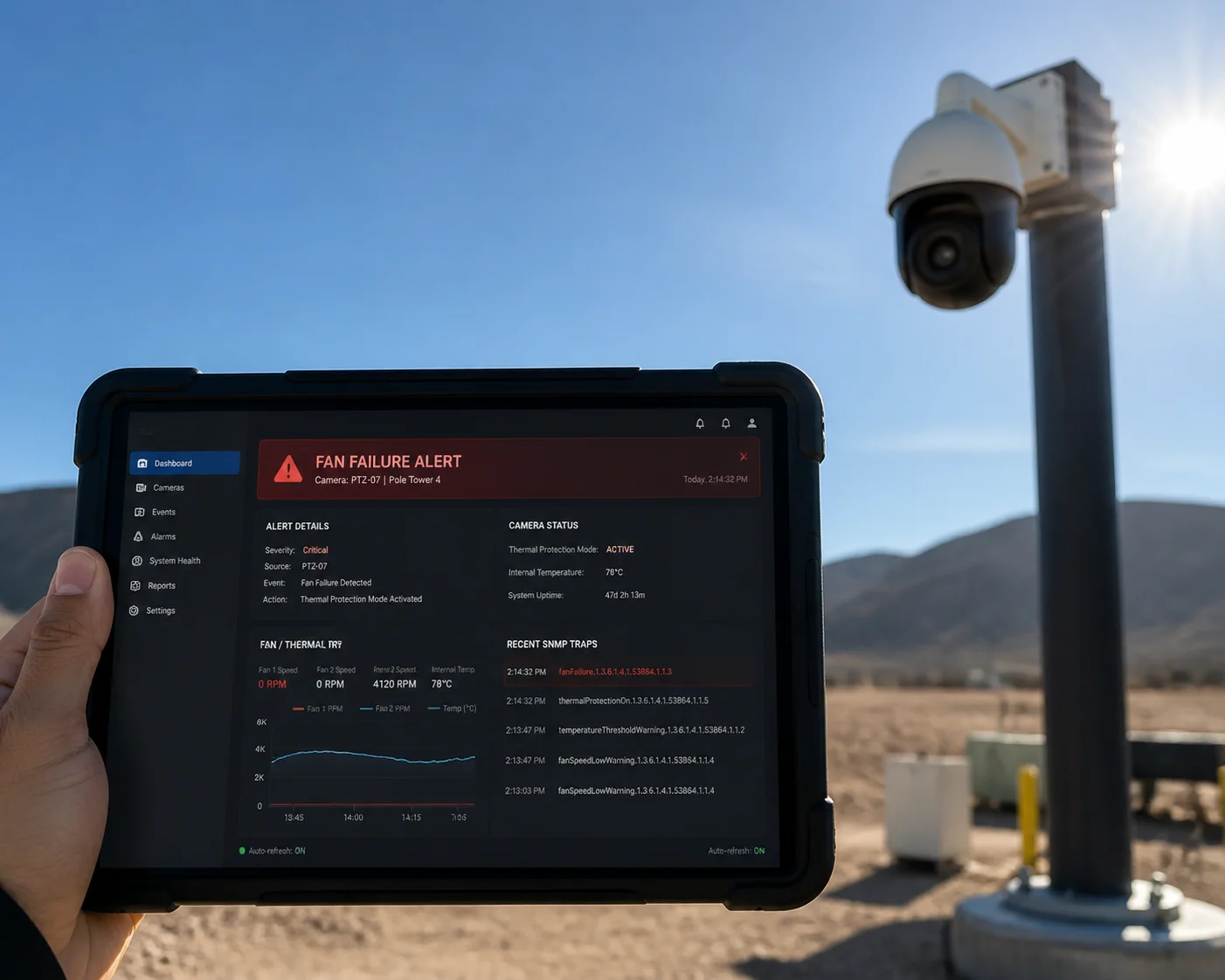 PTZ camera fan failure alert SNMP notification system
How Fan Health Monitoring Works
Every fan we use has a built-in Hall-effect sensor. This sensor generates a pulse signal each time the rotor completes a revolution. The MCU counts these pulses per second to calculate RPM. This is not an estimate — it is a direct, real-time measurement of actual fan speed.
The firmware compares the measured RPM against the expected RPM for the current PWM duty cycle. If the fan should be spinning at 3,000 RPM but is only hitting 1,200 RPM, something is wrong. Maybe the bearing is starting to seize. Maybe a wire connection is loose. The system flags this as a “fan degradation” event. If the RPM drops to zero while the PWM signal is active, the system flags it as a “fan failure” event.
Alert Delivery Methods
Different integrators use different monitoring platforms. We support multiple alert channels to fit into existing workflows:
- SNMP Trap: For integrators using network management systems like Nagios, PRTG, or SolarWinds. The camera sends an SNMP v2c or v3 trap to the configured manager IP. The trap includes the OID for fan status, current temperature, and device serial number. The SNMP standard for network device monitoring 7 provides the framework for these alerts.
- Email Notification: For smaller operations without a full NMS. The camera sends an email directly to a configured address. The subject line includes the device name and alert type. Simple and effective.
- ONVIF Event Subscription: For integrators using VMS platforms like Milestone or Genetec. The camera publishes fan failure as an ONVIF event. The VMS picks it up and displays it in the alarm dashboard alongside motion events and analytics alerts. Reference the ONVIF event handling specification 8 for implementation details.
- Platform API / Webhook: For custom-built monitoring dashboards. We provide an HTTP webhook option that posts a JSON payload to a specified URL when a fan event occurs.
Thermal Protection Mode
The alert is only half the story. The other half is what the camera does to protect itself. When a fan failure is detected, the firmware enters thermal protection mode. It takes three steps. First, it reduces the SoC clock frequency. This lowers processing power but also lowers heat output. Second, it drops the encoding bitrate and frame rate — for example, from 8 Mbps at 30fps down to 4 Mbps at 15fps. Third, it may disable non-essential features like on-board AI analytics to further reduce thermal load.
The goal is to keep the camera alive and streaming — even at reduced quality — until a technician can address the issue. This is far better than a silent death that leaves you with a black screen and no idea why. Best practices for remote equipment monitoring and alert management 9 emphasize the importance of proactive failure detection.
Why This Matters for Remote Sites
For a 4G solar-powered camera on a pipeline right-of-way or a remote construction perimeter, the nearest technician might be a 4-hour drive away. Silent failures are the enemy. Every alert that reaches the NOC before the hardware is damaged saves a truck roll. At $500 to $1,500 per truck roll in rural North America, fan health monitoring pays for itself the first time it fires.
At Loyalty-Secu, we treat these alerts as a core feature, not an afterthought. Our firmware team tests every alert path during the 48-hour burn-in aging test that every camera goes through before it ships. If the alert doesn’t fire reliably in our test chamber, the camera doesn’t leave the factory.
Conclusion
The dust-proof and maintenance-free logic is not one single trick. It is a system — sealed chambers block dust, MagLev bearings eliminate wear, smart PWM control cuts unnecessary runtime, and real-time fan monitoring catches failures before they cause damage. That is how you get 6+ years of hands-off operation in the harshest field conditions.
1. IEC 60529 international standard for IP ingress protection ratings. ↩︎ 2. Sunon MagLev bearing technology specifications and lifespan data. ↩︎ 3. Intel PWM fan speed control standard for thermal management. ↩︎ 4. Solar-electric learning center — power budget calculations for remote sites. ↩︎ 5. Edmund Optics guide to environmental protection for optical systems. ↩︎ 6. Gore protective venting technology for sealed industrial enclosures. ↩︎ 7. IETF SNMP standard for network device monitoring and alerts. ↩︎ 8. ONVIF event handling specification for VMS integration. ↩︎ 9. DPS Telecom best practices for remote equipment monitoring. ↩︎