
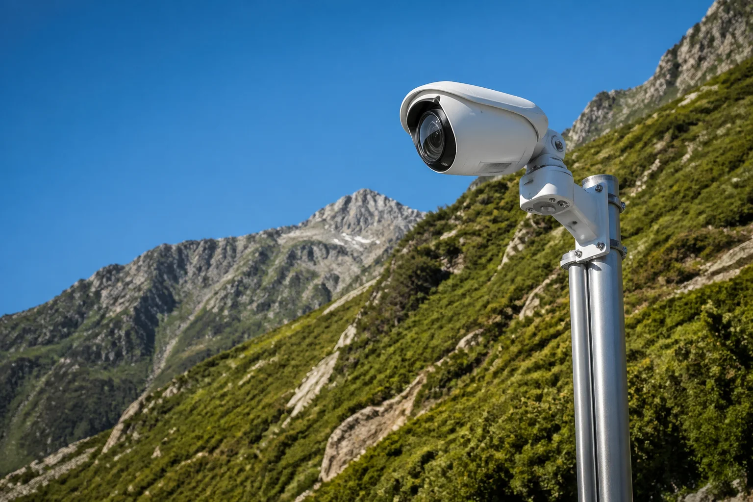
I have seen too many PTZ cameras fail on hillside jobs. The camera sits on a pole, but it cannot look up. Everything above the mount point becomes a blind spot. That one missing spec — tilt range — kills the whole project.
A -15° to 90° tilt range lets a PTZ camera look 15° above the horizon and straight down to the ground. This means one camera can cover uphill targets, distant ridgelines, and the ground directly below the mount point — all from a single position. For hillside, slope, and elevated installations, this range removes blind spots that standard 0° to 90° cameras simply cannot reach.
 PTZ camera tilt range hillside monitoring advantages
Below, I will break down each real-world question I get from integrators and project managers about this tilt spec. I will explain what it means in the field, why it matters for your project budget, and how to avoid the mistakes I see on hillside deployments every month.
Can My Camera See “Above the Horizon” to Monitor Uphill Traffic or Higher Floors?
I get this question a lot from integrators working on slope roads and multi-level buildings. They mount a PTZ on a mid-slope pole, and then realize it cannot tilt up to see the road above.
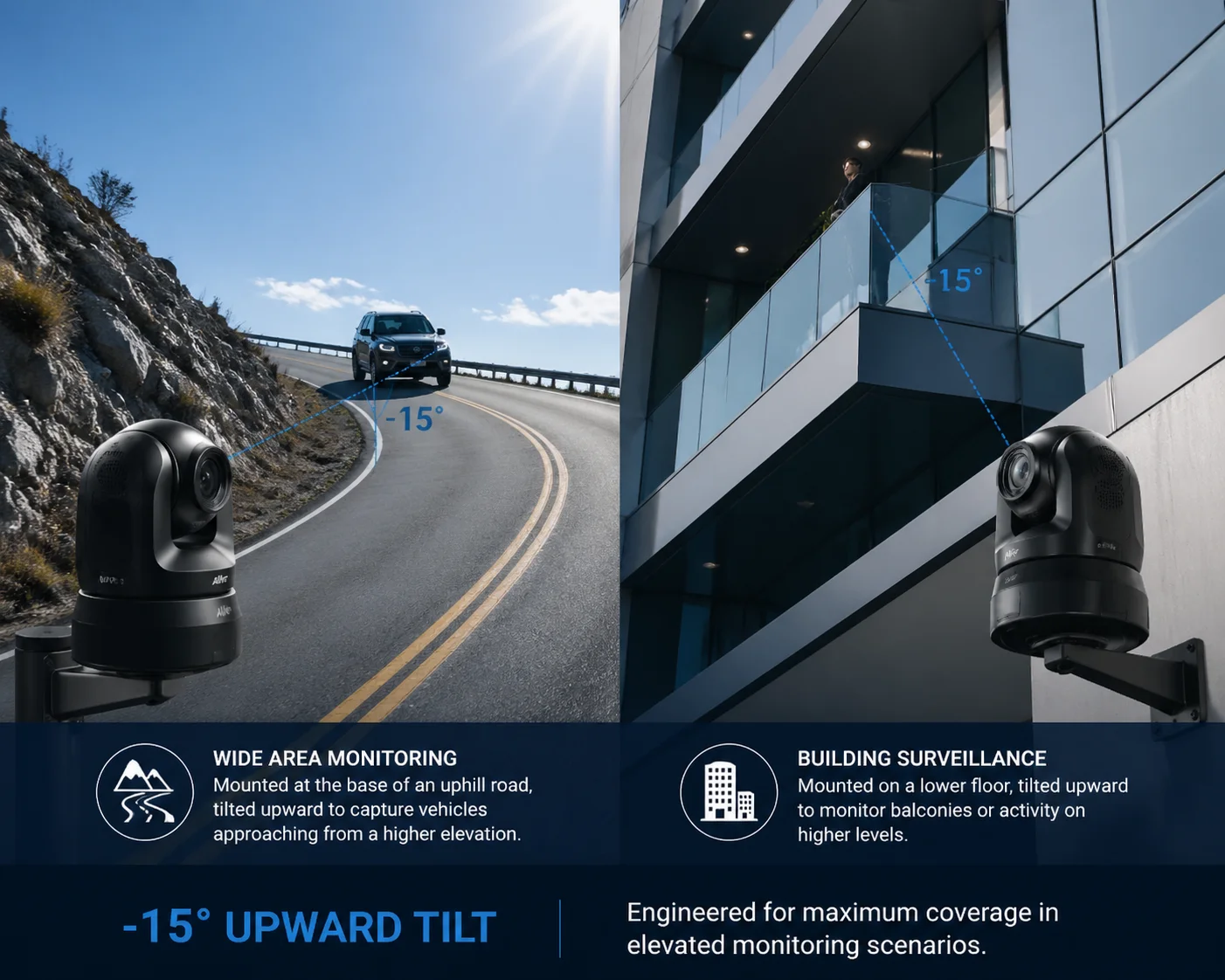
Yes. A camera with -15° tilt can look 15 degrees above the horizontal plane. This lets you monitor uphill roads, higher building floors, or ridgelines that sit above your camera’s mount point. Standard PTZ cameras with a 0° minimum tilt cannot do this at all.
 PTZ camera uphill tilt above horizon monitoring
Why 0° Is Not Truly “Horizontal” in the Field
On paper, 0° tilt means the camera looks straight out at the horizon. But in real installations, “horizontal” is rarely flat. Here is what happens:
When you mount a PTZ on a pole on a hillside, the pole itself may lean slightly. The mounting bracket may add a small downward angle. And the terrain in front of the camera rises. So even at 0° tilt, the camera is already looking slightly below the targets you care about.
I have seen this on job sites in hilly regions. An integrator sets the camera to 0° tilt and zooms to 33X to check a fence line 400 meters away on a slope. The fence line sits at the very bottom edge of the frame — or it is completely out of view. The camera needs to tilt up by 5° to 10° just to center the target. Without the -15° capability, that is impossible.
The Math Behind Uphill Coverage
Let me put some numbers to this. Say your camera is mounted on a 6-meter pole at the bottom of a slope. The slope rises at 10° over 300 meters. The target — a gate or fence — sits at the top of that slope.
| Mount Height | Slope Angle | Target Distance | Required Upward Tilt | Standard PTZ (0° min) | -15° PTZ |
|---|---|---|---|---|---|
| 6 m | 5° | 200 m | ~3° above horizon | ❌ Cannot reach | ✅ Covered |
| 6 m | 10° | 300 m | ~8° above horizon | ❌ Cannot reach | ✅ Covered |
| 6 m | 15° | 400 m | ~12° above horizon | ❌ Cannot reach | ✅ Covered |
| 10 m | 10° | 500 m | ~7° above horizon | ❌ Cannot reach | ✅ Covered |
As you can see, even a gentle 5° slope creates a problem at 200 meters. The target goes above the horizon line from the camera’s perspective. A standard PTZ simply cannot look there.
Multi-Story Building Monitoring
This same logic applies to buildings. If your camera is mounted on the 3rd floor and you need to monitor activity on the 5th floor of a building across the street, you need upward tilt. Without it, the upper floors are invisible. The -15° range gives you that reach without needing to relocate the camera to a higher position.
What This Means for Your Project Budget
If your PTZ cannot tilt up, you have two choices: mount the camera higher (which costs more for the pole, labor, and crane), or add a second camera. Both options increase your project cost. A single PTZ with -15° tilt solves the problem at the hardware spec level. No extra pole. No extra camera. No extra SIM card or solar panel.
How Does the -15° Tilt Help Eliminate Blind Spots When the Camera Is Mounted High?
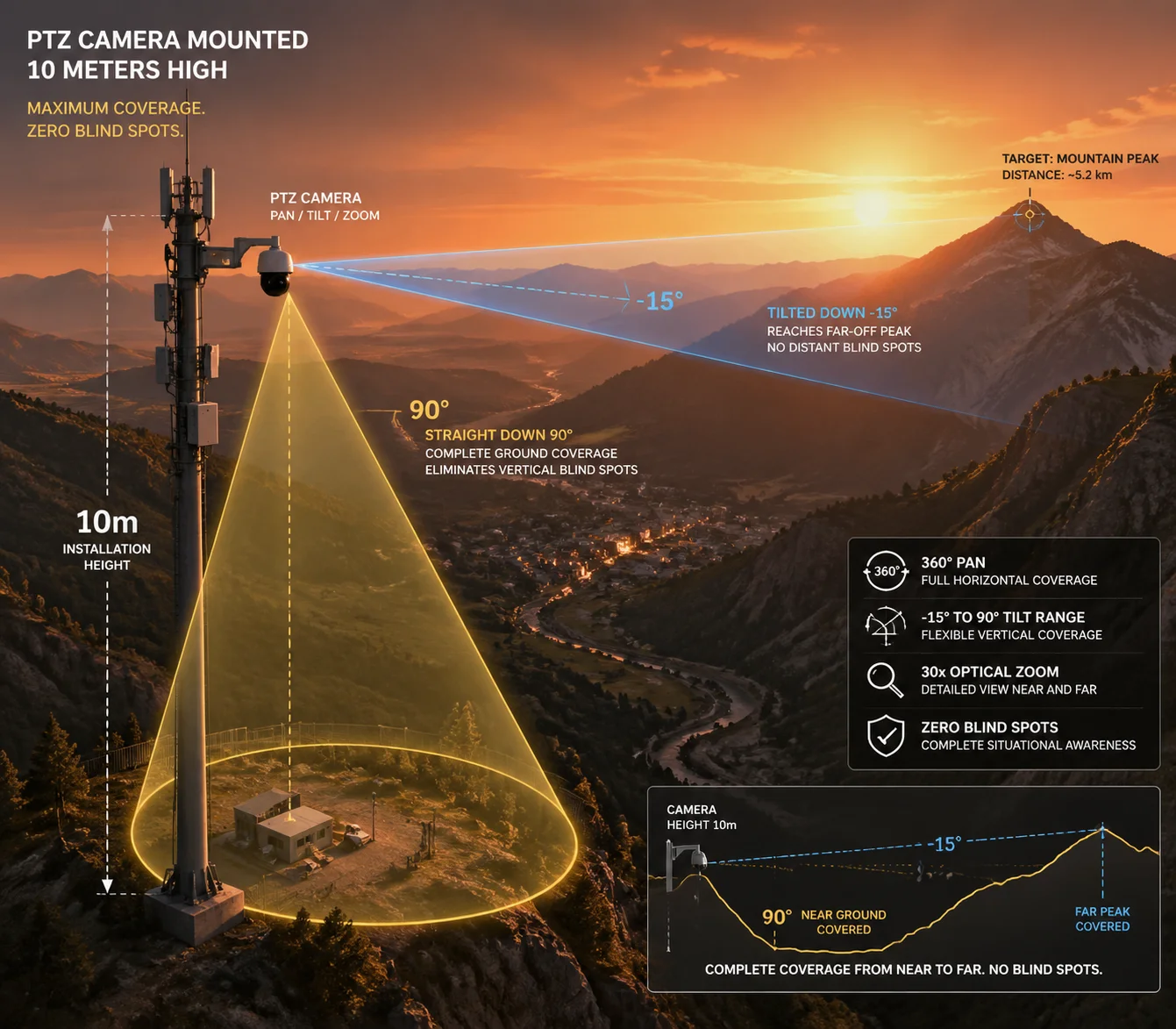
I have walked job sites where a PTZ sits 10 meters up on a pole, and the client complains about blind spots. The camera can see far away, but it misses the area right below and — surprisingly — the area far in the distance at the horizon line.
When a camera is mounted high, the -15° upward tilt lets it look out toward the far horizon instead of only looking downward. Combined with the 90° downward tilt for close-range coverage directly below, the full -15° to 90° range eliminates both the “too far” and “too close” blind spots that plague high-mount installations.
 PTZ camera high mount blind spot elimination tilt range
The Two Blind Spots of High-Mount PTZ Cameras
Most people think mounting a camera high gives you better coverage. That is partly true. Height gives you a wider field of view and reduces obstructions. But it also creates two specific blind spots:
Blind Spot 1: Directly Below the Camera When the camera is at 0° tilt (horizontal), it looks out into the distance. The ground directly below the pole — within a 5 to 15 meter radius — is invisible. To see this area, the camera must tilt down to 80° or 90°. Most PTZ cameras handle this fine.
Blind Spot 2: The Far Horizon This is the one people miss. When a camera is mounted at 10 meters on a hilltop, and the terrain drops away in front of it, the horizon line actually sits above the camera’s 0° horizontal plane relative to distant targets. The camera needs to tilt slightly upward to see the farthest points on the landscape. Without -15° tilt, those distant targets fall out of frame.
How -15° to 90° Covers the Full Vertical Plane
Think of the camera’s tilt range as a vertical arc. Here is how the coverage breaks down:
| Tilt Angle | What the Camera Sees | Use Case |
|---|---|---|
| -15° (upward) | Sky, ridgelines, upper slopes, higher floors | Monitoring uphill fence lines, distant horizon |
| 0° (horizontal) | Mid-distance terrain, roads, perimeter lines | General surveillance at medium range |
| 45° (downward) | Near-to-mid ground area, pathways, parking lots | Tracking people and vehicles approaching |
| 90° (straight down) | Ground directly below the camera pole | Checking the base of the pole, nearby walls, drainage |
This full arc means one camera can sweep from the sky above to the ground below. In a hillside deployment, this is not a luxury — it is a necessity.
Preset Patrol for Full Vertical Coverage
In practice, I recommend setting up at least three preset positions to exploit this range:
- Preset 1: -10° tilt — aimed at the upper ridge or distant road. This is your early warning position. You see vehicles or people approaching from far away.
- Preset 2: 0° to 20° tilt — aimed at the mid-range perimeter. This is your main monitoring zone.
- Preset 3: 75° to 90° tilt — aimed straight down. This checks the base of the installation, the solar panel condition, or the drainage channel below.
With auto-cruise, the camera rotates through these presets every 30 to 60 seconds. One camera. Full vertical coverage. No blind spots.
Real-World Example: Valley Monitoring
Picture a solar-powered 4G PTZ mounted on a ridge overlooking a valley. The valley floor is 80 meters below. The opposite ridge is 600 meters away and 20 meters higher than the camera.
A standard 0° to 90° PTZ can see the valley floor (by tilting down) and the mid-slope (at 0°). But the opposite ridge? It sits above the horizontal plane. The camera cannot see it. You would need a second camera on a taller pole — or you would need to move the camera to a higher point.
With -15° tilt, the camera simply looks up 10° to 12° and captures the opposite ridge. One camera. One pole. One solar panel. One SIM card. The cost savings are obvious.
Will the Image Auto-Flip Correctly When the Camera Tilts Past the 90° Vertical Point?
I have had clients ask me this after reading spec sheets that mention “auto-flip” or “auto-reverse.” They worry the image will appear upside down or mirrored when the camera tilts to extreme angles.
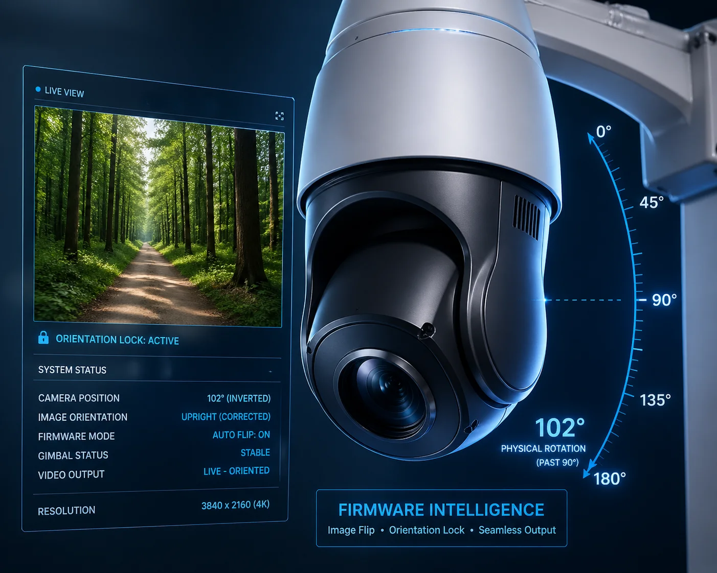
Yes, a properly engineered PTZ camera will auto-flip the image when it passes through the 90° vertical point or when it is ceiling-mounted in an inverted position. The firmware detects the orientation and corrects the image so it always appears right-side-up on your monitor or VMS platform.
 PTZ camera auto flip image correction tilt 90 degrees
How Auto-Flip Works Mechanically and in Firmware
When a PTZ camera tilts past 90° (straight down), the mechanical gimbal reaches its physical limit. Some cameras use a feature called “auto-reverse” to handle this. Here is what happens:
- The camera tilts to 90° (straight down).
- The operator or preset tries to tilt further.
- The camera’s pan motor rotates 180° horizontally.
- The tilt motor reverses direction.
- The firmware flips the image so it stays right-side-up.
This all happens in about 1 to 2 seconds. The result is that the camera can effectively look “past” the 90° point without the image going upside down. For the operator, it feels seamless.
Why This Matters for Inverted (Ceiling/Overhang) Mounting
On hillside projects, you sometimes need to mount the camera under an overhang, a bridge deck, or a ceiling inside a tunnel. In these cases, the camera hangs upside down. Without auto-flip, every image would be inverted.
Good PTZ cameras — and I am talking about industrial-grade units, not consumer toys — detect the inverted mount automatically. The firmware flips the image. The tilt controls also reverse so that “up” on your joystick still means “up” on the screen.
What to Check Before You Buy
Not all auto-flip implementations are equal. Here is what I tell my clients to verify:
- Does the flip happen automatically, or do you need to set it manually in the menu? Automatic is better. Manual means every camera needs individual configuration, which adds labor on large projects.
- Does the flip work with all video streams? Some cameras flip the main stream but not the sub-stream. This causes problems when your VMS uses the sub-stream for live view.
- Does the flip affect OSD (on-screen display) text? On cheap cameras, the OSD text also flips and becomes unreadable. On good cameras, the OSD stays correct regardless of orientation.
- Does the auto-reverse cause a visible “jump” in recorded video? On well-engineered cameras, the transition is smooth. On poorly made ones, you get a 1-2 second black screen or a jarring image jump.
Compatibility with VMS Platforms
If your client uses Milestone 1, Blue Iris 2, or another major VMS, the auto-flip must work at the protocol level. The camera should send the corrected image via ONVIF or RTSP. The VMS should not need any special plugin or driver to display the flipped image correctly. I always test this before shipping a batch to an integrator. A camera that works perfectly on its own web interface but sends an inverted stream via ONVIF is useless in a professional deployment.
Is the Tilt Motor Powerful Enough to Maintain a -15° Angle Against Gravity and Wind?
This is the question that separates engineers from salespeople. Anyone can print “-15° to 90°” on a spec sheet. But can the motor actually hold that position in a 60 km/h crosswind on a mountain ridge? I have tested this, and the answer depends entirely on the motor and gear design.
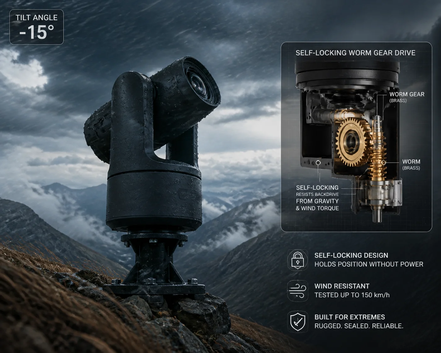
A properly designed industrial PTZ uses a worm gear or self-locking gear mechanism in the tilt motor. This means the motor can hold any position — including the -15° upward angle — without drifting, even under strong wind loads. Consumer-grade cameras with simple spur gears will drift or vibrate at extreme tilt angles, especially in outdoor conditions.
 PTZ camera tilt motor wind resistance worm gear mechanism
Why -15° Is the Hardest Angle to Hold
At 0° tilt (horizontal), gravity pulls the camera housing straight down. The tilt motor only needs to resist a small torque. At 90° (straight down), gravity actually helps — the camera hangs naturally, and the motor barely works.
But at -15° (looking upward), the camera housing is tilted against gravity. The weight of the lens, the IR illuminator, and the housing all create a torque that tries to pull the camera back down toward 0°. The motor must actively resist this force — continuously.
Now add wind. On a mountain ridge or open hillside, sustained winds of 40 to 80 km/h are common. Wind hitting the camera dome creates additional torque on the tilt axis. If the motor or gear system is weak, the camera will:
- Drift slowly downward from -15° toward 0°
- Vibrate or oscillate, causing blurry images
- Make grinding noises as the gears slip
Worm Gear vs. Spur Gear: The Critical Difference
The type of gear in the tilt mechanism determines whether the camera can hold its position:
| Feature | Worm Gear 3 (Industrial) | Spur Gear 4 (Consumer) |
|---|---|---|
| Self-locking | Yes — holds position without power | No — can slip under load |
| Wind resistance | High — resists external torque | Low — vibrates in wind |
| Position accuracy | ±0.1° | ±1° or worse |
| Noise level | Low | Higher, especially under load |
| Cost | Higher | Lower |
| Lifespan | 50,000+ hours | 10,000-20,000 hours |
At Loyalty-Secu, we use worm gear mechanisms in our PTZ tilt assemblies. This is not a marketing choice — it is an engineering requirement. A worm gear is self-locking by design. Even if you cut power to the motor, the camera stays at -15°. Gravity cannot back-drive the gear. Wind cannot push it off position.
What Happens When Cheap Motors Fail
I have seen the results of cheap tilt motors on hillside projects. Here is a typical failure sequence:
- The integrator installs the camera and sets a preset at -10° to monitor an uphill road.
- For the first few weeks, it works fine.
- After a month of wind exposure, the gear teeth start to wear.
- The camera begins drifting 2° to 3° from the preset position.
- The 33X zoom image, which was centered on a gate 400 meters away, now shows empty sky.
- The client calls the integrator. The integrator drives 2 hours to the site. He resets the preset. It drifts again within a week.
- The integrator replaces the camera. Total cost: the camera price plus two truck rolls plus lost client trust.
This is why I always tell my clients: the tilt motor spec is not just about range. It is about holding force, gear type, and long-term reliability. A -15° spec means nothing if the motor cannot hold -15° after six months of outdoor exposure.
Testing Protocol I Recommend
Before you commit to a large order, ask your supplier to do this test:
- Set the camera to -15° tilt.
- Apply a 5 kg side load to the dome (simulating wind).
- Leave it for 24 hours.
- Check if the tilt angle has drifted.
If the supplier cannot or will not do this test, that tells you something about their confidence in the product.
Conclusion
A -15° to 90° tilt range is not a luxury spec — it is a practical requirement for any hillside, slope, or elevated PTZ deployment. It eliminates uphill blind spots, reduces the number of cameras you need, and saves real money on poles, labor, and truck rolls. Check the gear type, test the holding force, and verify auto-flip compatibility with your VMS before you buy.
1. Milestone XProtect PTZ preset configuration guide. ↩︎ 2. Blue Iris PTZ auto-flip and image correction settings. ↩︎ 3. Worm gear self-locking principle for tilt retention. ↩︎ 4. Spur gear backlash and wind-induced drift in PTZ cameras. ↩︎ 5. Slope angle calculation for hillside camera coverage. ↩︎ 6. Preset tour programming for vertical coverage optimization. ↩︎ 7. ONVIF Image Settings service for auto-flip configuration. ↩︎ 8. Gear train efficiency under continuous wind load conditions. ↩︎ 9. PTZ tilt motor torque vs camera weight calculations. ↩︎ 10. IP66 dome aerodynamics and wind torque on tilt axis. ↩︎