
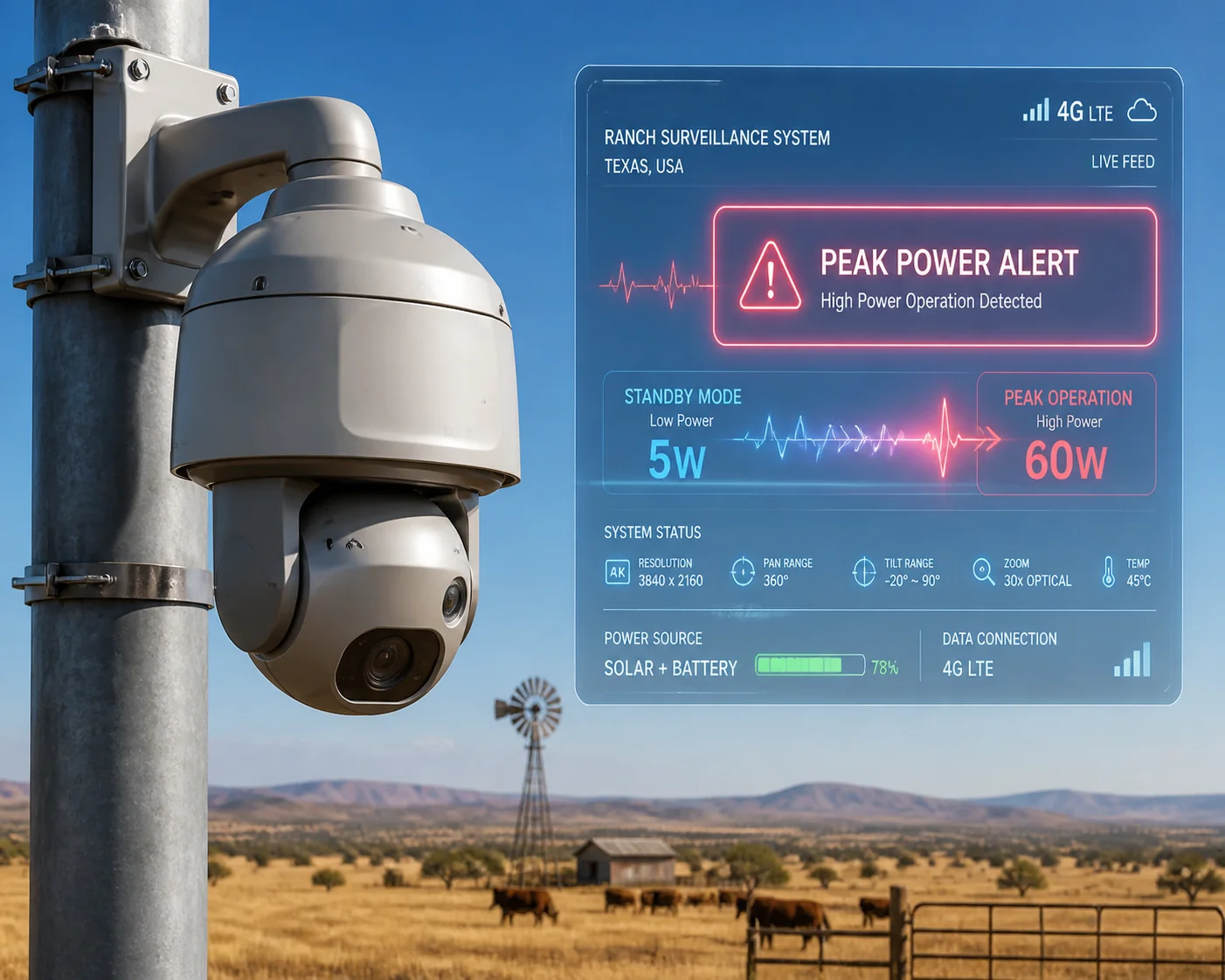
I’ve seen solar PTZ systems shut down mid-summer because someone underestimated peak wattage. That one mistake cost a full truck roll to a remote Texas ranch.
A low-power 4K 4G PTZ system typically draws 3–8 W on average but can spike to 15–25 W when the IR LEDs, pan-tilt motors, and 4G uplink all run at the same time. Thermal management relies on cast-aluminum housings as passive heatsinks, with firmware-level thermal throttling kicking in above 85°C to protect the SoC.
 low power 4K 4G PTZ camera peak power and thermal management data
Below, I break down the exact numbers for each operating mode, explain how heat is handled during 24/7 uploads, cover battery sleep-mode thresholds, and share a day-versus-night power chart. Every figure comes from real product specs and field data we see at Loyalty-Secu.
Table of Contents
What Is the Maximum Wattage My Camera Draws When the 4G, PTZ, and IR Are Active?
I get this question on almost every call with integrators planning off-grid projects. The answer decides your solar panel size, battery bank, and charge controller rating.
When 4G transmission, PTZ motor movement, and IR illumination all run together, a low-power 4K system peaks at 15–20 W. Some models with high-power laser IR can briefly touch 25 W. This is the number you must use to size your power system, not the average.
 4K PTZ camera peak wattage with 4G IR and PTZ active
Why Peak Wattage Matters More Than Average
Most data sheets show “typical” power. That number is misleading for off-grid work. Your battery does not care about the average. It cares about the worst-case spike. If the battery cannot deliver enough current during a 20 W burst, the voltage sags. When voltage sags, the 4G module loses its connection and reboots. I have seen this happen on job sites where the integrator sized everything around a 5 W average. The camera worked fine during the day. At night, the IR turned on, the PTZ tracked a vehicle, and the 4G tried to push a clip. The system pulled 18 W for about four seconds. The battery voltage dropped below the 4G module’s minimum input. The module reset. The clip never uploaded.
Breaking Down Each Power Consumer
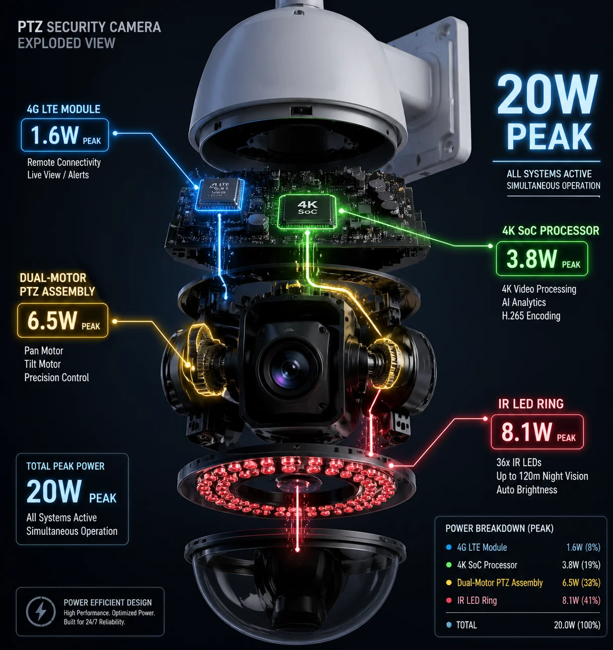
Here is how the wattage stacks up for each subsystem in a typical low-power 4K 4G PTZ camera:
| Subsystem | Idle / Standby | Active (Typical) | Peak (Worst Case) |
|---|---|---|---|
| 4K Video SoC (H.265 encoding) | 0.5 W | 2 – 3 W | 4 W |
| 4G LTE Module (Cat.1 / Cat.4) | 0.1 W | 1 – 2 W | 3 W |
| IR LED Array (850 nm / 940 nm) | 0 W | 5 – 7 W | 10 W |
| PTZ Motors (Pan + Tilt + Zoom) | 0 W | 3 – 5 W | 8 W |
| Misc (MCU, PIR, heater, fan) | 0.05 W | 0.5 W | 1.5 W |
| Total | ~0.65 W | ~12 – 17 W | ~20 – 25 W |
The 20 W Rule
At Loyalty-Secu, we tell every customer the same thing: budget for 20 W peak. Even if your camera’s data sheet says “Max 18 W,” real-world conditions add up. A cold battery has higher internal resistance. A weak 4G signal forces the module to boost its transmit power. A fast preset tour drives both pan and tilt motors at once. All of these push the peak higher than the lab number.
How to Use This Data
Size your solar charge controller for at least 20 W continuous output. Pick a battery with a discharge C-rate that can handle 20 W without dropping below 11 V (for a 12 V system). Add a 20–30% margin if you deploy in extreme cold, because lithium cells lose capacity below 0°C. This approach prevents the most common field failure I see: random 4G disconnections caused by voltage sag during peak load.
How Do You Manage the Heat Generated by the 4G Module During 24/7 Video Uploading?
Heat kills electronics slowly. I have opened cameras that ran for two summers in Arizona, and the 4G module’s solder joints were cracked from thermal cycling.
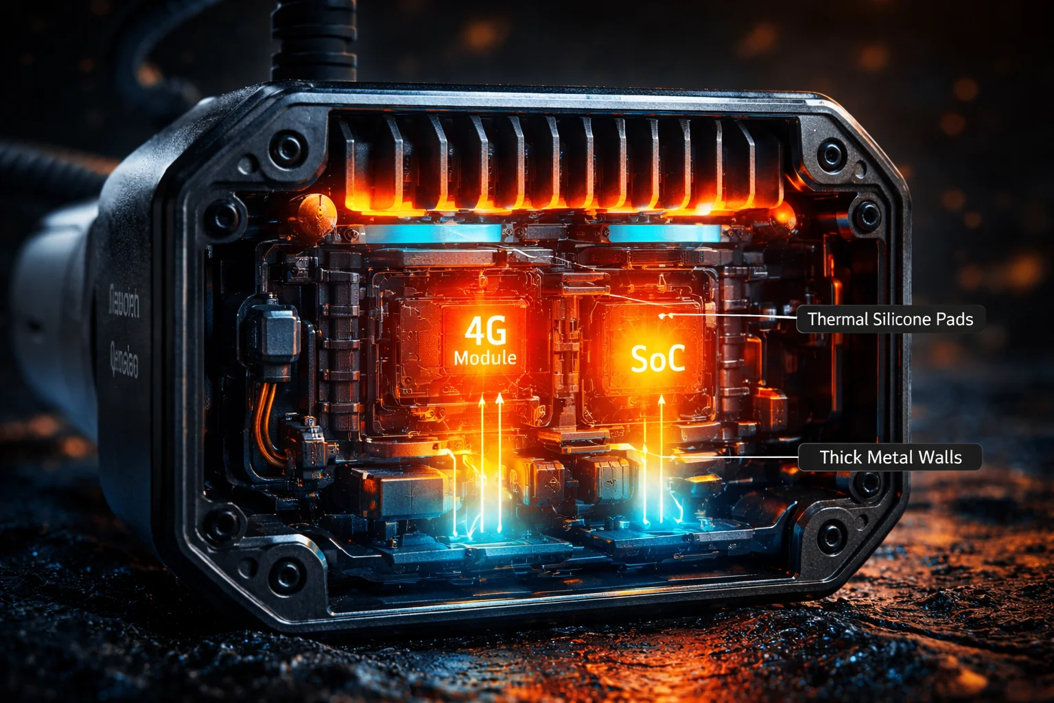
We manage 4G module heat through three layers: a full cast-aluminum housing that acts as a passive heatsink, internal thermal pads that bridge the 4G chipset to the metal shell, and firmware-based thermal throttling that reduces transmit power or encoding bitrate when the SoC temperature exceeds 85°C.
 thermal management 4G module 24/7 video uploading heat dissipation
The Real Heat Source Is Not the 4G Module Alone
Many people assume the 4G module is the hottest part. It is not. The 4K video SoC generates far more heat because it processes every frame before the 4G module even touches the data. In a typical design, the SoC runs at 70–80°C under full load, while the 4G module sits at 50–60°C. But they are often placed close together on the same PCB. Their combined heat creates a “thermal zone” that must be managed as one unit, not two separate problems.
Three-Layer Thermal Strategy
Layer 1: Cast-Aluminum Housing
The entire camera body is a heatsink. We use ADC12 die-cast aluminum with a wall thickness of 2.5–3 mm. The thermal conductivity of this alloy is about 96 W/m·K. The outer surface area of a typical PTZ dome is large enough to dissipate 15–20 W through natural convection alone, as long as there is some airflow around the housing. This is why mounting location matters. A camera bolted flat against a concrete wall with no gap will run 10–15°C hotter than one on a pole mount with open air on all sides.
Layer 2: Thermal Interface Materials
Between the chipset and the aluminum shell, we place silicone thermal pads 1 with a conductivity of 3–5 W/m·K. These pads fill the air gap and create a direct heat path from the chip to the metal. Without them, the air gap acts as an insulator, and the chip temperature can rise 20°C higher. We also use multi-layer copper pours on the PCB to spread heat across a wider area before it reaches the thermal pad.
Layer 3: Firmware Thermal Throttling
When the internal temperature sensor reads above 85°C, the firmware takes action. It can do one or more of the following:
- Drop the encoding frame rate from 25 fps to 15 fps.
- Lower the 4G transmit power by one step.
- Pause PTZ preset tours temporarily.
- Switch from 4K to 1080p encoding to cut SoC load.
This keeps the core temperature below 105°C, which is the absolute maximum for most industrial-grade chips. The camera does not shut down. It just runs a little lighter until the temperature drops back to a safe range.
Temperature Rise Data (ΔT)
Here is a reference table showing the temperature difference between the ambient air and the internal SoC under different conditions:
| Operating Mode | Ambient Temp | SoC Core Temp | ΔT (Rise) |
|---|---|---|---|
| Sleep Mode | 40°C | 42°C | +2°C |
| 4K Stream Only (No IR) | 40°C | 58°C | +18°C |
| 4K Stream + 4G Upload | 40°C | 65°C | +25°C |
| 4K + 4G + IR + PTZ | 40°C | 78°C | +38°C |
| 4K + 4G + IR + PTZ | 50°C (Texas sun) | 88°C | +38°C |
The last row is the critical one. At 50°C ambient (direct sun on a dark surface in Texas), the SoC hits 88°C. That is above the 85°C throttling threshold, so the firmware will step in. If you use a white housing or a sun shield, you can drop the effective ambient by 5–10°C and avoid throttling entirely.
Will the Camera Enter a “Sleep Mode” if the Battery Voltage Drops Below a Certain Level?
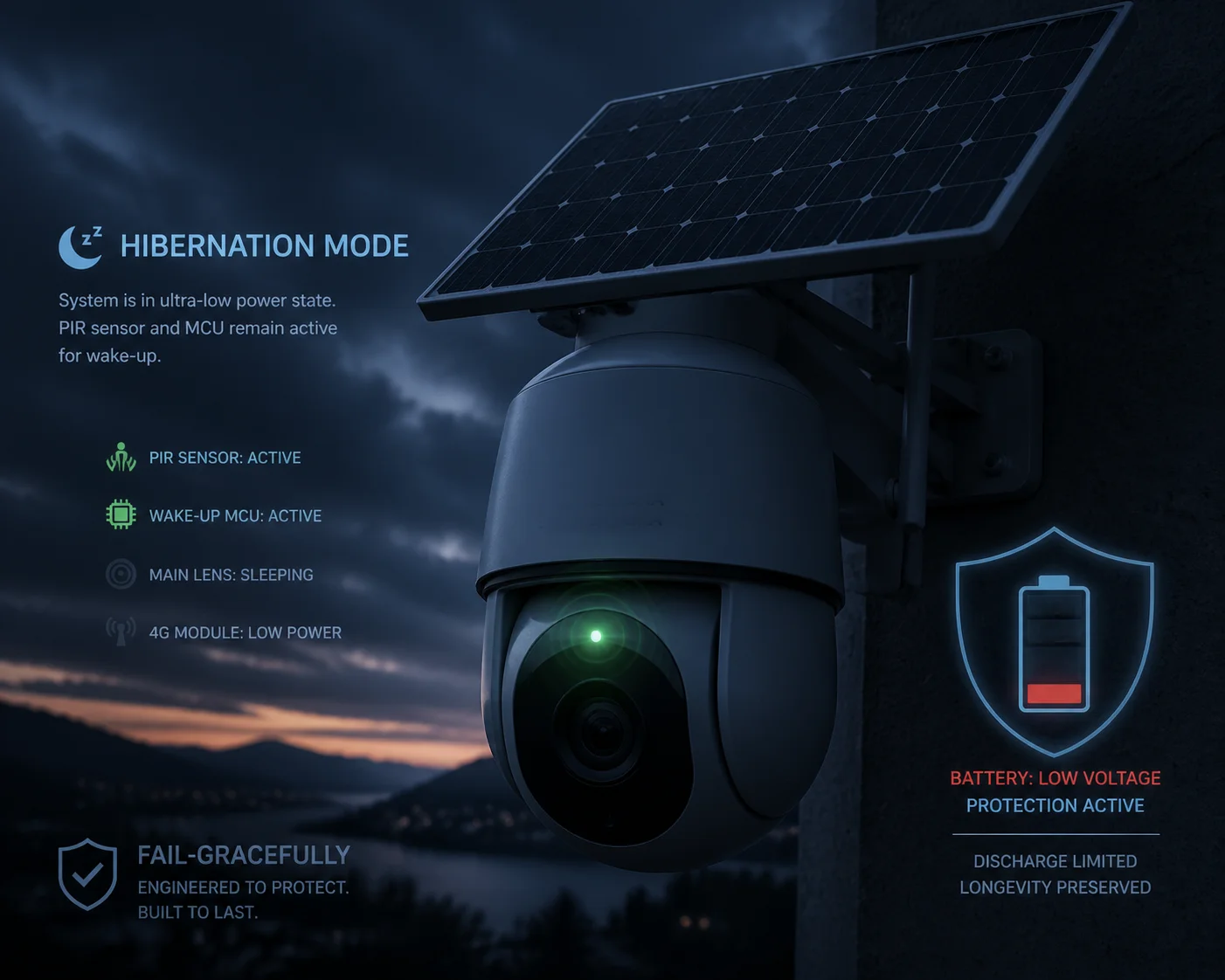
A dead camera is worse than no camera. I always tell integrators: your system must fail gracefully, not just go dark without warning.
Yes. Most low-power 4K 4G PTZ cameras have a configurable low-voltage cutoff. When the battery voltage drops below a set threshold — typically 11.0–11.5 V for a 12 V system — the camera enters deep sleep mode, drawing only 10–50 mW to keep the PIR sensor 2 and wake-up circuit alive.
 battery low voltage sleep mode 4G PTZ camera solar system
How the Sleep-Wake Cycle Works
The sleep mode is not just “off.” It is a carefully designed low-power state. The main SoC shuts down. The 4G module powers off. The IR LEDs turn off. The PTZ motors are de-energized. Only two things stay alive: the PIR (passive infrared) motion sensor and a tiny microcontroller that monitors battery voltage and the PIR signal.
When the PIR detects motion, it sends a wake-up signal to the main SoC. The SoC boots, initializes the 4G module, connects to the network, and starts recording. This entire wake-up process takes about 600 ms to 1 second in a well-designed system. Some cheaper designs take 3–5 seconds, which means you miss the first few seconds of the event. At Loyalty-Secu, we optimize the boot sequence to hit the 600 ms target consistently.
Voltage Thresholds and Hysteresis
The low-voltage cutoff is not a single number. It uses hysteresis to prevent rapid on-off cycling. Here is how it typically works:
- Sleep trigger: Battery voltage drops below 11.0 V for more than 10 seconds → camera enters deep sleep.
- Wake-up allowed: Battery voltage rises above 11.8 V for more than 30 seconds → camera is allowed to wake on PIR trigger.
- Full operation restored: Battery voltage stays above 12.2 V → camera returns to normal scheduled operation.
The gap between the sleep trigger (11.0 V) and the wake-up threshold (11.8 V) is the hysteresis band. Without this gap, the camera would bounce between sleep and active mode as the solar panel charges the battery just enough to cross the threshold, then the load pulls it back down.
What Happens Before Sleep
Before entering sleep, a good system sends a final status message over 4G. This message tells the cloud platform: “Battery low. Entering sleep. Last known voltage: 11.0 V. Estimated time to recovery: 4 hours (based on solar forecast).” This way, the monitoring center knows the camera is alive but conserving power. It is not a failure. It is a planned response.
Protecting Battery Longevity
Deep discharge kills lithium batteries fast. A LiFePO₄ 3 cell that is regularly discharged below 20% state of charge (SOC) will lose 30–40% of its cycle life compared to one that stays above 30% SOC. The low-voltage cutoff protects the battery, not just the camera. For a 12.8 V LiFePO₄ pack, we recommend setting the cutoff at 11.5 V, which corresponds to roughly 15–20% SOC. This gives you a safety margin while preserving the battery for 2,000+ charge cycles.
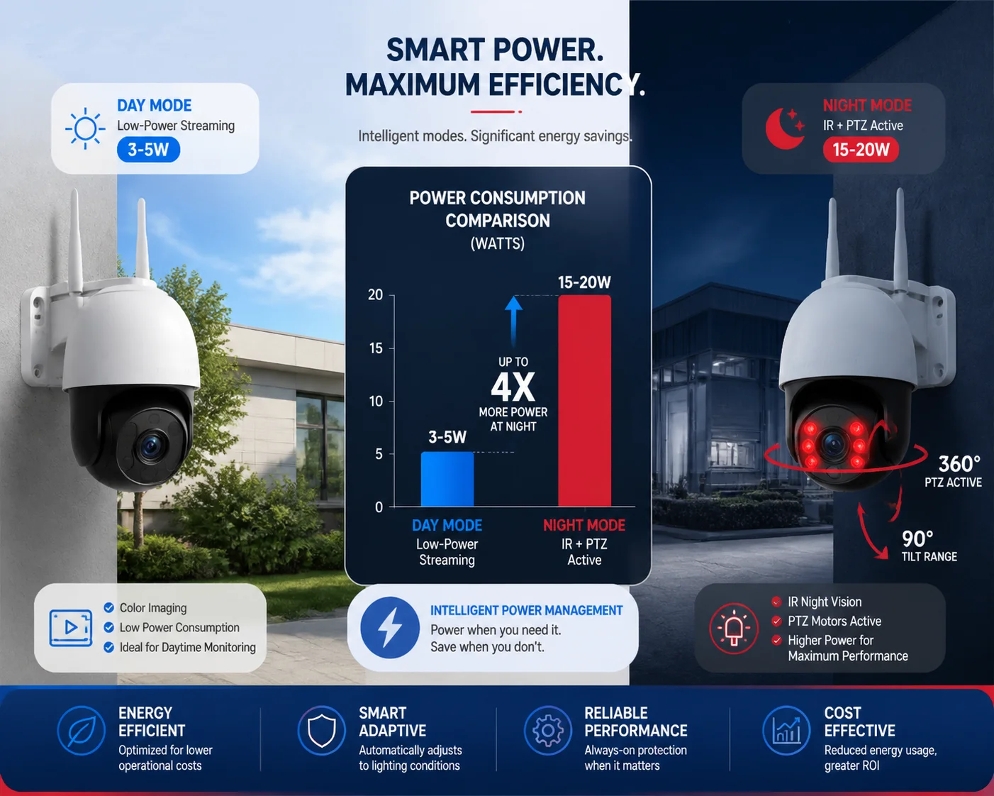
Can I See a Power Consumption Chart for Different Operating Modes (Day vs. Night)?
Every integrator I work with asks for this chart before they sign off on a solar design. Without it, you are guessing.
Here is a mode-by-mode power consumption breakdown for a typical low-power 4K 4G PTZ camera. Daytime streaming averages 3–5 W. Nighttime with IR active jumps to 8–12 W. Adding PTZ movement pushes the peak to 15–20 W. Deep sleep drops to 0.01–0.05 W.
 power consumption chart day vs night 4K 4G PTZ camera operating modes
The Full Power Chart
This table covers every operating mode you will encounter in a 24-hour cycle. I use this exact format when I spec systems for customers at Loyalty-Secu.
| Operating Mode | Power Draw | Duration (Typical 24h Cycle) | Daily Energy (Wh) | Notes |
|---|---|---|---|---|
| Deep Sleep (Hibernation) | 0.01 – 0.05 W | 10 – 16 hours | 0.1 – 0.8 Wh | PIR + heartbeat circuit only. |
| Daytime Standby (No Stream) | 0.5 – 1 W | 2 – 4 hours | 1 – 4 Wh | SoC on, no encoding, no 4G. |
| Daytime 4K Stream (4G) | 3 – 5 W | 2 – 4 hours | 6 – 20 Wh | H.265+ encoding + 4G upload. |
| Nighttime IR On (No PTZ) | 8 – 12 W | 2 – 4 hours | 16 – 48 Wh | IR array active, 4G streaming. |
| PTZ Active (Day or Night) | 15 – 20 W | 0.1 – 0.5 hours | 1.5 – 10 Wh | Motor bursts during tracking. |
| Estimated Daily Total | — | 24 hours | 25 – 83 Wh | Depends on event frequency. |
How to Read This Chart
The “Duration” column is the key variable. A camera on a quiet farm road might only stream for 30 minutes a day, triggered by a few vehicles. Its daily energy use could be as low as 10–15 Wh. A camera on a busy construction site entrance might stream 8 hours a day. That same camera now uses 60–80 Wh. Same hardware. Very different power budgets.
Sizing Your Solar System From This Data
Take the daily energy total and work backward:
- Daily energy need: Let’s say 50 Wh (moderate activity).
- Battery reserve: 3 days of autonomy (for cloudy weather) → 50 × 3 = 150 Wh.
- Battery size: For LiFePO₄ at 80% usable depth → 150 / 0.8 = 187 Wh → a 12.8 V / 15 Ah pack (192 Wh).
- Solar panel: In Texas, you get about 5 peak sun hours per day. To replenish 50 Wh plus 20% system losses → 60 Wh / 5 h = 12 W panel minimum. We recommend a 60–100 W panel to handle cloudy days and winter months.
Day vs. Night: The Real Gap
The biggest jump in power happens at sunset. The IR LEDs alone can add 5–10 W. If your site has frequent nighttime activity (wildlife, vehicles, trespassers), the night hours will dominate your power budget. One trick we use at Loyalty-Secu is to offer cameras with adjustable IR power. Instead of running all IR LEDs at 100%, the firmware can dim them to 50% when the target is close (under 30 meters). This cuts IR power from 7 W to 3.5 W and extends battery life significantly.
Another approach is to use a dual-sensor design: a low-power wide-angle lens for detection and the main 4K PTZ for verification. The wide-angle lens runs at 1 W continuously. It only wakes the 4K PTZ when it detects something worth recording. This “sentry mode” can cut daily energy use by 40–60% compared to running the 4K sensor around the clock.
Conclusion
Budget for 20 W peak, use aluminum housings for heat, and always ask your supplier for the ΔT test report and the low-voltage sleep threshold before you commit to a solar design.
1. Thermal pad conductivity for chip-to-heatsink heat transfer. ↩︎ 2. Passive infrared (PIR) sensor for low-power motion wake-up. ↩︎ 3. LiFePO₄ discharge depth and cycle life relationship. ↩︎ 4. ADC12 aluminum thermal conductivity and casting properties. ↩︎ 5. Natural convection vs forced convection in sealed housings. ↩︎ 6. Hysteresis band design for low-voltage solar cutoffs. ↩︎ 7. IR LED dimming for adjustable night illumination power. ↩︎ 8. Dual-sensor sentry mode power savings calculation. ↩︎ 9. H.265 encoding power consumption vs frame rate. ↩︎ 10. C-rate discharge limits for LiFePO₄ in solar systems. ↩︎