
I have seen many projects fail at night because the camera starts well, but the power path cannot handle the first surge. That small gap can turn into a big reset.
The peak current for an 800m laser PTZ during nighttime startup is usually around 5A to 6A at 24V DC, and it can be much higher at 12V DC. This surge comes from the laser module, PTZ motors, cooling parts, and the core board starting at the same time.
 800m laser PTZ nighttime startup peak current
When I plan a solar or battery system for this kind of camera, I always look at peak load first. The average current does not protect the system if the startup surge is too strong.
Table of Contents
Can your lithium battery handle the 5A+ peak surge when the laser and PTZ motors move simultaneously?
I have seen a battery look strong on paper, but still fail when the camera wakes up at night. The problem is not only capacity. It is also discharge speed.
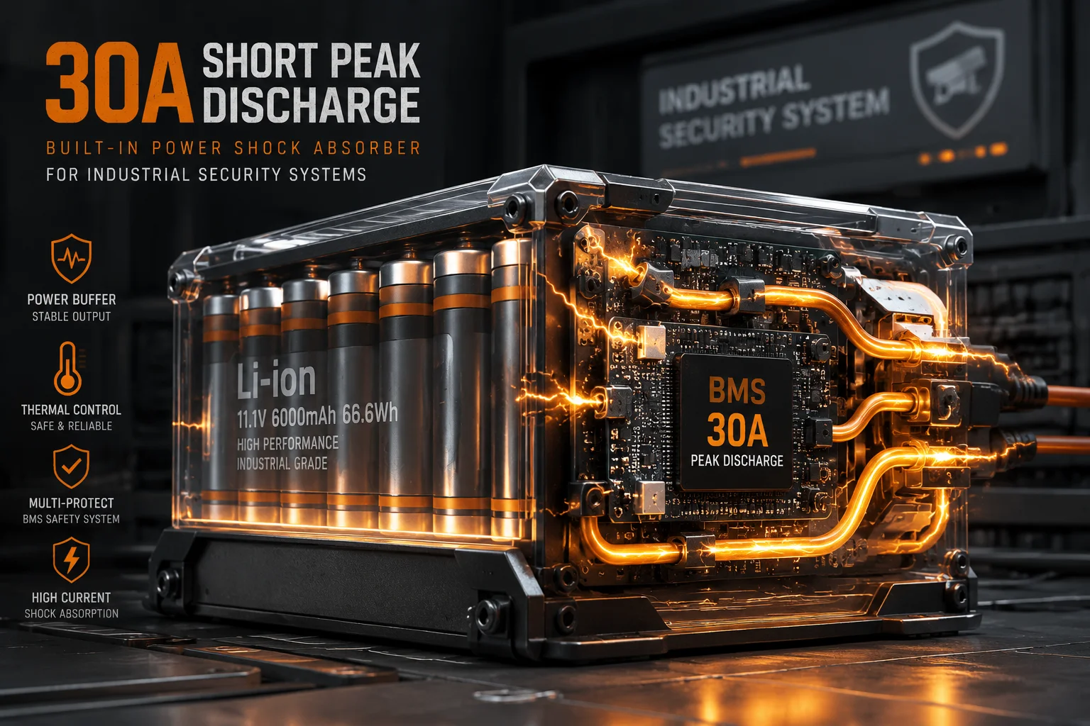
A lithium battery3 can handle this peak surge only if its BMS, cells, and wiring are built for high output. For an 800m laser PTZ, I would want at least 15A continuous discharge and 30A short peak discharge at 24V system design.
 lithium battery peak surge for PTZ startup
I treat the battery like a shock absorber. The camera does not draw power in a smooth way at startup. It pulls hard for a short time, and that short pull can be the real test. The laser module1 may ask for 2.5A to 3.5A by itself. The PTZ motors2 may add 1.5A to 2.0A more. Then the fan or heater can add another 0.5A to 1.0A. The board and 4G module still need steady power. So I do not trust rated capacity alone. I ask if the battery can keep voltage stable when all of these loads hit at once. I also check the cable length, cable size, and connector loss. A good battery can still fail if the wires are thin or too long. For field jobs, I prefer high-rate lithium cells because they recover fast and hold voltage better under stress. I also make sure the BMS4 does not cut off too early. If the BMS sees a spike and shuts down, the whole system can reboot. That is why I always test the real startup draw on site, not just in a lab.
Will a sudden peak current draw cause a “Voltage Dip” that triggers a 4G modem reset?
I have watched a 4G modem6 go offline for one simple reason: the camera asked for too much power in one second. That kind of failure is annoying because the modem is not broken. It just lost clean voltage.
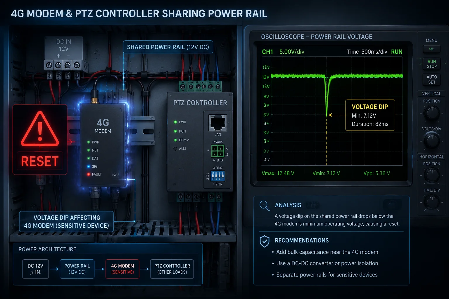
Yes, a sudden peak current draw can create a voltage dip5, and that dip can reset a 4G modem. The modem is often the first part to fail because it is sensitive to power noise and short drops.
 voltage dip causing 4G modem reset
Why the modem fails first
I see three common reasons:
| Problem | What happens | Result |
|---|---|---|
| Power line drop | Current rises fast, and voltage falls on the cable | The modem loses stable input |
| Shared load spike | Laser and PTZ motors start with the modem at the same time | The modem resets or reboots |
| Weak power buffer | No capacitor bank or small buffer on the PCB | Short surge reaches the modem directly |
I often explain this to customers in a simple way. The modem is like a person trying to read in a room while the lights blink on and off. It may not crash every time, but it becomes unstable. In real sites, the problem gets worse when the power cable is long, the battery is low, or the DC-DC stage7 has poor response. I also check the modem’s own input range. Some 4G modules can survive a wide range, but they still dislike fast dips. If the system uses a shared 24V rail, the best fix is not only a bigger battery. I also want better local buffering near the modem and board. A low-ESR capacitor11 bank can help cover the short gap before the battery or converter reacts. I also like soft-start logic8. If the laser starts after the PTZ self-check, the whole load spike gets spread out. That simple delay can save many field calls.
Does the system use high-discharge “C-Rate” cells to accommodate long-range laser illumination?
I always ask about C-rate when I review a long-range solar PTZ system. If the cells cannot deliver current fast enough, the whole design looks good only on paper.
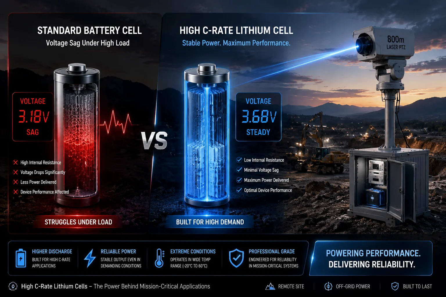
Yes, a system like this should use high-discharge cells with a strong C-rate9. Long-range laser illumination needs fast current delivery, not just large capacity. A low-rate cell may hold enough energy, but it may still sag under startup load.
 high-discharge C-rate cells for laser PTZ
What C-rate means in real use
I keep the idea simple:
| Cell type | Good point | Risk |
|---|---|---|
| Low-discharge cell | Strong energy storage | Voltage sag under surge |
| High-discharge cell | Fast current output | Often higher cost |
| Weak BMS setup | Easy to build | May trip at startup |
For an 800m laser PTZ, I want cells that can handle both steady work and short surge. The reason is clear. The laser module needs a strong pulse when it turns on. The motors also need extra torque at the same time. If the battery chemistry is too soft, the voltage drops fast. That drop can hurt the PTZ board, the 4G modem, and even the image module. I also think about heat. High-discharge cells often work better when the system has good thermal control. If the battery is in a hot box, the safe current window gets smaller. So I do not look at C-rate alone. I also check pack design, cell balance, BMS current limit, and wire loss. In many off-grid projects12, I suggest a battery pack that gives more current headroom than the spec sheet seems to need. That extra room reduces stress and gives the system a longer life. I would rather build with margin than explain another night reboot to a client.
Is there a large capacitor bank on the PCB to buffer the instantaneous current load?
I have found that many power issues are not caused by the battery. They are caused by the few milliseconds before the battery response reaches the board. That is where a capacitor bank helps.
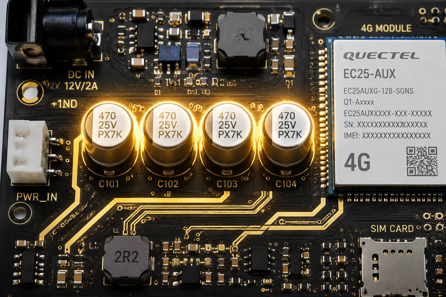
Yes, a good PCB often uses a capacitor bank10 to buffer the instant load. It cannot replace the battery, but it can smooth the first sharp current hit and protect the board from fast dips.
 capacitor bank on PCB for instantaneous current load
How local buffering helps
I use local buffering for three reasons:
- It supports the board during the first surge.
- It reduces voltage ripple near sensitive chips.
- It gives the DC-DC circuit a short bridge time.
A simple check list for field design
| Item | What I check | Why it matters |
|---|---|---|
| Capacitor bank size | Enough bulk capacitance near load | Helps absorb instant surge |
| ESR value | Low ESR preferred | Reduces heat and loss |
| PCB layout | Short power path | Lowers resistance and drop |
| Converter response | Fast transient response | Keeps voltage stable |
I do not treat the capacitor bank as a magic fix. It only works well when the whole power chain is clean. If the cable is too thin, the connector is weak, or the DC-DC module is undersized, the capacitor bank will only delay the problem. But it still matters a lot. In real camera systems, startup happens in a short burst. The laser wakes up. The PTZ moves. The fan starts. The modem waits for stable power. That is a hard moment for any board. A good buffer can prevent a small dip from becoming a full reset. I also like to place the buffer close to the modem and the control board, not far away on another part of the PCB. Distance adds loss. In my experience, good local design often solves problems that people first blame on firmware.
Conclusion
I always design for peak current first, because startup stress decides whether an 800m laser PTZ runs stable or resets at night.
1. Learn how laser diodes draw high inrush current during startup. ↩︎ 2. Explore starting torque and current draw of PTZ motors. ↩︎ 3. Understand lithium battery chemistry and discharge characteristics. ↩︎ 4. Learn how Battery Management Systems protect against surge conditions. ↩︎ 5. Definition and effects of voltage dips on sensitive electronics. ↩︎ 6. Typical power supply requirements for 4G modules. ↩︎ 7. Learn how DC-DC converters handle transient loads. ↩︎ 8. How soft-start spreads inrush current over time. ↩︎ 9. Definition and importance of C-rate for high discharge applications. ↩︎ 10. How capacitor banks provide local energy buffering. ↩︎ 11. Benefits of low equivalent series resistance in transient response. ↩︎ 12. Best practices for off‑grid power system design. ↩︎