
I have seen too many customers throw away an entire mainboard because lightning burned one Ethernet port. That single failure costs hundreds of dollars and hours of painful downtime.
A split SoC and I/O board architecture isolates faults, cuts repair costs, extends hardware lifespan through better thermal management, and allows processor upgrades without replacing the full system. This modular design turns expensive whole-board replacements into quick, low-cost module swaps that any field technician can handle.
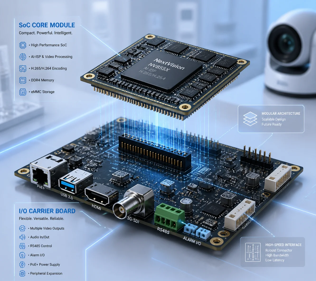 split SoC and IO board architecture PTZ camera maintenance benefits
Below, I break down the four biggest maintenance wins this architecture gives you. Whether you care about processor upgrades, faster field repairs, thermal performance during 4K 4G streaming, or spare-part costs, each section answers a real question I hear from integrators every week. Let’s get into it.
Table of Contents
Can I upgrade the main processor without replacing the entire I/O and motor drive?
I have watched customers panic when their SoC chip hits end-of-life. On a single-board design, that means scrapping everything — even the perfectly good motor driver and every cable connected to it.
Yes. With a split architecture, the SoC core board plugs into the I/O carrier board through a standard connector. You can swap the core board for a newer, more powerful version while the I/O board, motor drive, and all wiring stay exactly where they are.
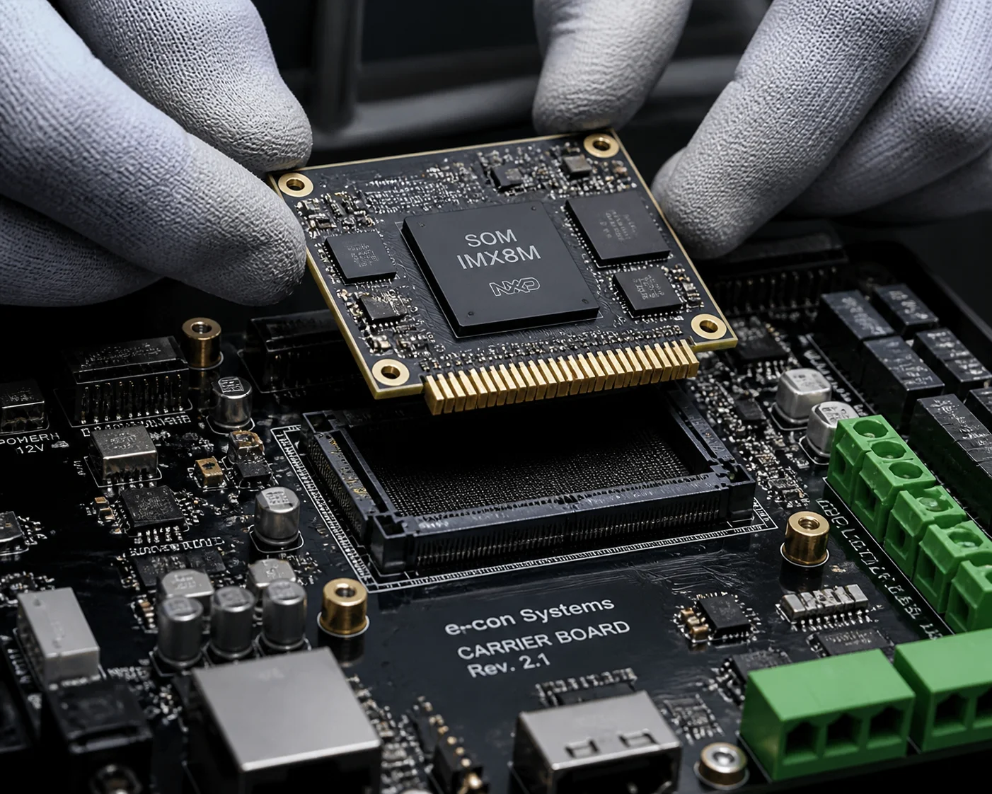 upgrade SoC core board without replacing IO board PTZ camera
Why SoC Chips Die Before I/O Boards
In the embedded world, a SoC chip, DDR memory, and eMMC storage typically have a commercial life of five to seven years. After that, the chip maker stops production. But the parts on an I/O board — power regulators, terminal blocks, RS485 transceivers, relay drivers — are commodity components. They stay available for fifteen or even twenty years.
When you put both groups on one PCB, the short-lived SoC drags the long-lived I/O parts into the grave with it. I think that is a waste of money and engineering effort.
A split design fixes this by treating the core board like a replaceable brain. The I/O carrier board is the body. When the brain gets old, you give it a new one. The body keeps working.
What a Real Upgrade Path Looks Like
Here is a common scenario I see with our PTZ customers. A system integrator deployed 200 cameras five years ago. The original SoC handles H.265 encoding fine, but the customer now wants on-edge AI analytics — face detection, vehicle tracking, hard-hat recognition. The old NPU is too weak.
With a split board design, the upgrade plan is simple:
- The factory designs a new core board with a stronger NPU. The connector footprint and pin assignment stay the same.
- The integrator orders 200 new core boards. Each one costs a fraction of a full mainboard.
- A local technician opens the housing, unplugs the old core board, plugs in the new one, and closes it up. No rewiring. No re-aiming the camera. No touching the pan-tilt motor.
- The I/O board detects the new core board on boot. Firmware loads automatically. The camera is back online in minutes.
This is the same SoM (System on Module) plus carrier board model 1 that the wider embedded industry already uses. It works.
Upgrade Cost: Split vs. Single Board
| Cost Factor | Split Architecture | Single-Board Design |
|---|---|---|
| Component replaced | Core board only (SoC + DDR + eMMC) | Entire mainboard |
| Typical unit cost | 30–40% of full board price | 100% of full board price |
| Field labor time | 10–15 minutes per camera | 45–90 minutes (full disassembly) |
| Re-calibration needed | No | Often yes (motor connectors disturbed) |
| Software re-configuration | Minimal (I/O drivers unchanged) | Full (new board, new MAC, new config) |
The bottom line: you protect your existing investment in housings, brackets, cables, and I/O logic. You only pay for the new brain.
How does the modular design simplify field repairs for my technicians?
I get calls from integrators who send a technician two hours into the desert, only to find out the guy brought the wrong replacement board. With a single-board design, there is only one board — and it is expensive, fragile, and hard to diagnose.
A modular split design gives your technician a clear fault boundary. If the video freezes, swap the core board. If the network port is dead, swap the I/O board. This “replace and test” method cuts diagnosis time from hours to minutes and needs no advanced engineering skill.
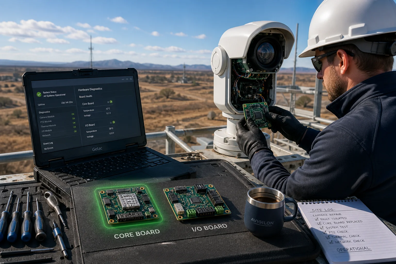 modular PTZ camera field repair split board design
The “Swap and Check” Method
In industrial maintenance, the fastest way to find a fault is to replace one module at a time. A split architecture gives you a natural break point. Here is how I train field teams to use it:
Step 1: Connect a laptop to the core board’s UART debug port. Check if the Linux system boots. If it does not boot, the core board is dead. Replace it.
Step 2: If the system boots fine but the network has no link, or the PTZ motor does not move, the problem is on the I/O board side. Swap the I/O board.
Step 3: If both boards test good individually, check the connector between them and the cable harness.
This three-step process works for any technician who can use a screwdriver and read a serial console. No oscilloscope. No soldering. No phone call to the factory at 3 AM.
Why This Matters for Remote Sites
Many of my customers install PTZ cameras on cell towers, oil pipelines, highway poles, and solar farms. These sites are far from any workshop. The cost of sending a skilled engineer is often three to five times the cost of the hardware itself.
With a single-board camera, the technician must bring the entire mainboard. If the real problem turns out to be a burned power input trace, he still has to swap the whole board. And he has to reconfigure every setting afterward.
With a split design, he carries one core board and one I/O board in his bag. He tests on-site, swaps only what is broken, and drives home. The camera is back online before his boss finishes lunch.
Fault Type vs. Board Replaced
| Fault Symptom | Most Likely Cause | Board to Replace |
|---|---|---|
| Video freeze / system crash | SoC hang or DDR failure | Core board |
| No boot / eMMC corrupt | Storage failure on core board | Core board |
| Ethernet port dead | Surge damage to PHY chip on I/O board | I/O board |
| PTZ motor not responding | Motor driver IC failure or RS485 burn | I/O board |
| 4G module no signal | SIM slot or RF path damage on I/O board | I/O board |
| Image OK but no AI detection | NPU too weak or firmware issue | Core board (upgrade) |
This table is what I give to every new customer. Print it, laminate it, and put it in your technician’s toolbox. It saves time and money.
For more on field diagnostics, see this guide to troubleshooting embedded surveillance systems 2.
Does separating the boards help with heat dissipation during 4K 4G transmission?
I have tested single-board PTZ cameras that shut down after two hours of continuous 4K streaming over 4G in a sealed housing at 55°C ambient. The SoC was cooking the 4G module right next to it. Both failed together.
Yes. Physically separating the SoC from the I/O board creates two independent thermal zones. The high-heat SoC gets its own heat sink and airflow path, while temperature-sensitive components like 4G modules, electrolytic capacitors, and motor drivers stay cooler. This thermal decoupling directly increases the mean time between failures (MTBF) of every component on the I/O board.
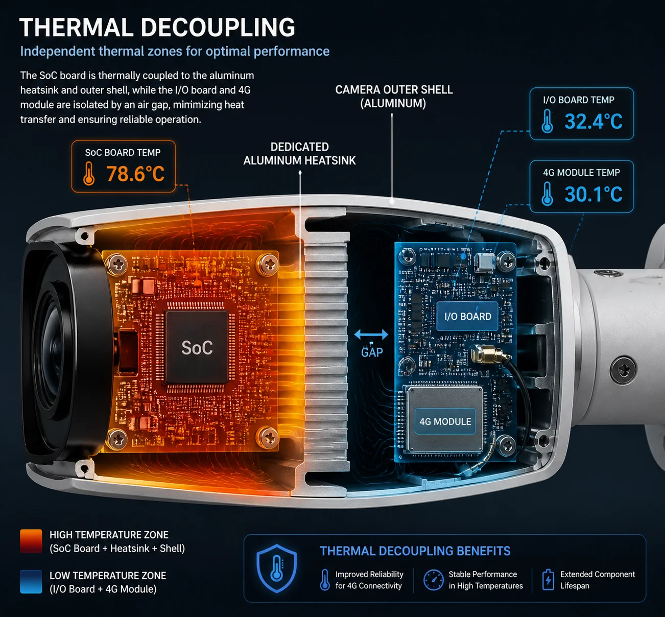 thermal decoupling split board 4K PTZ camera heat dissipation
Where the Heat Comes From
A modern PTZ camera SoC doing 4K H.265 encoding at 30fps with 120dB WDR can pull 4 to 6 watts of power. Almost all of that turns into heat. When you add a 4G LTE module transmitting a continuous video stream, the module itself adds another 2 to 3 watts of heat.
On a single board, these two heat sources sit 10 to 20 millimeters apart. The hot air from the SoC heatsink rises directly onto the 4G module. The 4G module’s RF performance drops as temperature rises. At some point, the modem throttles its data rate or disconnects entirely. Your customer sees a frozen video feed and calls you.
How Thermal Decoupling Works in Practice
In our split design, the SoC core board mounts on one side of the internal frame. It has its own aluminum heatsink that contacts the metal housing. Heat flows from the SoC, through the heatsink, and out through the housing wall.
The I/O board sits on the other side. The 4G module, the PoE circuit, the motor driver, and all the connectors live here. They get natural airflow from the opposite direction. There is a physical gap — usually 15 to 30 millimeters of air — between the two boards.
This gap acts like a firewall for heat. The I/O board stays 10 to 15 degrees cooler than it would on a single-board layout. That temperature drop is not small. Every 10°C reduction in operating temperature roughly doubles the life of an electrolytic capacitor. It also keeps the 4G module in its comfortable operating range, so you get stable uplink speeds even on a hot summer afternoon.
Learn more about thermal management in embedded camera design 3.
The Maintenance Payoff
From a maintenance point of view, cooler components last longer. Longer-lasting components mean fewer truck rolls. Fewer truck rolls mean lower OPEX for your projects. I have seen customers cut their annual field-failure rate by 30 to 40 percent just by switching from a single-board camera to a split-board camera in high-temperature environments.
The math is simple. If a truck roll costs you $500 and you avoid 20 trips per year across a 200-camera deployment, you save $10,000 a year. That pays for the cameras themselves within the first warranty period.
For reference, review this arrhenius equation guide to temperature and component lifespan 4.
Will this architecture reduce the cost of keeping spare parts in my local warehouse?
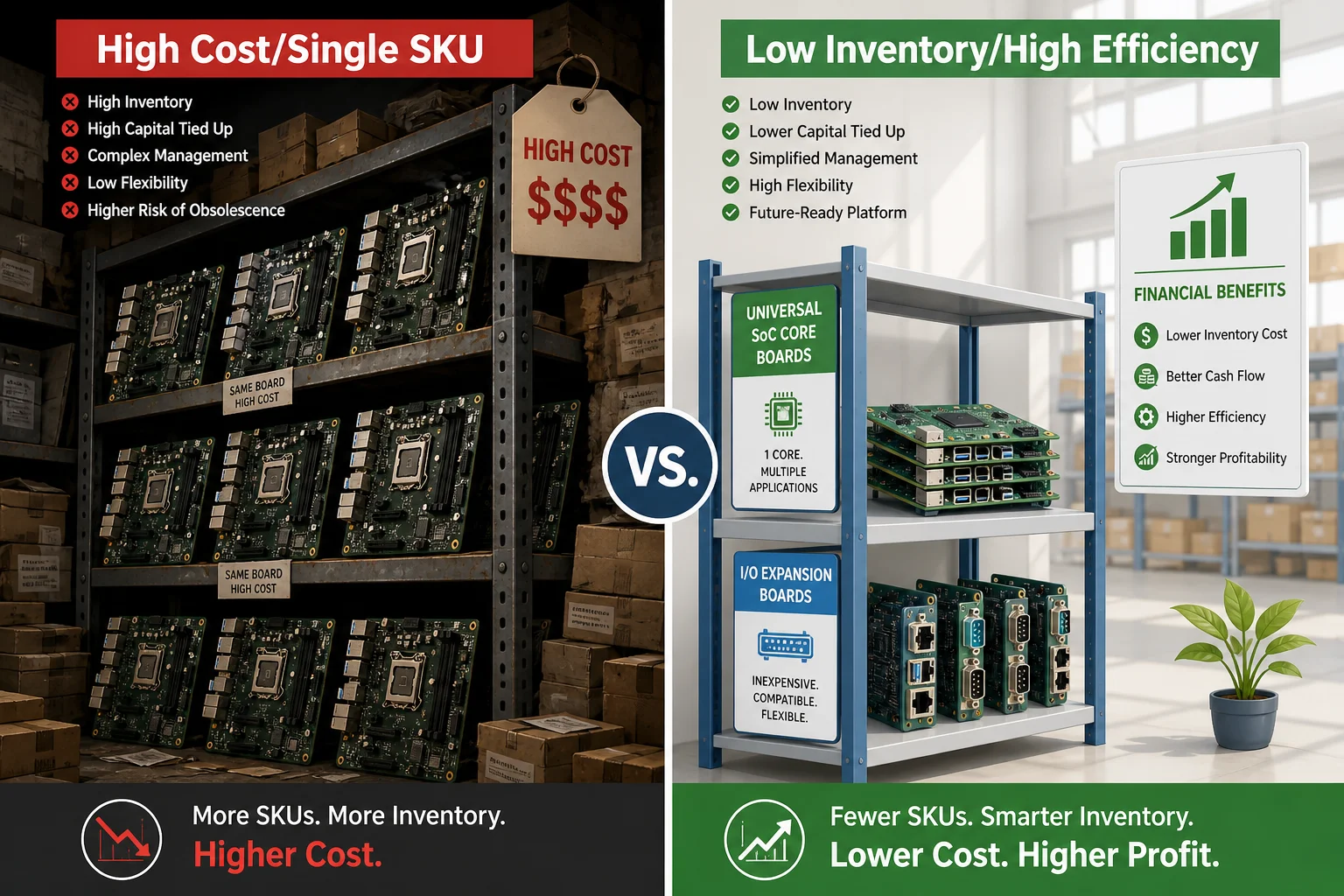
I know integrators who keep a shelf full of expensive mainboards — one SKU per camera model. Every new project adds another SKU. The warehouse bill grows, but most of those boards never get used before they become obsolete.
Yes. A split architecture sharply reduces spare-part variety and cost. You stock a small number of core boards and a set of common I/O boards. Because one core board model can work across many camera models, your total inventory shrinks. You spend less money sitting on shelves and more money earning returns on active projects.
 spare parts warehouse split board PTZ camera inventory
The Inventory Math
Think about a typical integrator who sells five different PTZ camera models. In a single-board world, that means five different mainboard SKUs in the spare-parts bin. Each board costs $80 to $150. To keep two spares per model, you hold $800 to $1,500 in inventory just for mainboards.
Now switch to a split design. All five camera models use the same core board. The I/O boards differ because each model has different connectors and interfaces. But I/O boards are cheap — $15 to $30 each — because they carry no expensive SoC, no DDR memory, and no eMMC storage.
Your new inventory looks like this: two core boards (covers all five models) plus two I/O boards per model (ten boards total). The core boards carry most of the cost, but you only need two instead of ten. The I/O boards are cheap. Your total inventory cost drops by 40 to 60 percent.
Cross-Project Compatibility
Here is another angle that saves money. When you standardize on one core board across projects, your software stack also stays standard. The same firmware image, the same SDK, the same debug tools work everywhere. Your technician does not need to remember which firmware goes on which board. He grabs a core board, plugs it in, and the system auto-detects the I/O board type.
This means fewer mistakes in the field. Fewer mistakes mean fewer repeat visits. Fewer repeat visits mean lower cost.
Spare Parts Strategy: Split vs. Single Board
| Inventory Item | Split Architecture | Single-Board Design |
|---|---|---|
| SKUs to stock | 1–2 core boards + a few I/O board variants | One unique mainboard per camera model |
| Cost per spare core board | $50–$80 | N/A (no separate core board exists) |
| Cost per spare I/O board | $15–$30 | N/A |
| Cost per spare mainboard | N/A | $80–$150 |
| Total inventory for 5 models (2 spares each) | ~$250–$500 | ~$800–$1,500 |
| Obsolescence risk | Low (only core board tracks SoC lifecycle) | High (entire board becomes obsolete with SoC) |
What to Ask Your Supplier
If you are buying PTZ cameras from a Chinese manufacturer and you want these inventory benefits, put it in your purchase agreement. Here is what I recommend:
- The core processing board (SoC + DDR + eMMC + PMIC) must use a modular, plug-in design with a standard high-reliability connector.
- The I/O carrier board must include all external interfaces, power input, PTZ motor drive, and supplemental lighting control. It must support at least two generations of compatible core boards.
- The supplier must offer the core board as a standalone spare part with its own part number and a replacement guide.
- When the current core board reaches end-of-life, the supplier must provide a pin-compatible and dimension-compatible upgrade version that works on the existing I/O board without hardware modification.
These are standard practices in the embedded SoM industry. Any serious R&D-driven manufacturer should be able to meet them. If your supplier cannot, that tells you something about their engineering depth.
For further reading on modular hardware design benefits, see this whitepaper on System on Module standardization 5 and this guide to reducing MTTR (Mean Time To Repair) 6.
Conclusion
A split SoC and I/O board architecture lowers repair costs, speeds up field diagnosis, improves thermal reliability, and simplifies spare-part management — every maintenance advantage a serious integrator needs.
1. Introduction to System on Module (SoM) architecture. ↩︎ 2. Embedded systems troubleshooting guide for field technicians. ↩︎ 3. Thermal design strategies for embedded vision systems. ↩︎ 4. Arrhenius equation and thermal acceleration of component aging. ↩︎ 5. SGET standards for System on Module form factors. ↩︎ 6. How modular design improves Mean Time To Repair (MTTR). ↩︎