
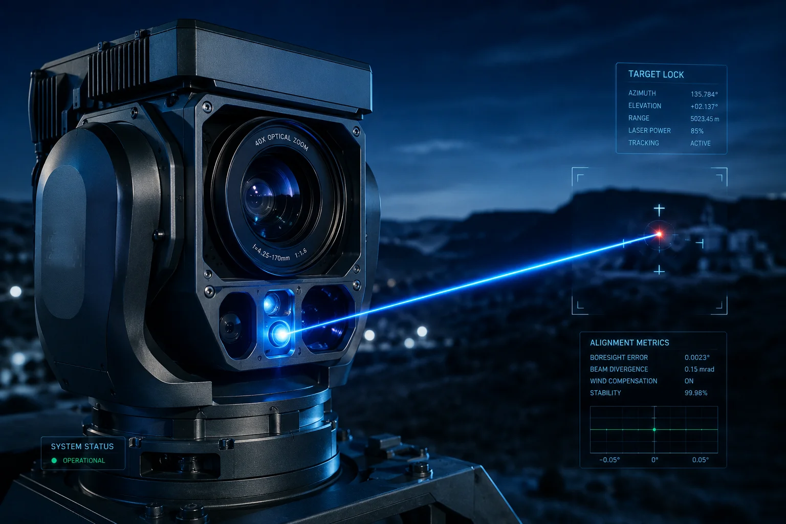
I once lost a $12,000 contract because my laser night vision camera couldn’t keep its beam centered at 40X zoom. The client saw a dark target and a bright sidewalk. That was the day I learned how critical laser-lens alignment really is.
The laser spot stays centered through a three-layer system: a synchronized stepper motor adjusts the beam angle during zoom, a scheduled self-calibration corrects physical drift every 24 hours, and a real-time AI closed-loop keeps the spot locked on target during active tracking.
 laser spot alignment PTZ camera zoom compensation
Below, I’ll break down each layer of this alignment system. I’ll explain the mechanical side, the software side, and what happens when things go wrong at maximum speed or under heavy vibration. If you deploy PTZ cameras in remote, off-grid locations like many of our clients do, this matters more than you think.
Table of Contents
Does the “Laser-Lens Sync” Algorithm Use Mechanical or Software-Based Center Alignment?
I used to think it was one or the other. Either you bolt the laser to the lens and hope for the best, or you fix everything in software. The truth is neither approach works alone.
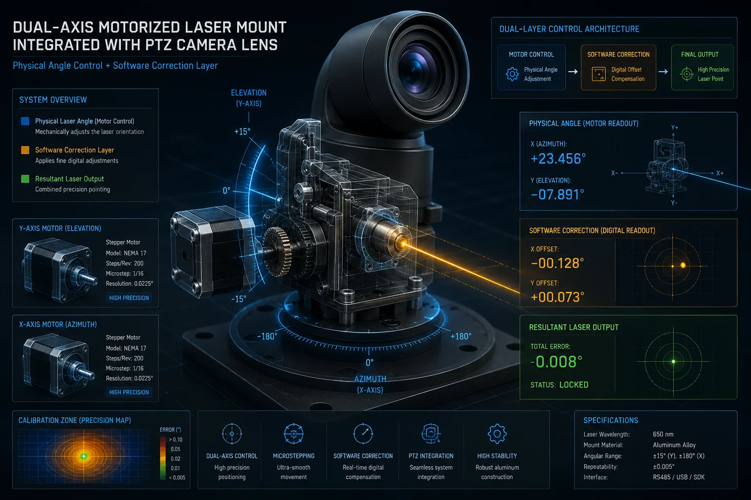
The system uses both. A stepper motor1 physically moves the laser beam to match the zoom level, while software applies a stored offset value to correct any remaining drift. This dual approach keeps alignment within 0.1 degrees at all focal lengths.
 laser lens sync mechanical software alignment
Why Mechanical Alone Fails
A fixed-mount laser works fine at low zoom. At 5X or 10X, the field of view is wide enough that a small misalignment doesn’t matter. But at 40X, the field of view2 shrinks to about 1.5 degrees. At that magnification, even a 0.05-degree offset pushes the laser spot dozens of meters away from the image center at 500 meters distance.
This is basic geometry. The farther the target, the bigger the error. A purely mechanical mount cannot maintain perfect alignment across the full zoom range because:
- Thermal expansion3 changes metal dimensions by micrometers
- Gravity pulls differently at different tilt angles
- Bearing wear introduces play over thousands of cycles
How the Stepper Motor Works
The laser module sits on a micro dual-axis motorized platform. This platform is linked to the zoom motor through the camera’s SoC (System on Chip). Inside the SoC, there is a pre-loaded lookup table4. This table maps every zoom position to a specific laser beam angle and beam width.
When you zoom from 10X to 40X, the stepper motor does two things at once:
- It adjusts the beam expander lens to narrow the laser spot diameter
- It tilts the laser axis to compensate for the changing optical center
How Software Fills the Gap
After the motor does its job, there is always a small residual error. The software layer handles this. During factory calibration, the system measures the offset at multiple zoom positions and stores these values in NVRAM5 (non-volatile memory). Every time the camera zooms, it reads the stored offset for that focal length and adds it to the motor command.
| Alignment Layer | What It Corrects | Precision Level |
|---|---|---|
| Stepper motor | Beam angle and spot size vs. zoom level | ±0.3° |
| Software offset (factory) | Residual mechanical tolerance | ±0.1° |
| AI closed-loop (runtime) | Dynamic drift from wind, vibration, wear | < 0.05° |
This layered approach means no single point of failure can break the alignment. If the motor is slightly off, software catches it. If software values drift over time, the AI loop corrects in real time.
Will the Laser Beam Become “Off-Center” if the PTZ Moves at Its Maximum Rotation Speed?
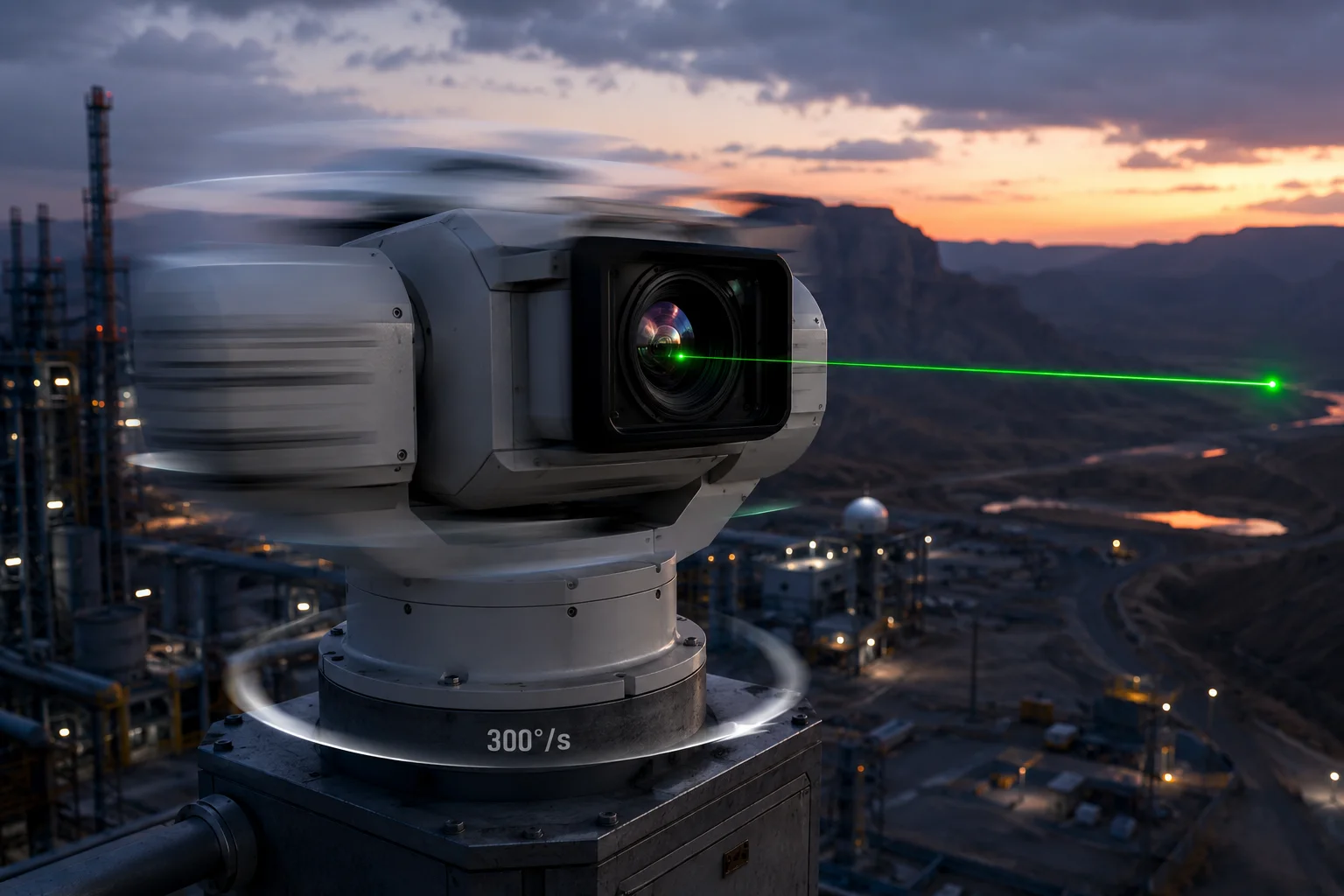
I tested this myself during a factory visit. We spun the PTZ at full speed — 300 degrees per second — and watched the laser. It lagged. Not by much, but enough to notice on a 40X zoomed image.
Yes, at maximum rotation speed, the laser will briefly fall off-center. The stepper motor has a response delay of 20-50 milliseconds. However, the system uses predictive pre-compensation6 to minimize this lag, and the AI loop corrects any residual offset within 100 milliseconds of the PTZ stopping.
 PTZ maximum speed laser offset compensation
Understanding the Physics of Lag
When a PTZ head rotates at 300°/s, it covers 6 degrees in just 20 milliseconds. The laser stepper motor cannot physically respond that fast. Its maximum slew rate is typically around 200°/s. So during rapid pan or tilt movements, the laser will trail behind the optical axis.
But here’s the key insight: this doesn’t matter as much as you’d think. When the PTZ is spinning at full speed, the image is a motion blur. No useful surveillance is happening during that transit. What matters is how fast the laser re-centers after the PTZ reaches its target position.
Predictive Pre-Compensation
The camera’s firmware knows where the PTZ is going before it arrives. When you click a preset position or when the AI tracker sends a move command, the system calculates the trajectory in advance. It then sends the laser motor a “lead” command — telling it to start moving slightly before the PTZ head does.
This is similar to how a rifle scope’s ballistic calculator leads a moving target. The laser doesn’t chase the PTZ. It anticipates where the PTZ will stop.
Recovery Time After Fast Movement
| PTZ Speed | Laser Lag During Move | Recovery Time After Stop | Visible Impact at 40X |
|---|---|---|---|
| Slow (30°/s) | < 5ms | Instant | None |
| Medium (120°/s) | 10-20ms | < 50ms | Barely visible |
| Maximum (300°/s) | 30-50ms | 50-100ms | Brief flash off-center |
For David and other system integrators, the practical takeaway is this: if your use case involves smooth AI tracking (which moves at 30-60°/s), the laser stays perfectly centered at all times. The lag only appears during manual joystick slewing at full speed, and it self-corrects almost instantly.
What About Continuous Patrol Mode?
During automated patrol routes, the PTZ moves at controlled speeds — usually 20-60°/s between presets. At these speeds, the stepper motor keeps up without any visible offset. The system also pauses briefly at each preset position, giving the self-calibration routine a chance to verify alignment before the camera begins recording at that angle.
Can I Manually Calibrate the Laser Spot’s Position Through the Camera’s Web Backend?
I’ve had clients ask me this after receiving units that shipped across the Pacific in a container. Rough handling during transit can knock the laser axis off by a fraction of a degree. The answer is yes, and it takes about two minutes.
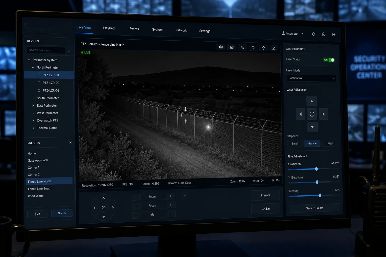
Yes. The camera’s web interface includes a laser calibration page where you can manually adjust the horizontal and vertical offset of the laser spot. You move the spot using arrow keys or slider controls until it aligns with the crosshair on the live video feed.
 manual laser calibration web interface PTZ camera
Accessing the Calibration Menu
In most of our firmware builds, the laser calibration page sits under Settings > PTZ > Laser Alignment. You’ll see a live video feed with a crosshair overlay at the center. Below the video, there are four directional buttons (up, down, left, right) and a step-size selector (coarse or fine).
Step-by-Step Manual Calibration
Here’s how a technician typically performs this:
- Point the camera at a flat, dark surface at least 50 meters away
- Set the zoom to maximum (40X)
- Turn on the laser at full power
- Look at where the bright spot appears relative to the crosshair
- Use the arrow controls to nudge the laser until the spot centers on the crosshair
- Save the calibration values
- Zoom out to 1X and verify the spot still covers the full field of view
Why Manual Calibration Still Matters
Even though the system has automatic self-calibration, there are situations where manual intervention is better:
- After physical impact: If the camera was hit or dropped, the auto-calibration might not run until the next scheduled cycle. Manual calibration gives you immediate correction.
- Custom installations: Some mounting brackets introduce a consistent offset that the auto-calibration interprets as normal. A manual override lets you set the true baseline.
- Client handoff: When you deliver a system to an end client, running a manual calibration in front of them builds confidence. They see the laser snap to center and know the system works.
OEM/ODM Considerations
For integrators who white-label our cameras, we can customize the calibration interface. Some clients want this page hidden from end users to prevent accidental miscalibration. Others want it front and center for their field technicians. We support both approaches through firmware configuration flags that you set during the OEM branding process.
The calibration values are stored in NVRAM, so they survive power cycles and firmware updates. If you ever need to factory-reset the calibration, there’s a dedicated “Restore Laser Default” button that reverts to the factory-measured values.
How Does the System Prevent the “Vibration Blur” of the Laser Beam During High-Zoom Tracking?
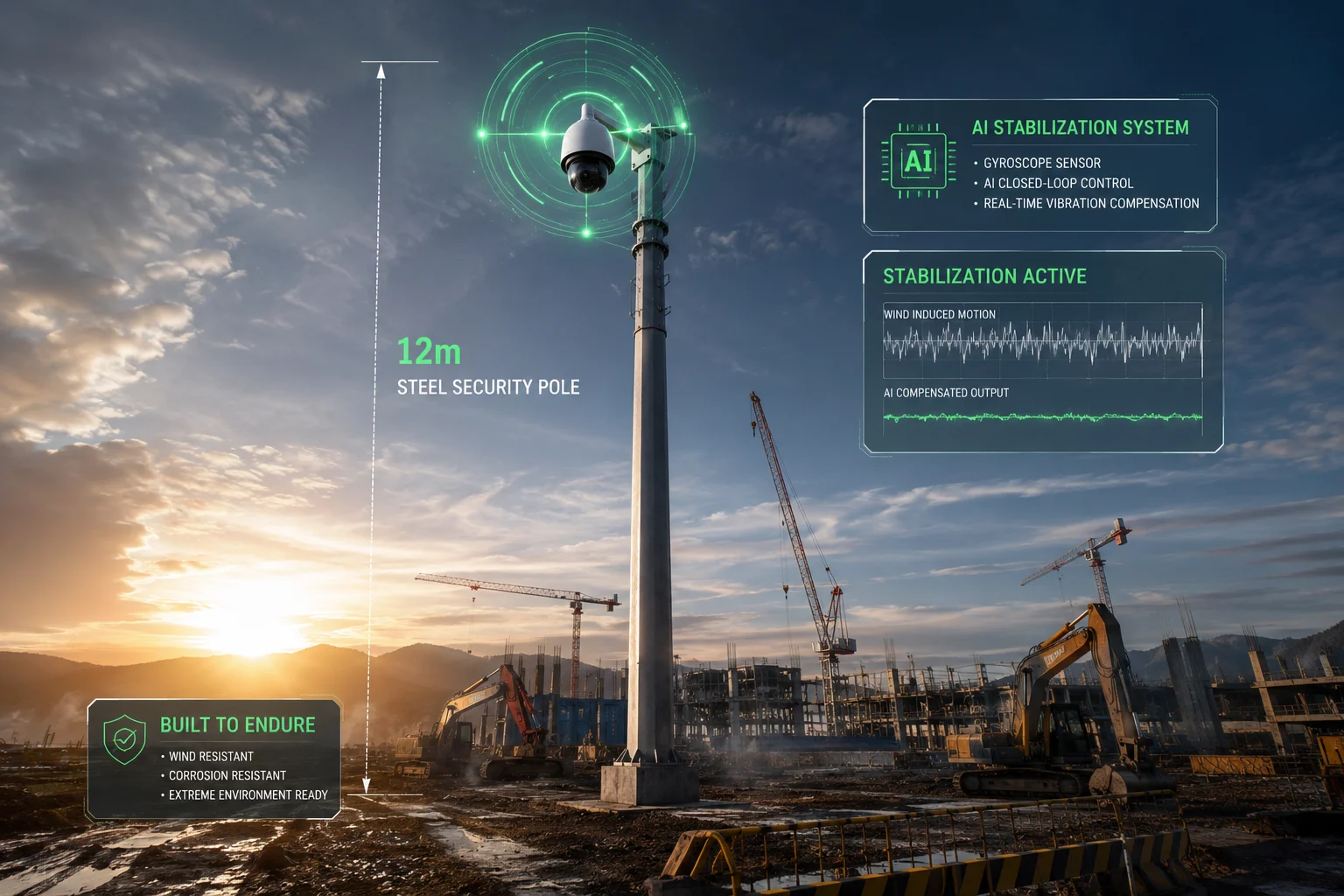
I deployed a 40X laser PTZ on a 12-meter steel pole at a construction site last year. Every time a truck drove past, the pole swayed. On the monitor, the laser spot danced across the target like a flashlight in an earthquake. That’s when I learned why vibration compensation matters.
The system fights vibration blur through three methods: a gyroscope sensor detects pole sway and sends counter-movement commands to the laser motor, the AI closed-loop reads brightness distribution on the target and corrects in real time, and digital image stabilization smooths the final video output.
 vibration blur prevention laser PTZ high zoom tracking
The Vibration Problem at High Zoom
At 1X zoom, a 0.1-degree pole sway is invisible. At 40X zoom, that same 0.1-degree sway moves the image by 4 degrees in the frame. The entire target disappears from view. The laser spot, which is physically mounted on the same swaying pole, moves with the camera body. So the spot stays relatively centered in the image — but both the image and the spot are now pointing at the wrong place.
The real problem is not the laser drifting from the image center. It’s the entire assembly — camera plus laser — oscillating around the target. This creates two visible artifacts:
- Motion blur in the video frames
- Flickering illumination as the laser sweeps on and off the target
Gyroscope-Based Mechanical Stabilization
Higher-end models include a MEMS gyroscope7 inside the PTZ head. This sensor detects angular velocity changes at up to 2000°/s with 0.01° resolution. When it senses vibration:
- It calculates the frequency and amplitude of the oscillation
- It sends counter-movement commands to both the PTZ motors and the laser stepper motor
- These counter-movements are 180° out of phase with the vibration, effectively canceling it
This is the same principle used in optical image stabilization (OIS)8 in smartphone cameras, but scaled up for a 5kg PTZ assembly.
AI Brightness Feedback Loop
This is the most advanced layer. During active tracking, the AI processor continuously analyzes the brightness pattern on the tracked target. Here’s the logic:
- If the upper body of a tracked person is bright and the ground below them is dark, the laser is aimed correctly
- If the upper body goes dark and the ground gets bright, the laser has drifted downward
- The system immediately sends a correction command to tilt the laser up
This feedback runs at 30 frames per second. Each frame gives the AI a new data point. The correction latency is under 33 milliseconds — fast enough to counteract wind-induced sway on most pole installations.
Practical Deployment Advice
| Pole Height | Typical Sway | Compensation Effectiveness | Recommended Action |
|---|---|---|---|
| 4-6 meters | < 0.05° | Full compensation, no visible blur | Standard install |
| 8-12 meters | 0.05-0.2° | Compensated, minor residual at 40X | Add guy wires if possible |
| 15+ meters | 0.2-0.5° | Partial compensation, limit zoom to 20X | Use rigid lattice tower |
For off-grid solar deployments where David’s clients typically work, the pole height is usually 6-8 meters. At this height, the built-in compensation handles normal wind conditions without any additional hardware, and the energy cost is minimal — about 0.3W — which barely impacts the solar power budget9.
The Energy Efficiency Bonus
Here’s something most people miss. When the laser stays perfectly aligned with the target, you don’t need to run it at full power. A well-aimed 500mW laser illuminates a person at 300 meters just as well as a misaligned 2W laser that wastes most of its energy lighting up empty ground.
For a 40Ah battery system running overnight, this efficiency gain translates to 2-3 extra hours of laser runtime. In winter months with short charging days, that difference can mean the system stays operational through the entire night instead of shutting down at 4 AM.
Conclusion
Laser-to-image alignment in high-zoom PTZ cameras relies on three synchronized layers: mechanical motor coupling, periodic self-calibration, and real-time AI correction. Together, they keep the spot locked within 0.1° — even on a swaying pole in the wind.
1. Learn how stepper motors provide precise angular positioning for laser alignment. ↩︎ 2. Understand how field of view changes with zoom and impacts alignment requirements. ↩︎ 3. Learn how temperature changes cause metal parts to expand and affect alignment. ↩︎ 4. See how pre-calculated lookup tables map zoom positions to laser angles. ↩︎ 5. Understand how offset values are stored persistently in non-volatile memory. ↩︎ 6. Learn how predictive feed-forward commands reduce laser lag during fast movements. ↩︎ 7. Explore how MEMS gyroscopes detect vibration and enable counter-movement stabilization. ↩︎ 8. Compare gyroscopic stabilization in PTZ cameras to smartphone OIS technology. ↩︎ 9. Understand how laser alignment efficiency affects energy consumption in off-grid deployments. ↩︎