
I have seen PTZ cameras fail after just months of patrol duty. The motor jams. The image flickers. The client calls, furious. That costly truck roll eats your profit alive.
The infinite 360° pan rotation lifespan is verified through accelerated life testing on slip rings (measured in millions of rotation cycles), continuous whole-unit endurance runs under thermal stress, and real-time monitoring of signal integrity and mechanical precision throughout the entire process.
 PTZ camera infinite 360 pan rotation lifespan testing
Below, I break down exactly how we test each critical component at our Shenzhen factory, what numbers you should demand from any supplier, and how you can run your own shortened verification before committing to a bulk order. Let us walk through the four questions I hear most from integrators like you.
How Many Millions of Rotations Can My Camera Perform Before the Slip Ring Fails?
This is the first question every serious buyer asks me. And it should be. Because the slip ring is the single part that makes “infinite rotation” possible — or kills it.
Industrial-grade slip rings used in our PTZ cameras are rated between 5 million and 10 million rotations. We verify this number on dedicated life-cycle test rigs that spin the slip ring at full rated speed and current while monitoring contact resistance, signal noise, and bit error rate in real time.
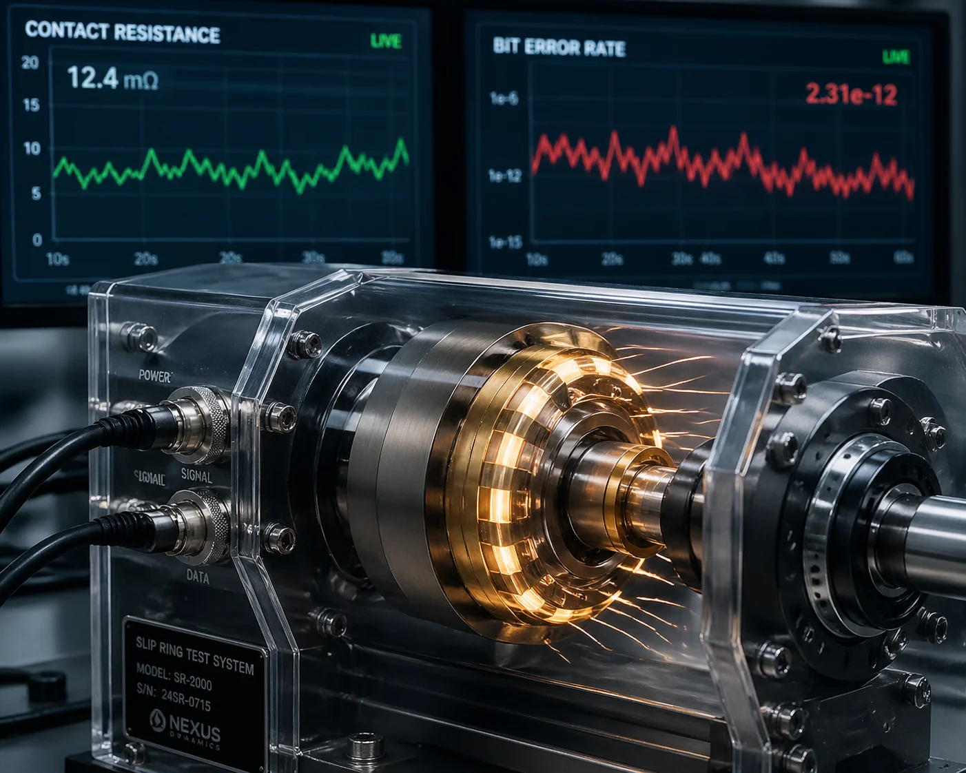 PTZ slip ring life cycle rotation test rig
What Exactly Is a Slip Ring and Why Does It Matter?
A slip ring 1 is a small electromechanical device sitting inside the pan axis of every 360° PTZ camera. It transfers power, video, and data signals from the stationary base to the continuously rotating head. Without it, the internal wiring would twist and snap after a few full turns.
The slip ring has metal brushes (or contacts) that press against rotating rings. Every single rotation causes friction. Over time, that friction wears down the contact surface. Tiny metal particles build up. Those particles cause electrical noise. That noise shows up as video flicker, horizontal lines across your image, or even full camera reboots. i-PRO has documented this exact failure mode in their technical bulletins — dirty or worn slip ring contacts cause full-screen noise and spontaneous restarts during horizontal rotation.
How the Test Rig Works
We do not manufacture slip rings ourselves. We source them from specialized slip ring factories. Those factories run the primary life-cycle validation. Here is what happens on the test bench:
| Test Parameter | What Is Measured | Pass Criteria |
|---|---|---|
| Total rotation count | Cumulative full 360° turns | ≥ 5,000,000 rotations |
| Contact resistance | Ohmic resistance across each channel | Stays within ±10% of initial spec |
| Bit error rate (video) | BER on HD-over-coax or IP signal | < 1 × 10⁻⁹ BER |
| Voltage drop | DC power delivery stability | < 50 mV drop under rated load |
| Noise floor | Electrical noise injected into signal lines | Below -60 dB |
The rig spins the slip ring at its maximum rated RPM under full electrical load — power channels carry rated current, signal channels carry live video data. Sensors log contact resistance every few seconds. If resistance spikes above the threshold, or if the bit error rate climbs, the test stops and that slip ring batch fails.
What This Means for Your Field Deployment
Chinese slip ring suppliers commonly claim lifespans between 20 million and 200 million rotations. Those numbers come from clean-room conditions with no dust, no humidity swings, and no temperature extremes. Real-world life will be shorter. That is why we apply a safety factor. We rate our PTZ cameras at 5 to 10 million rotations — a conservative number that accounts for dust ingress, temperature cycling, and the vibration of outdoor mounting poles.
For a camera doing continuous 360° patrol at 6 RPM, 5 million rotations equals roughly 19 months of non-stop spinning. In practice, most patrol schedules are not 24/7 continuous rotation. A typical preset tour might rotate the camera for 30% of each hour. Under that usage pattern, 5 million rotations translates to approximately 5 years of reliable field service.
When you evaluate a supplier, ask for the slip ring datasheet. Look for the rated rotation count and the test conditions. If they cannot provide it, that is a red flag.
Do You Conduct Continuous Rotation Tests in High-Temperature Chambers for Reliability?
I get this question a lot from integrators deploying in the Middle East, the American Southwest, or any site where summer temperatures push past 50°C. Heat kills lubricant. Heat softens grease. Heat accelerates wear.
Yes. We run continuous 360° rotation endurance tests inside climate chambers set to 60°C for extended periods. This accelerated thermal aging validates that the motor, gearbox lubricant, slip ring, and bearing system all survive the equivalent of 3 to 5 years of harsh outdoor service without mechanical degradation or signal loss.
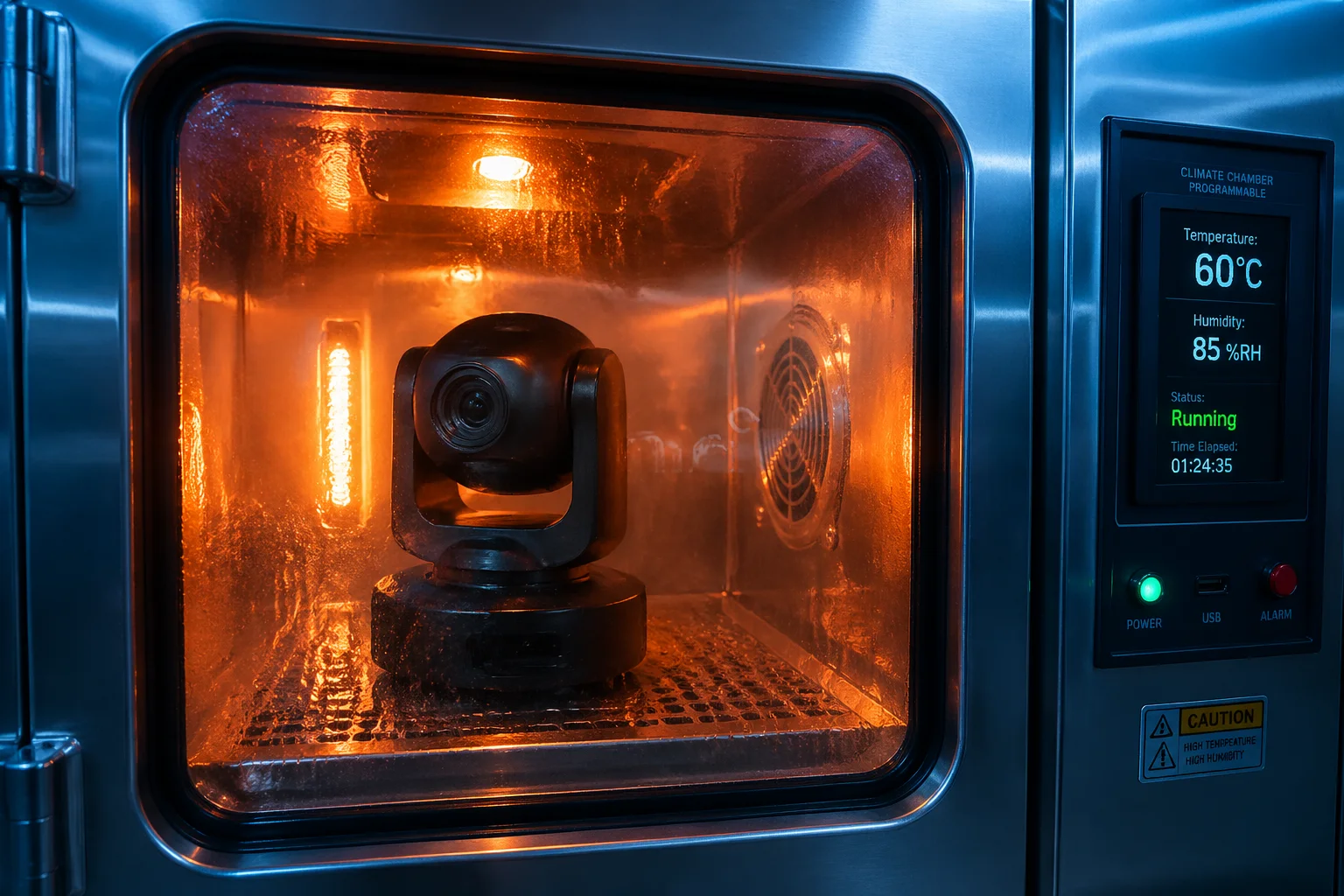 PTZ camera high temperature chamber rotation reliability test
Why Room-Temperature Testing Is Not Enough
A PTZ camera that spins perfectly at 25°C in a lab may fail within months in a desert. The reason is simple: lubricating grease inside the bearing and gear mechanism changes viscosity with temperature. At 60°C, cheap grease thins out, migrates away from the contact surfaces, and leaves metal grinding on metal. At -30°C, the same grease thickens and the motor stalls because it cannot overcome the resistance.
We test at both extremes. But the high-temperature test is the more punishing one for rotation lifespan, because heat accelerates every wear mechanism simultaneously — brush oxidation in the slip ring, grease breakdown in the bearings, and belt relaxation in the drive train.
Our Chamber Test Protocol
Here is the step-by-step process we follow:
- Sample selection. We pull 5 to 10 units from the production line at random. No cherry-picking.
- Chamber setup. The climate chamber is set to 60°C with 85% relative humidity. This simulates a worst-case outdoor enclosure in direct sun.
- Rotation script. Each camera runs a patrol script: continuous 360° pan at maximum speed (600°/s), alternating with preset-to-preset jumps every 30 seconds.
- Duration. The test runs for a minimum of 500 hours. Some batches run 1,000 hours.
- Monitoring. We record video output on a loop and flag any frame with noise, flicker, or dropout. We also log motor current draw — a rising current means increasing mechanical friction.
| Test Condition | Setting | Purpose |
|---|---|---|
| Temperature | 60°C | Simulate peak solar enclosure heat |
| Humidity | 85% RH | Accelerate corrosion on contacts |
| Rotation speed | Max (600°/s) | Maximize mechanical stress per hour |
| Duration | 500–1,000 hours | Equivalent to 3–5 years field use |
| Video monitoring | Continuous recording | Detect signal degradation instantly |
What Failures Look Like in the Chamber
When a unit fails, it usually shows one of three symptoms. First, the motor current spikes and the pan movement becomes jerky — this means the grease has dried out or migrated. Second, the video feed develops horizontal lines or static — this means the slip ring contacts are oxidizing or accumulating debris. Third, the camera reboots mid-rotation — this means the slip ring has a momentary open circuit on the power channel.
Any of these symptoms during the 500-hour window means the design or the component batch does not meet our standard. We trace the root cause, replace the failed component (often the grease type or the slip ring supplier), and re-run the test.
For your projects in hot climates, David, this test is your insurance policy. Ask any supplier: “Show me your high-temperature continuous rotation test report.” If they hesitate, move on.
What Is the MTBF (Mean Time Between Failures) for Your PTZ’s Horizontal Drive System?
MTBF sounds like a simple number. But I have learned that many buyers misunderstand what it actually represents — and some suppliers exploit that confusion.
The MTBF 2 for our PTZ horizontal drive system exceeds 30,000 hours under standard patrol conditions. We derive this figure from accelerated life testing data combined with field return rate analysis, focusing specifically on the stepper motor, synchronous belt, and slip ring as the three primary failure points.
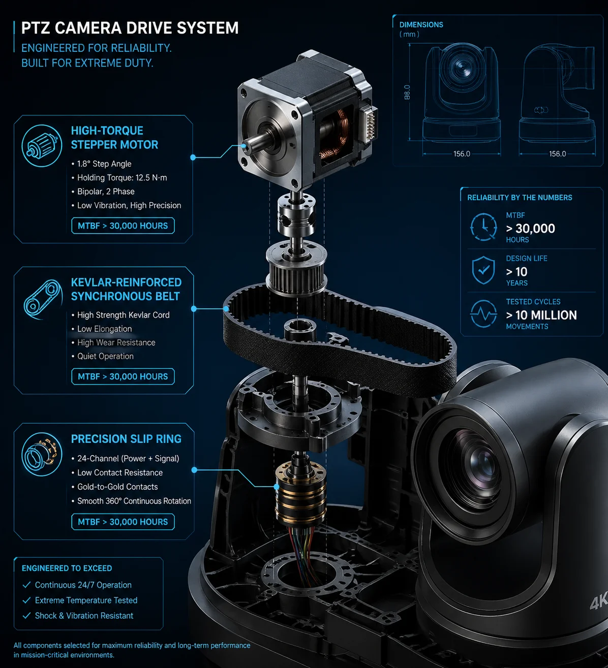 PTZ horizontal drive system MTBF reliability analysis
How We Calculate MTBF
MTBF is not a guarantee that your camera will last 30,000 hours. It is a statistical average. If you deploy 100 cameras, MTBF tells you the average time before one of them experiences a horizontal drive failure. Here is how we build that number:
Accelerated Life Test Data
We take the results from our chamber tests and continuous rotation tests. We record how many hours each sample ran before showing any sign of degradation. We then apply an acceleration factor (based on the Arrhenius model for thermal aging) to convert the 60°C test hours into equivalent 25°C field hours.
Field Return Rate Analysis
We track every warranty claim from our global customer base. We categorize each claim by failure mode: power board, lens, IR LEDs, pan motor, tilt motor, slip ring, and so on. The horizontal drive failures get their own MTBF calculation based on actual return volumes divided by total deployed unit-hours.
The Three Components That Define Horizontal Drive MTBF
| Component | Typical Failure Mode | Our Design Countermeasure |
|---|---|---|
| Stepper motor | Bearing wear → increased friction → stall | Sealed bearings with high-temp grease, rated 20,000+ hours |
| Kevlar-reinforced belt | Stretching → preset position drift | Pre-tensioned at factory, verified after 100,000 cycles |
| Slip ring | Contact wear → signal noise → reboot | Gold-on-gold contacts, rated 5M+ rotations |
Preset Accuracy as a Wear Indicator
One of the most practical ways to detect early drive system wear is to check preset accuracy. After our 100,000-cycle fatigue test (where the camera jumps between two presets 180° apart at full speed), we measure whether the camera returns to the exact same pixel position.
Our pass/fail threshold is ±0.1°. If the camera drifts beyond that, it means either the belt has stretched or the motor encoder has accumulated error. Both are early signs that the mechanical system is approaching end of life.
This is a test you can replicate yourself, David. Set two presets. Run an automated tour for a week. Then check if the camera still lands on the exact same spot. If it drifts, you have a problem — and you found it before your client did.
Why MTBF Alone Is Not Enough
MTBF is an average. It does not tell you about infant mortality (early failures from manufacturing defects) or wear-out failures (end-of-life degradation). That is why we combine MTBF with our burn-in aging process. Every camera runs for 48 hours on the aging rack before shipment. This catches the infant mortality failures before they reach your warehouse.
Will the Video Signal Degrade or Flicker After a Year of Constant 360° Patrolling?
This is the question that keeps integrators up at night. Because a camera that still rotates but delivers garbage video is worse than a camera that stops completely. At least a dead camera triggers an alarm. A degraded image just silently ruins your evidence.
Video signal can degrade after prolonged 360° patrolling if the slip ring contacts wear down or accumulate conductive debris. We prevent this through gold-plated slip ring contacts, software-based auto-calibration routines that clean the contact surface every 24 hours, and S-curve soft-start algorithms that reduce mechanical shock by approximately 30%.
 PTZ video signal quality after long term 360 patrol testing
The Root Cause of Video Degradation During Rotation
When you see horizontal lines, static, or brief blackouts only during pan movement, the cause is almost always the slip ring. Here is the chain of events:
The metal brush rubs against the rotating ring. Microscopic particles of metal flake off. These particles accumulate in the contact gap. They create intermittent short circuits between adjacent signal channels. The result: noise injected directly into your video signal path.
i-PRO’s engineering team has published detailed documentation on this exact phenomenon. They recommend a “Position Refresh” function — the camera periodically rotates to a specific angle that wipes the slip ring contacts clean. We implement a similar approach.
Our Three-Layer Protection Strategy
Layer 1: Hardware — Gold-on-Gold Contacts
We specify slip rings with gold-plated brushes and gold-plated rings. Gold does not oxidize. It produces far less conductive debris than silver or copper alloys. The trade-off is cost — gold contacts add roughly $2–3 to the BOM. But for a camera that sells at industrial pricing, that is a trivial investment against a warranty claim.
Layer 2: Software — Auto-Calibration and Position Refresh
Every 24 hours, our firmware triggers an automatic self-check routine. The camera rotates to its home position, verifies the encoder zero-point, and performs a slow full rotation. This slow rotation serves two purposes: it redistributes lubricant across the bearing surfaces, and it allows the slip ring brushes to sweep debris off the contact rings.
This auto-calibration also corrects for cumulative positional drift. After thousands of high-speed rotations, tiny encoder errors can stack up. The daily reset eliminates that accumulated error and keeps preset accuracy within ±0.1°.
Layer 3: Software — S-Curve Acceleration Control
Every time the camera starts or stops a pan movement, the motor experiences a mechanical shock. Sudden starts and stops are the number one cause of gear tooth wear and belt fatigue. Our firmware uses S-curve acceleration profiles instead of linear ramp-ups. The motor accelerates gradually, reaches cruise speed, then decelerates gradually.
This is not just theory. In our internal testing, S-curve control extended the mechanical lifespan of the drive system by approximately 30% compared to linear acceleration. The camera feels smoother, sounds quieter, and lasts longer.
What You Should Test Before Committing to a Large Order
Here is my practical advice for any integrator evaluating PTZ samples:
- Set the camera to continuous 360° patrol at medium speed.
- Record the video output to an NVR.
- Let it run for 2 weeks straight.
- Review the recorded footage. Scrub through it at 16x speed. Look for any frame with horizontal lines, static bursts, color shifts, or brief blackouts.
- After the 2-week run, check preset accuracy. Does the camera still return to the exact same position?
If the camera passes this test cleanly, you can have reasonable confidence in its long-term rotation reliability. If it shows any artifacts within 2 weeks, do not buy it — because those problems will only get worse with time.
This is exactly the kind of shortened life test that separates serious suppliers from catalog resellers. We welcome it. In fact, we encourage every new client to run this test on our samples before placing a production order.
Conclusion
The 360° infinite pan lifespan comes down to slip ring rotation count, drive system fatigue resistance, and software-based wear protection — all verified through accelerated life testing, not guesswork.
1. Slip ring mechanical and electrical operation for PTZ cameras. ↩︎ 2. MTBF statistical calculation from accelerated life test data. ↩︎ 3. Contact resistance monitoring for slip ring wear detection. ↩︎ 4. Gold-on-gold contact benefits for low signal noise. ↩︎ 5. Arrhenius acceleration factor for thermal aging tests. ↩︎ 6. S-curve motor acceleration for reduced mechanical shock. ↩︎ 7. i-PRO slip ring maintenance and position refresh function. ↩︎ 8. Burn-in testing for infant mortality failure detection. ↩︎ 9. Preset accuracy degradation as belt wear indicator. ↩︎ 10. Kevlar belt pre-tensioning for zero stretch over time. ↩︎