
I’ve seen lightning kill a $2,000 camera through a single Ethernet cable. In off-grid solar deployments, the RJ45 port is your weakest link against static discharge.
Independent ESD protection for the RJ45 interface uses a three-layer defense architecture: a shielded metal connector grounded to the chassis, a low-capacitance TVS diode array that clamps voltage spikes in nanoseconds, and an isolation transformer rated for 1500V–2000V between the cable and the internal SoC.
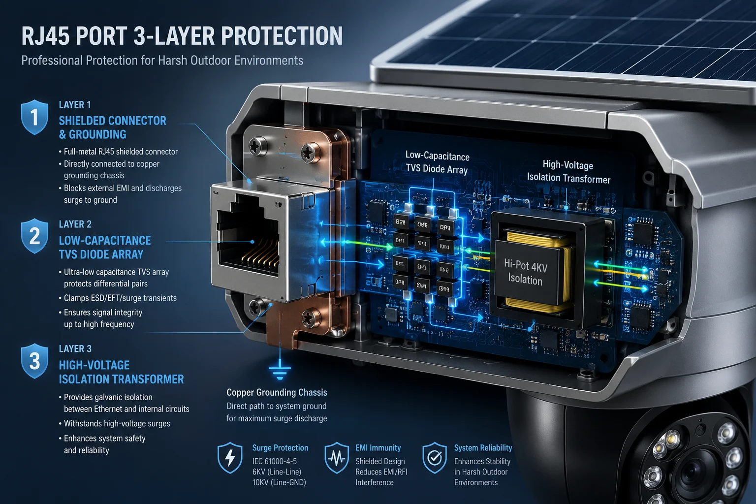 RJ45 ESD protection for solar PTZ camera
Below, I break down each layer of this protection system. I’ll explain what each component does, why it matters for your field deployments, and what you should verify before you sign off on any hardware order.
Table of Contents
Does the Camera Use Dedicated TVS Diode Arrays to Block 15KV Air-Discharge Static?
I’ve tested boards where a single missing TVS chip turned a minor static event into a dead SoC. The TVS array is the fastest-reacting guard in the entire protection chain.
Yes. We place dedicated low-capacitance TVS diode arrays2 on all four data pairs (pins 1, 2, 3, 6) between the RJ45 connector and the Ethernet transformer. These arrays respond in nanoseconds and clamp voltages to safe levels before any energy reaches the processor.
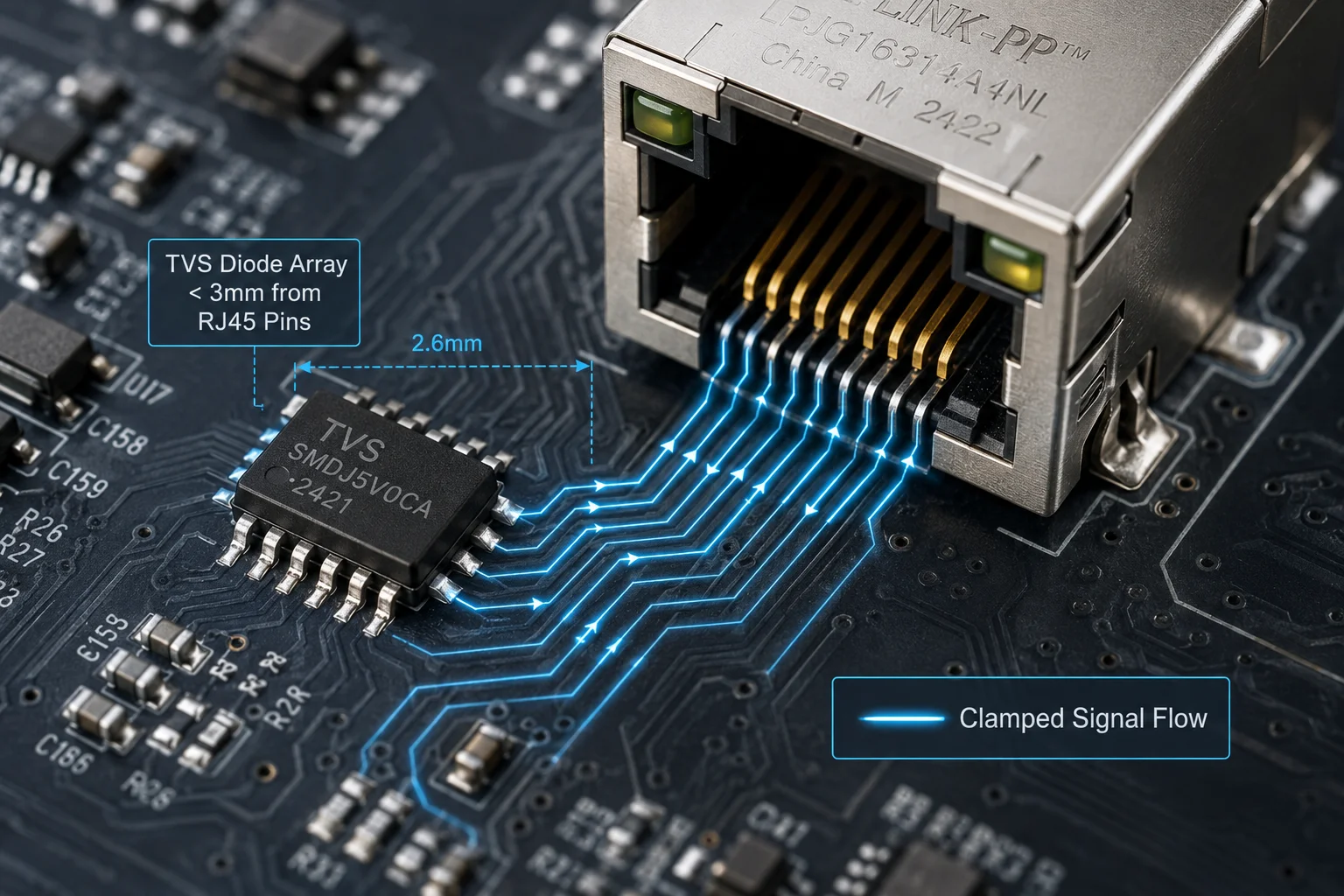 TVS diode array on RJ45 data lines
What a TVS Diode Array Actually Does
A TVS (Transient Voltage Suppressor) diode array sits in parallel with the signal lines. Under normal conditions, it acts like it’s not there. Its impedance is extremely high, so data flows past it without any interference.
But the moment voltage on the line exceeds a set threshold — say 5V or 12V depending on the design — the TVS switches from high-impedance to low-impedance in less than one nanosecond. It creates a short path to ground. The excess energy dumps into the ground plane instead of traveling deeper into the circuit board.
Why Low Capacitance Matters
Here’s a detail many buyers overlook. A TVS diode adds parasitic capacitance13 to the signal line. If that capacitance is too high, it distorts the Ethernet signal. For 100Mbps Fast Ethernet7, you need TVS capacitance below 5pF. For Gigabit Ethernet8, you want it below 1pF.
We use arrays rated at less than 0.5pF per line. This means the TVS does not degrade signal integrity, even at Gigabit speeds. Your data packets arrive clean.
Clamping Voltage vs. Breakdown Voltage
These are two different specs, and confusing them is a common mistake.
| Parameter | Definition | Typical Value |
|---|---|---|
| Breakdown Voltage | The voltage where the TVS starts to conduct | 6V–12V |
| Clamping Voltage | The max voltage the TVS allows during a surge | 15V–25V |
| Response Time | Time from surge arrival to full conduction | < 1 ns |
| Capacitance | Parasitic load added to the signal line | < 1 pF |
The clamping voltage11 is what actually protects your SoC. If your processor’s I/O pins are rated for 3.3V with a 5V absolute maximum, the TVS must clamp well below the damage threshold. Our design clamps at under 15V on the data lines, which the isolation transformer further attenuates before it reaches the PHY chip.
Placement on the PCB
Physical placement matters. The TVS array must sit as close to the RJ45 connector as possible. If there’s a long PCB trace between the connector and the TVS, that trace itself becomes an antenna. It picks up induced voltage before the TVS can react. In our board layout, the TVS pads are within 3mm of the connector pins.
How Do You Prevent ESD from the Technician’s Hands from Damaging the Internal SoC?
I’ve watched a technician plug in a cable on a dry winter day and fry a board with nothing more than finger static. Human-body ESD is a real and common threat during installation.
We prevent human-body ESD damage through the combination of the shielded RJ45 metal shell (grounded to chassis), the internal isolation transformer providing 2000V galvanic separation, and the TVS arrays that catch any residual spike before it reaches the SoC’s Ethernet PHY pins.
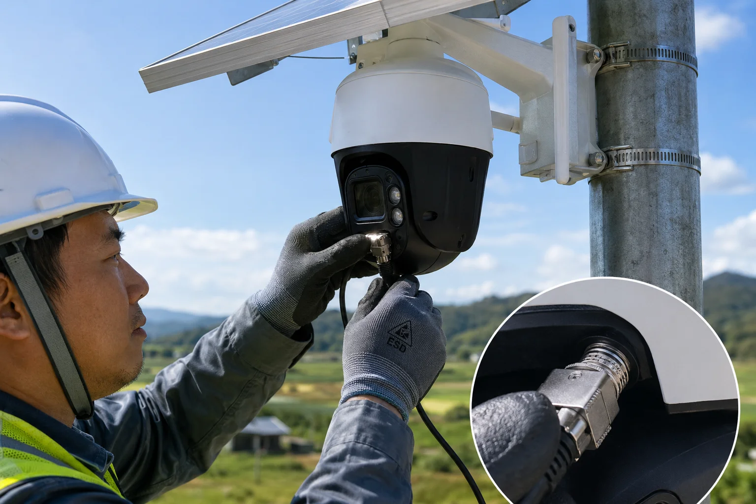 Technician installing RJ45 cable on solar camera
The Human-Body Model (HBM)
The industry standard for simulating a technician’s touch is the Human-Body Model3. It assumes a 100pF capacitor charged to a given voltage, discharged through a 1500-ohm resistor. A person walking across carpet in dry conditions can build up 15,000 volts or more. When they touch a metal connector, that charge dumps in microseconds.
How the Three Layers Work Together Against Hand ESD
The first thing the static charge hits is the metal shell of the RJ45 connector. If the shell is properly grounded to the camera’s chassis (and the chassis is grounded to the mounting pole), most of the charge drains away immediately. It never enters the signal pins.
Any charge that does enter through the signal pins hits the TVS array next. The TVS clamps the voltage and routes the energy to the PCB ground plane.
Finally, the Ethernet transformer provides galvanic isolation6. Even if some transient energy passes the TVS, the transformer’s primary and secondary windings are physically separated. There is no direct copper path from the cable side to the SoC side. The transformer can withstand 1500V to 2000V of potential difference between its two sides.
Why Grounding Is the Critical First Step
David, here’s what I need you to understand for your Texas deployments. If your mounting pole has no earth ground10 connection, the metal shell of the RJ45 has nowhere to send the static charge. The TVS array becomes the first and only line of defense. It will still protect the SoC, but it absorbs more energy per event. Over hundreds of events across years of service, this shortens the TVS lifespan.
A proper earth ground — a copper rod driven at least 8 feet into soil, connected to the pole with a bonding wire — gives static a direct path to earth. The electronics never see it.
Installation Best Practices
| Risk Factor | Without Ground | With Proper Ground |
|---|---|---|
| ESD energy reaching TVS | 100% of discharge | < 5% of discharge |
| TVS lifespan | Reduced over time | Full rated lifespan |
| SoC damage risk | Low (TVS protects) | Near zero |
| Compliance with IEC 61000-4-2 | Marginal | Full compliance |
Always connect the camera chassis to the pole’s grounding system before you plug in any cables. This one step eliminates most ESD risk from human contact.
Is the RJ45 Port Shielded and Grounded to the Camera’s Metal Chassis?
I’ve opened cameras from budget suppliers and found the RJ45 shell floating — connected to nothing. That metal shell is useless if it doesn’t have a ground path.
Yes. Our RJ45 connector uses a full metal shield that is soldered directly to the PCB ground plane and bonded to the camera’s die-cast aluminum chassis through dedicated grounding tabs. This creates a continuous conductive path from the cable shield to earth ground.
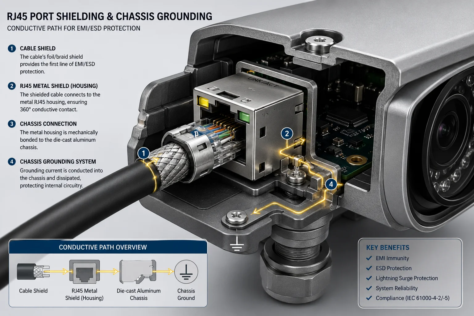 Shielded RJ45 connector grounded to camera chassis
Shielded vs. Unshielded Connectors
An unshielded RJ45 (used in most indoor consumer devices) has a plastic housing. It offers zero protection against external electromagnetic interference or static discharge. A shielded RJ459 has a stamped metal shell that wraps around the plastic insert. This shell serves two purposes: it blocks EMI from entering or leaving the cable, and it provides a drain path for static charges.
But the shield only works if it connects to something. In our design, the metal tabs on the RJ45 shell solder to large ground pads on the PCB. These pads connect through multiple vias to the internal ground plane. The ground plane then connects to the chassis through a dedicated bonding point — usually a screw terminal or spring contact where the PCB meets the metal housing.
The Cable Side of the Equation
The camera’s shielded connector is only half the solution. The Ethernet cable must also be shielded (FTP or SFTP type). The cable’s foil or braid shield must make contact with the RJ45 plug’s metal shell. When you crimp a shielded plug, the cable shield folds back over the plug body and touches the metal housing.
This creates a continuous shield from one end of the cable to the other. Any electromagnetic interference or induced voltage on the cable’s exterior drains through the shield to ground at both ends.
What Happens Without Proper Grounding
If the RJ45 shell is not grounded, static charge accumulates on the metal surface. Eventually, it arcs to the nearest conductor — which might be a signal pin. This is worse than having no shield at all, because the shield acts as a charge collector with no drain path.
I’ve seen this exact failure mode in competitor products. The RJ45 shell was connected to the PCB, but the PCB ground was floating relative to the chassis. During a thunderstorm, induced charge built up on the cable shield, accumulated on the connector shell, and eventually arced across to the data pins. The TVS caught most of it, but repeated events degraded the protection over one rainy season.
Our Grounding Architecture
Our cameras use a die-cast aluminum body. The PCB mounts directly to this body with metal standoffs. The standoffs provide both mechanical support and electrical bonding. The RJ45 ground connects through the PCB ground plane14, through the standoffs, into the aluminum chassis. From there, the chassis connects to the mounting bracket, which connects to the pole, which connects to the earth ground rod.
Every link in this chain matters. One missing connection breaks the entire path.
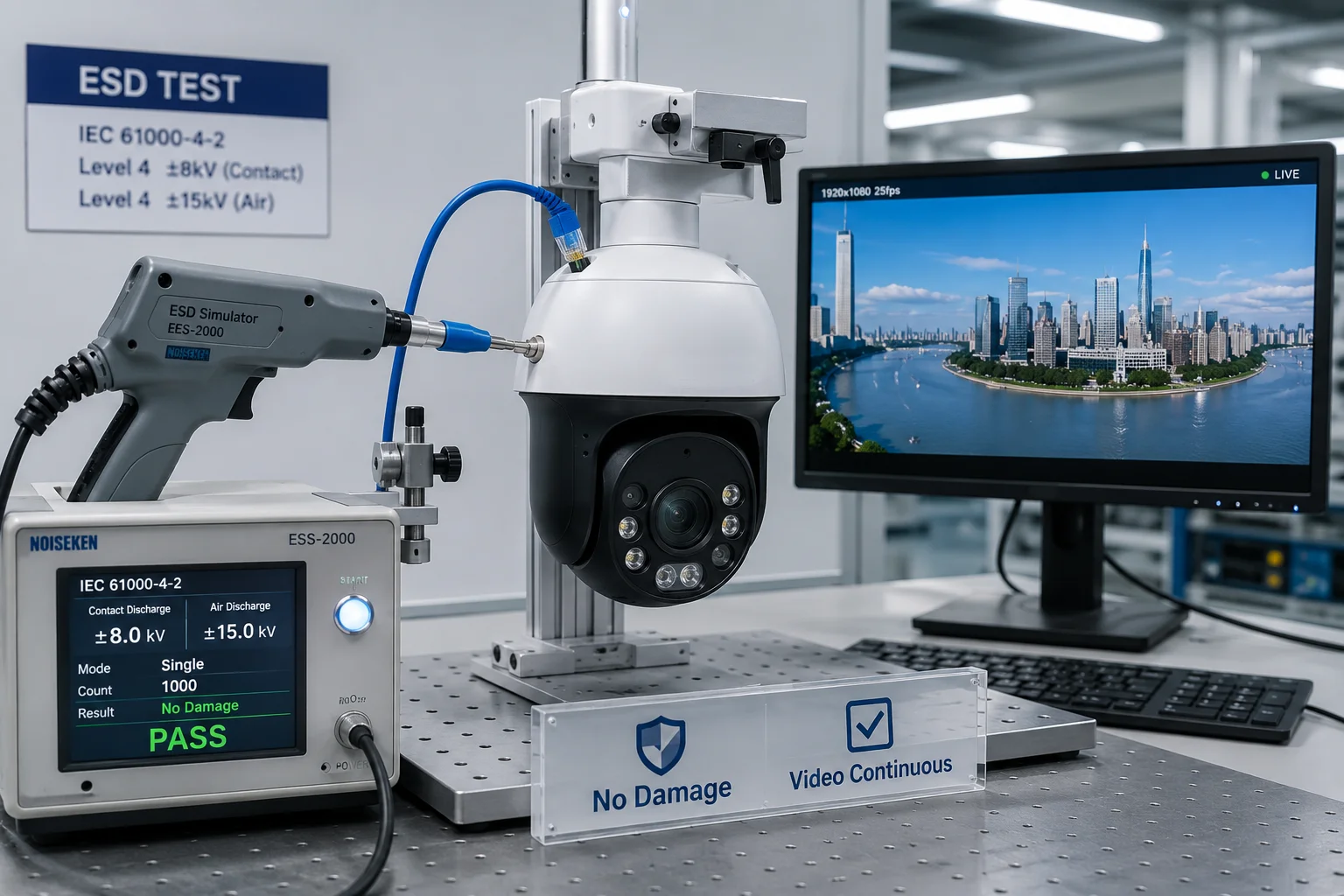
Can I See the ESD Test Report for the Internal Ethernet PHY and Data Transformers?
I’ve had buyers ask for test reports after a failure. The right time to ask is before you place the order — not after a storm takes out a batch of cameras.
Yes. We provide full IEC 61000-4-2 ESD test reports showing ±6KV contact discharge and ±8KV air discharge compliance on the RJ45 interface. These reports cover the complete signal path including the PHY chip, transformer, and TVS protection circuit tested as an integrated system.
 ESD test report for Ethernet PHY and transformer
What the Test Report Covers
Our ESD testing follows IEC 61000-4-21, the international standard for electrostatic discharge immunity. The test applies controlled ESD pulses directly to the RJ45 port while the camera is powered on and streaming video. The camera must continue operating without interruption, data loss, or permanent damage.
The test levels we certify to:
| Test Type | Voltage Level | Standard | Result Criteria |
|---|---|---|---|
| Contact Discharge | ±6 KV | IEC 61000-4-2 Level 3 | No interruption |
| Air Discharge | ±8 KV | IEC 61000-4-2 Level 3 | No interruption |
| Surge (line-to-line) | ±2 KV | IEC 61000-4-5 | No damage |
| Surge (line-to-ground) | ±4 KV | IEC 61000-4-5 | No damage |
“No interruption” means the video stream continues without a single dropped frame. “No damage” means the device passes full functional testing after the surge event.
The Difference Between Component-Level and System-Level Testing
Some suppliers show you a TVS datasheet rated for 15KV and call it a day. That’s component-level data. It tells you the TVS chip itself can survive 15KV. It does not tell you the complete circuit — connector, traces, TVS, transformer, PHY — survives as a system.
Our test reports are system-level. We test the finished camera, fully assembled, with firmware running. The ESD gun touches the actual RJ45 port on the actual product. This catches problems that component datasheets cannot reveal: poor PCB layout, inadequate ground connections, or transformer saturation under combined stress.
What to Ask Your Supplier
David, when you request ESD test reports, ask these specific questions:
- Was the test performed on the finished product or just on individual components?
- Was the device powered on and streaming during the test?
- What was the pass/fail criteria — survival only, or continuous operation?
- Were both contact and air discharge tested?
- Was surge testing (IEC 61000-4-5) also performed on the Ethernet port?
If a supplier cannot answer these questions clearly, their “ESD protection” claim is marketing, not engineering.
PoE Considerations for Your Network
One more point for your field deployments. If you use PoE (Power over Ethernet)5 injectors to power local switches or access points in your solar monitoring setup, the power-carrying pairs (4/5 and 7/8) also need surge protection. A lightning-induced surge on the power pairs can bypass all the data-line protection and enter the camera through the PoE circuit.
Make sure your PoE injector has its own surge protection rated to at least IEC 61000-4-54 Level 2. Otherwise, the power pairs become an unprotected highway for surge energy to reach your camera’s internal power regulator.
Conclusion
Independent ESD protection for the RJ45 port requires three layers working together: shielded grounding, TVS clamping, and transformer isolation. Verify system-level test reports and ensure proper earth grounding at every installation site.
1. The international standard for electrostatic discharge immunity testing. ↩︎ 2. A transient voltage suppressor array that clamps voltage spikes in nanoseconds. ↩︎ 3. A standard model for simulating electrostatic discharge from a human touch. ↩︎ 4. The international standard for surge immunity testing. ↩︎ 5. Technology that transmits electrical power along with data on Ethernet cables. ↩︎ 6. Electrical separation between circuits that prevents DC current flow while allowing signal or power transfer. ↩︎ 7. Ethernet standard supporting 100 Mbps data transfer rate. ↩︎ 8. Ethernet standard supporting 1 Gbps data transfer rate. ↩︎ 9. A connector with a metal shell that blocks EMI and provides a discharge path for static. ↩︎ 10. A direct physical connection to the earth used to dissipate static charges safely. ↩︎ 11. The maximum voltage a TVS diode allows to pass during a surge event. ↩︎ 12. The voltage at which a TVS diode begins to conduct current. ↩︎ 13. Unwanted capacitance introduced by a component that can degrade high-speed signal quality. ↩︎ 14. A large area of copper on a PCB that serves as a common return path and noise shield. ↩︎