
I have lost count of how many times a client called me about a dead camera at a remote site — with no one nearby to press a reset button.
A well-designed 4G solar PTZ system uses a low-power MCU as a “sentry” that keeps watching battery voltage and PIR signals while the main processor sleeps. When power drains too low, the system hibernates automatically. When solar charging restores the battery to a safe level, the system cold-boots itself, reconnects to 4G, and resumes recording — all without any human touch.
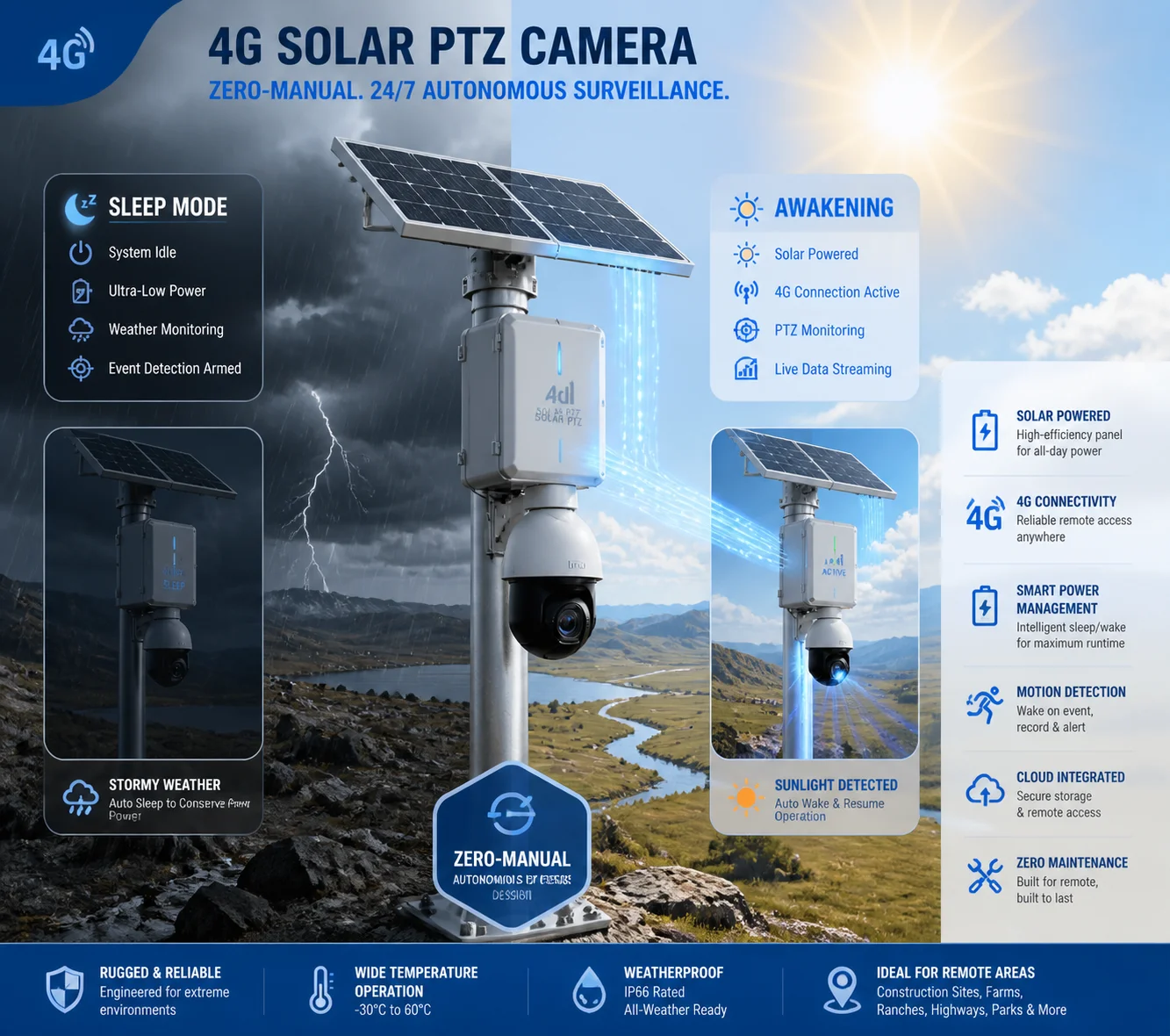 solar 4g ptz camera auto sleep and self restart system
Below, I will walk you through the exact battery thresholds, the solar recovery logic, the 4G reconnection process, and the file system protection that makes all of this work. If you deploy cameras in places where a truck roll costs more than the camera itself, this is the article you need to read.
Table of Contents
At What Battery Percentage Will the Camera Enter an Emergency Hibernation Mode?
I have seen too many cheap cameras drain their batteries to zero and then refuse to wake up — ever. That single failure can kill a whole project’s reputation.
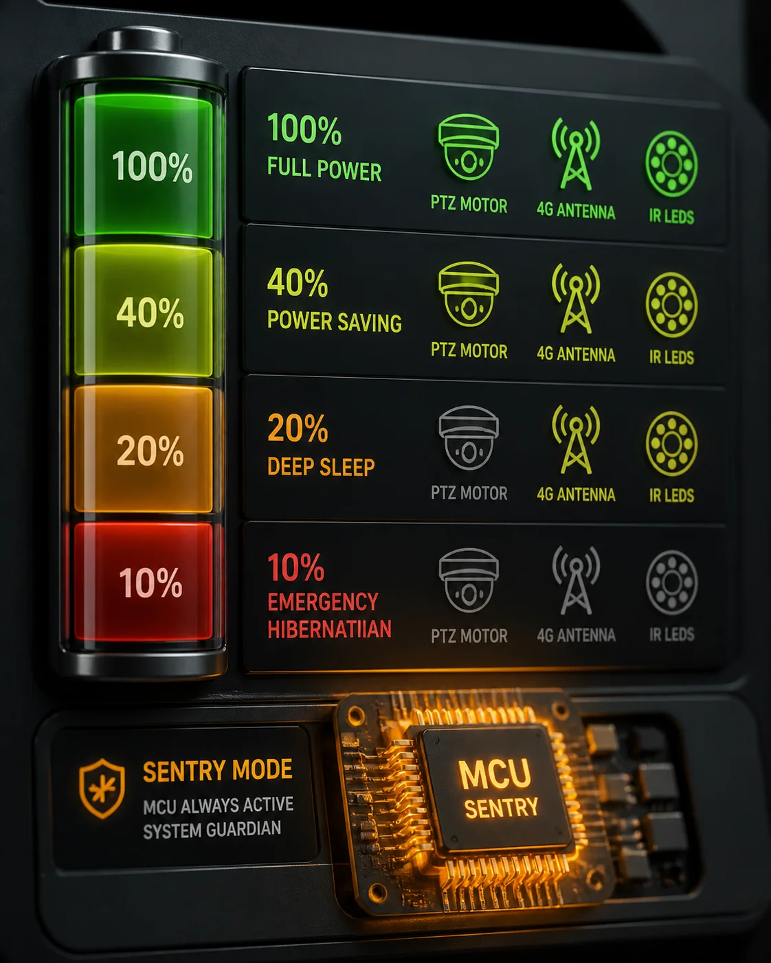
Most quality 4G solar PTZ cameras start reducing functions at around 30% battery and enter full emergency hibernation at roughly 10–15%. At that point, the system cuts power to the SoC, 4G module, IR LEDs, and PTZ motor. Only a tiny MCU stays alive, sipping about 0.01–0.1W, waiting for the battery to recharge.
 solar camera low battery hibernation threshold
How the Threshold Ladder Works
The system does not just have one “off” switch. It uses a stepped approach. Think of it like a building shutting down floor by floor during a blackout. The elevator stops first. Then the lights dim. Then only the emergency exit signs stay on.
Here is what a typical threshold ladder looks like in practice:
| Battery Level | System Behavior | Active Modules |
|---|---|---|
| Above 40% | Full operation — continuous recording, PTZ patrol, 4G live stream | SoC, 4G, PTZ motor, IR/white LEDs, PIR |
| 20–40% | Smart power-saving mode — no continuous recording, PIR-triggered recording only | SoC (reduced clock), 4G (heartbeat only), PIR |
| 10–20% | Deep sleep — no PIR wake-up allowed, only APP remote wake-up or scheduled check-in | MCU, 4G (periodic heartbeat) |
| Below 10% | Emergency hibernation — full shutdown to protect battery from over-discharge | MCU only (monitoring voltage) |
Why Over-Discharge Protection Matters
Lithium batteries have a hard rule: if you drain them below a certain voltage (typically around 10.8V for a 12V pack), the cells get damaged permanently. Their capacity shrinks. Their internal resistance goes up. After a few deep discharges, a 30Ah battery might behave like a 20Ah battery.
So the BMS (Battery Management System) inside the solar controller acts as a gatekeeper. When voltage hits that critical floor, it physically disconnects the load. This is called Low Voltage Disconnect (LVD) for lithium batteries 1. It is a hardware-level cutoff, not a software suggestion. Even if the firmware crashes, the BMS still protects the battery.
What Happens Inside the Camera During Hibernation
When the camera enters emergency hibernation, the power management unit (PMU) on the main board executes a shutdown sequence:
- The PTZ motor is locked and de-energized.
- The image sensor and video encoder are powered off.
- The 4G module sends a final “going offline” message to the cloud platform, then shuts down.
- The IR or white-light LEDs are cut.
- The main SoC saves its last state to flash memory, then powers down.
- Only the low-power MCU remains active. It draws about 50–100 milliwatts. Its only job is to watch the battery voltage pin and wait for recovery.
This sequence matters. If you just yank the power without saving state, you risk corrupting the file system. I will cover that in detail in the last section.
For a deeper understanding of battery protection thresholds, review this guide to battery management system design 2.
Will the System Automatically Resume Recording Once the Solar Panel Recharges?
I have had clients ask me: “Han, do I need to send someone out to turn the camera back on after a cloudy week?” The answer should always be no.
Yes. Once the solar panel recharges the battery above a safe recovery threshold — typically around 12.6V or about 40% capacity — the system automatically powers on, boots its firmware, reconnects to the 4G network, and resumes its last working mode, including PTZ preset position and recording schedule. No button press is needed.
 solar panel recharge camera auto restart recovery
The “Dead-Start” Logic Explained
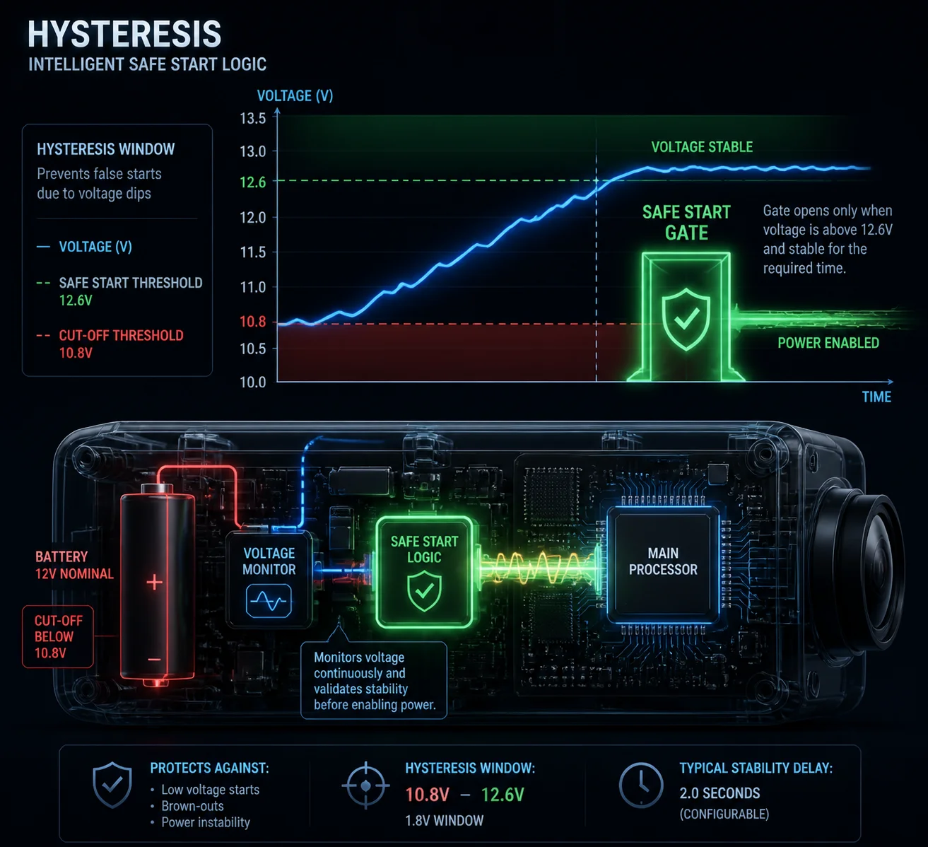
Here is the key design principle: the recovery voltage is set higher than the shutdown voltage. This gap is called hysteresis. It exists for a very important reason.
Imagine the sun comes out weakly at 7 AM. The battery voltage slowly climbs from 10.8V to 11.2V. If the camera turned on at 11.0V, it would immediately start drawing power. That draw would pull the voltage back below 10.8V. The BMS would cut power again. The camera would shut down. Then the voltage would creep back up. The camera would try again. And fail again.
This is called oscillation — a “death loop.” It wastes energy, stresses the battery, and writes garbage data to the SD card. It can kill an SD card in weeks.
How Hysteresis Prevents the Death Loop
| Parameter | Typical Value | Purpose |
|---|---|---|
| LVD (Low Voltage Disconnect) | 10.8V | Protect battery from over-discharge |
| Recovery Voltage (Auto Power-On) | 12.6V | Ensure enough energy to sustain full boot |
| Hysteresis Gap | ~1.8V | Prevent oscillation / death loop |
| Minimum Hold Time | 5–10 minutes | Confirm voltage is stable, not a brief spike |
The system does not just check if the voltage crosses 12.6V once. It waits. It confirms the voltage stays above that level for several minutes. Only then does the MCU release the main power rail and let the SoC boot.
What Happens During the Boot Sequence
Once the MCU decides it is safe to start, the following happens automatically:
- PMU enables main power rail. The DC-DC converters spin up and supply stable voltage to the SoC, memory, and peripherals.
- SoC boots from flash. The RTOS or Linux kernel loads. The firmware reads its last saved configuration from non-volatile memory.
- 4G module initializes. It powers on, searches for a cell tower, registers on the network, and establishes a data connection (APN dial-up).
- Cloud platform reconnection. The camera sends a “hello” packet to the cloud server. The server updates the device status to “online.”
- PTZ returns to preset. If a startup preset was configured, the PTZ motor moves to that position.
- Recording resumes. Based on the saved schedule — continuous, event-triggered, or time-lapse — the camera starts writing video to the SD card or streaming to the cloud.
This entire sequence takes about 30–90 seconds depending on the hardware. The user sees the camera come back online in their app without doing anything. That is what “zero-manual” means in practice.
For more on solar charge controller hysteresis, see this technical explanation of MPPT charge controller logic 3.
Do I Need to Manually Reset the 4G Connection After a Complete Power Drain?
This is one of the most common questions I get from system integrators. They worry that a full power drain will corrupt the 4G module’s settings or SIM registration.
No. You do not need to manually reset the 4G connection. The 4G module is designed to re-initialize itself on every power-up. It re-reads the SIM card, re-registers with the carrier, and re-establishes the APN data session automatically. If the connection fails, the firmware has a built-in retry and self-healing routine.
 4g module auto reconnect after power drain
How 4G Self-Healing Works Step by Step
The 4G module inside a solar PTZ camera is not like a home router that sometimes needs a manual reboot. It is built for unattended operation. Here is the typical self-healing logic:
Step 1: Power-on initialization. When the module gets power, it runs its internal bootloader, loads its firmware, and reads the SIM card’s ICCID and IMSI. This is automatic. No human input is needed.
Step 2: Network search and registration. The module scans available frequencies, finds the strongest cell tower, and registers on the carrier’s network. If the first attempt fails (maybe the tower is busy), it retries with an exponential backoff — first after 5 seconds, then 10, then 30, and so on.
Step 3: APN dial-up. Once registered, the module establishes a data session using the pre-configured APN settings stored in the camera’s firmware. These settings survive power loss because they are saved in non-volatile flash memory.
Step 4: Cloud connection. The camera connects to the cloud platform (like Hik-Connect, TUTK, or a custom MQTT broker). It authenticates with its device ID and token.
What If the Connection Still Fails?
The firmware has multiple fallback layers:
- RF restart: If the module has signal bars but cannot establish a data session, it performs an internal RF reset — essentially turning the radio off and on without rebooting the whole camera.
- Full module restart: If the RF reset does not work after 3 attempts, the firmware power-cycles the entire 4G module via a GPIO pin.
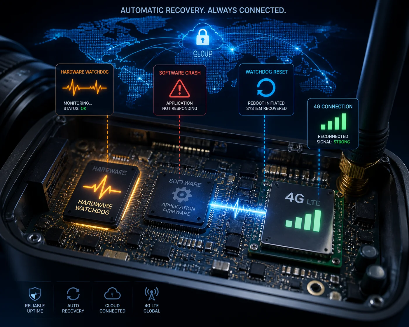
- Full system reboot: If the module still cannot connect after 30 minutes, the hardware watchdog triggers a full system reboot. This is the last resort, and it works because the watchdog is a hardware timer — it does not depend on the software being functional.
The Hardware Watchdog: Your Silent Safety Net
The hardware watchdog deserves special attention. It is a simple but powerful concept:
- The main firmware sends a “heartbeat” signal to a hardware timer chip every few seconds. This is called “feeding the dog.”
- If the firmware crashes, freezes, or gets stuck in an infinite loop, it stops feeding the dog.
- After a preset timeout (typically 120–180 seconds), the watchdog chip pulls the reset pin low. The entire system reboots from scratch.
This means even a total software crash cannot permanently brick the camera. The watchdog will force a restart. And after restart, the 4G module will go through its full initialization sequence again. No one needs to drive 200 miles to press a button.
| Failure Scenario | Recovery Mechanism | Typical Recovery Time |
|---|---|---|
| 4G signal lost temporarily | Automatic re-registration with carrier | 10–60 seconds |
| APN session dropped | Firmware re-dials APN | 5–30 seconds |
| 4G module firmware hang | GPIO power-cycle by main SoC | 15–45 seconds |
| Main SoC software crash | Hardware watchdog forced reboot | 120–180 seconds |
| Complete power drain + solar recovery | Full cold boot + 4G re-initialization | 30–90 seconds |
Learn more about hardware watchdog timers for embedded systems 4 to understand why this is a critical reliability feature.
How Does the System Protect the File System from Corruption During a Low-Power Crash?
This is the question that separates a $50 trail camera from a professional-grade surveillance system. I have personally seen SD cards full of corrupted files because the camera lost power mid-write.
The system uses a journaling file system (like ext4 or F2FS) combined with a controlled shutdown sequence triggered by the BMS before voltage drops too low. The firmware flushes all write buffers and closes open files before the PMU cuts power. This prevents half-written files and directory corruption.
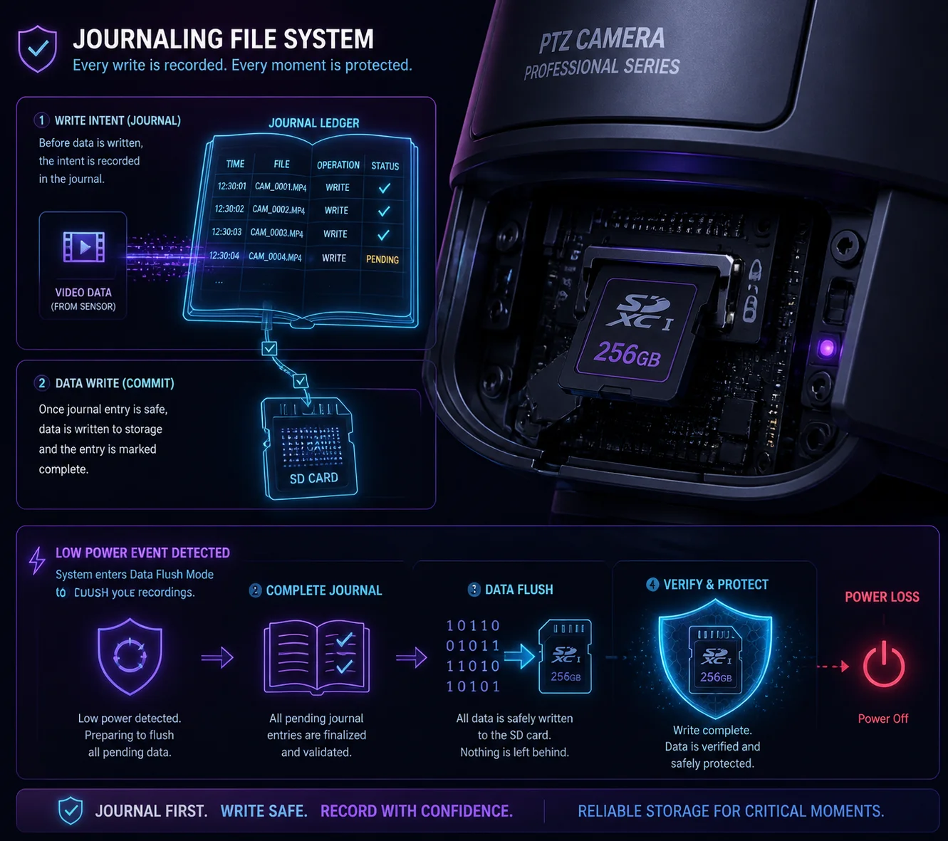 file system protection low power crash sd card
Why Power Loss Corrupts Files
To understand the protection, you first need to understand the problem. When a camera records video, it does not write data directly to the SD card byte by byte. It uses a write buffer — a chunk of RAM that collects data and then writes it to the card in large blocks. This is faster and extends the SD card’s lifespan.
But here is the risk: if power dies while the buffer is half-written, the file on the SD card is incomplete. The file system’s directory table says “this file is 50MB” but only 30MB actually made it to the card. Now the file is corrupted. Worse, the directory table itself might be corrupted, which can make the entire card unreadable.
The Three Layers of Protection
Layer 1: Early warning from BMS. The BMS does not wait until the battery is completely dead to warn the camera. It sends a “low voltage alert” signal to the MCU when the battery hits a pre-warning threshold (say, 11.5V). This gives the firmware time — usually several minutes — to finish its current write operation and prepare for shutdown.
Layer 2: Controlled shutdown sequence. When the firmware receives the low-voltage alert, it does the following:
- Stops accepting new recording segments.
- Flushes all write buffers to the SD card.
- Closes all open file handles.
- Updates the file system journal (a log of recent changes).
- Sends a “going offline” message to the cloud.
- Signals the PMU that it is safe to cut power.
This is called a “graceful shutdown.” It is the same concept as clicking “Shut Down” on your laptop instead of pulling the power cord.
Layer 3: Journaling file system. Even if the graceful shutdown fails (say, the voltage drops faster than expected), the journaling file system provides a safety net. A journal is like a checklist. Before the system writes data, it first writes a note in the journal: “I am about to write block X to file Y.” After the write completes, it marks the journal entry as “done.”
If power dies mid-write, the journal still has the incomplete entry. On the next boot, the file system reads the journal, sees the incomplete operation, and rolls it back. The file might be shorter than expected, but the file system itself stays intact. You do not lose the entire card.
For more detail, read this explanation of journaling file systems (ext4, F2FS) 5.
What About the PTZ Preset Position?
This is a detail many people overlook. If the camera loses power while the PTZ motor is moving, the motor stops at a random position. On reboot, the camera does not know where it is pointing.
Good PTZ cameras solve this with one of two methods:
- Absolute encoders: The motor has a position sensor that remembers its angle even without power. On boot, the camera reads the encoder and knows exactly where it is.
- Home position calibration: On boot, the PTZ runs a quick calibration routine — it moves to a known reference point (like full left and full down), then moves to the saved preset. This takes a few extra seconds but ensures accuracy.
Either way, the camera returns to its correct position automatically. The user sees the same view he configured, every time the system wakes up.
Learn more about absolute vs incremental encoders for PTZ motors 6.
Conclusion
A properly designed 4G solar PTZ system sleeps, wakes, reconnects, and recovers on its own — no human needed. Ask your supplier for their low-power white paper, verify the hysteresis logic, and you will cut site visits by over 95%.
1. Battery University guide to Li-ion over-discharge damage. ↩︎ 2. Technical overview of BMS low-voltage disconnect circuits. ↩︎ 3. How MPPT charge controllers manage battery recovery hysteresis. ↩︎ 4. Embedded design guide to hardware watchdog implementation. ↩︎ 5. Linux kernel documentation on ext4 journaling mechanism. ↩︎ 6. Difference between absolute and incremental motor encoders. ↩︎