
I have seen too many laser PTZ cameras fail at night. The laser lights up the center, but the edges go completely dark. This “flashlight effect” ruins the whole image and makes the camera useless for real security work.
The laser beam synchronizes with the 40X zoom lens through a DSS (Digital Synchronization System). This system uses stepper motors inside the laser module to physically adjust the beam’s spread angle in real time. As the lens zooms in, the laser narrows. As the lens zooms out, the laser widens. The control board reads the zoom motor’s pulse position and maps it to the correct laser angle using a pre-calibrated curve.
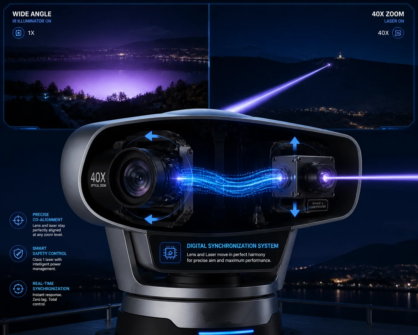 laser beam synchronization with 40X zoom PTZ camera
In this article, I will break down exactly how this synchronization works. I will cover the automatic narrowing mechanism, the anti-overexposure logic, the manual override options, and the re-alignment speed after preset calls. If you are sourcing laser PTZ cameras from China, this is the technical knowledge you need before signing any purchase order.
Table of Contents
Will the Laser Beam Automatically Narrow Its Focus as I Zoom Into 40X?
I used to think the laser just stayed at one fixed angle. I was wrong. The first time I saw a properly synced laser PTZ, I realized how much technology sits behind that smooth transition.
Yes, the laser beam automatically narrows as you zoom into 40X. A micro stepper motor inside the laser module moves a diverging lens forward or backward. At 1X wide angle, the laser spreads to about 20°–60°. At 40X telephoto, it compresses down to less than 1°, focusing all energy into a tight beam that can reach 500 meters or more.
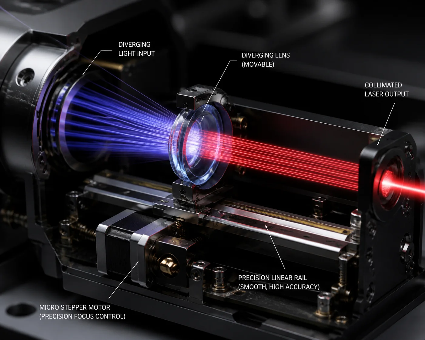 laser beam narrowing at 40X zoom PTZ camera
How the Stepper Motor Drive Works
The laser module is not a simple fixed light source. Inside, there is a small optical assembly with its own set of lenses. A stepper motor 1 moves these lenses along a rail. When the camera’s main control board sends a zoom command to the camera lens, it also sends a synchronized command to the laser motor.
This electromechanical synchronization is known as master-slave control 2 in motion control systems.
Here is the basic flow:
- You press “zoom in” on your joystick or NVR.
- The control board sends pulses to the camera’s zoom motor.
- At the same time, the board sends pulses to the laser’s stepper motor.
- The laser lens moves forward, compressing the beam.
- The diverging lens 3 mechanics adjust the beam angle.
This happens simultaneously. The laser does not wait for the zoom to finish. Both motors move together.
The FOV-to-Laser Curve
The relationship between zoom level and beam angle is not linear. A 2X zoom does not mean the laser angle cuts in half. The actual curve depends on the lens design. Our R&D team calibrates each lens model and creates a field of view calibration curve 4 stored in the control board’s firmware.
| Zoom Level | Approximate Camera FOV | Laser Beam Angle |
|---|---|---|
| 1X (6.4 mm) | ~60° | 18°–20° |
| 10X (64 mm) | ~6° | 4°–5° |
| 20X (128 mm) | ~3° | 1.5°–2° |
| 40X (256 mm) | ~1.5° | 0.5°–0.8° |
The control board reads the zoom motor’s pulse count. It then looks up the correct laser angle from this table. The result is a smooth, continuous adjustment. The laser beam always covers the camera’s field of view with about 10% extra margin on each side. This margin prevents hard dark edges in the image.
Why This Matters for Long-Range Surveillance
At 40X, the camera’s field of view is extremely narrow. If the laser stayed at a wide angle, most of the laser energy would be wasted outside the frame. The image would be dim and noisy. By compressing all the laser power into a tight beam, the system pushes usable illumination out to 500 meters, 800 meters, or even further. This is why a 5W laser with proper synchronization can outperform a 20W IR LED array at long range. The energy goes exactly where the camera is looking. Nothing is wasted.
How Does the “Zoom-Laser Sync” Technology Eliminate the Overexposure of Nearby Objects?
I have dealt with customer complaints about “white faces” in night footage. The person walks close to the camera, and the laser blasts them with full power. The image is completely blown out. This is a real problem, and it costs integrators their reputation.
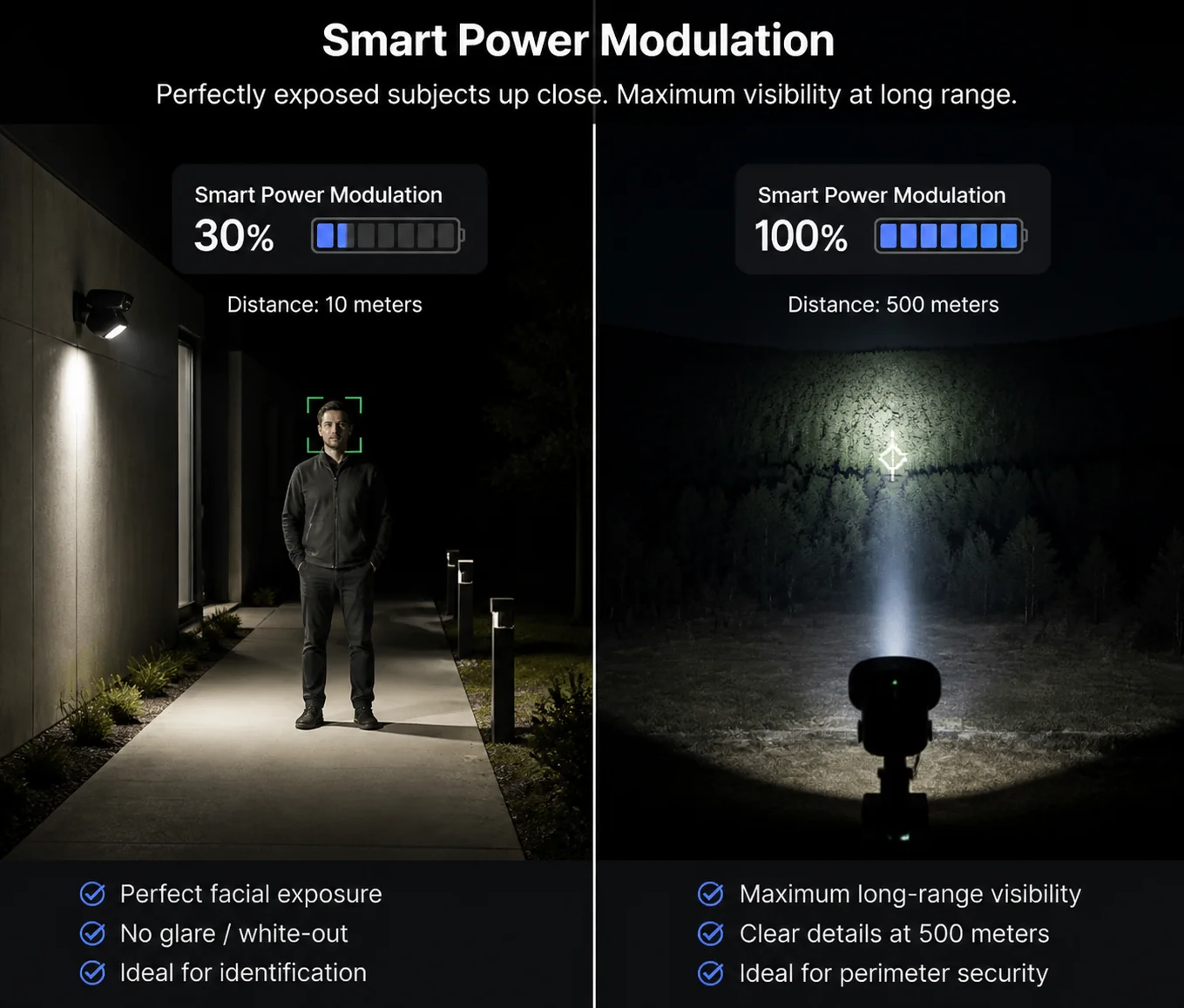
The system eliminates overexposure through smart intensity control. When the lens is at wide angle (short range), the control board automatically reduces the laser’s output power. When the lens zooms to 40X (long range), the laser ramps up to full power. This prevents nearby objects from being washed out while still delivering maximum illumination at distance.
 zoom laser sync anti-overexposure PTZ camera
The Two Layers of Overexposure Prevention
There are two separate mechanisms working together. The first is the beam angle adjustment I described above. The second is power modulation. Both are controlled by the same board, but they serve different purposes.
Layer 1: Beam Angle Adjustment
When the lens is at wide angle, the laser spreads its energy across a large area. This naturally reduces the intensity per square meter. Think of it like a garden hose. A wide spray pattern delivers less water pressure to any single spot. The same principle applies to the laser beam.
Layer 2: Power Modulation (PWM Control)
Even with a wide beam, a high-power laser can still overexpose nearby objects. So the control board also adjusts the laser’s drive current using PWM (Pulse Width Modulation) 5. At close range, the laser might operate at only 30%–50% of its maximum power. At full 40X zoom, it runs at 100%.
| Scenario | Beam Angle | Laser Power | Purpose |
|---|---|---|---|
| Wide angle, close target (< 50m) | 18°–20° | 30%–40% | Prevent face/object overexposure |
| Mid zoom, medium target (50–200m) | 3°–5° | 60%–80% | Balanced illumination |
| 40X zoom, far target (200–800m) | 0.5°–0.8° | 100% | Maximum penetration and range |
How the Camera’s AGC Cooperates With the Laser
The camera’s image sensor also plays a role. AGC (Automatic Gain Control) 6 and AE (Auto Exposure) adjust the sensor’s sensitivity based on the incoming light. But relying only on AGC creates grainy images. The better approach is to control the light source itself. That is why the laser power modulation is so important. It gives the sensor a clean, well-balanced input signal. The AGC then only needs to make minor adjustments instead of fighting against a wildly uneven light source.
Real-World Impact
I have seen projects where the integrator installed a cheap laser PTZ without power modulation. The camera worked fine at 300 meters. But when a security guard walked within 20 meters of the camera at night, the guard’s face was a white blob. The client rejected the installation. The integrator had to replace all 12 cameras. That is the kind of cost that proper zoom-laser sync technology prevents. Our cameras at Loyalty-Secu include both beam angle sync and power modulation as standard features on every laser PTZ model.
Is There a Manual Override to Adjust the Laser Beam Width Independently of the Zoom?
I get this question a lot from experienced integrators. They want full control. They do not want the camera making all the decisions for them. And I understand that. Some scenes are not standard. Sometimes you need to override the automatic system.
Yes, most professional-grade laser PTZ cameras offer a manual override. You can adjust the laser beam width, power level, and even the beam’s center offset independently of the zoom position. This is typically done through the camera’s OSD menu, web interface, or via Pelco-D/ONVIF commands from the NVR.
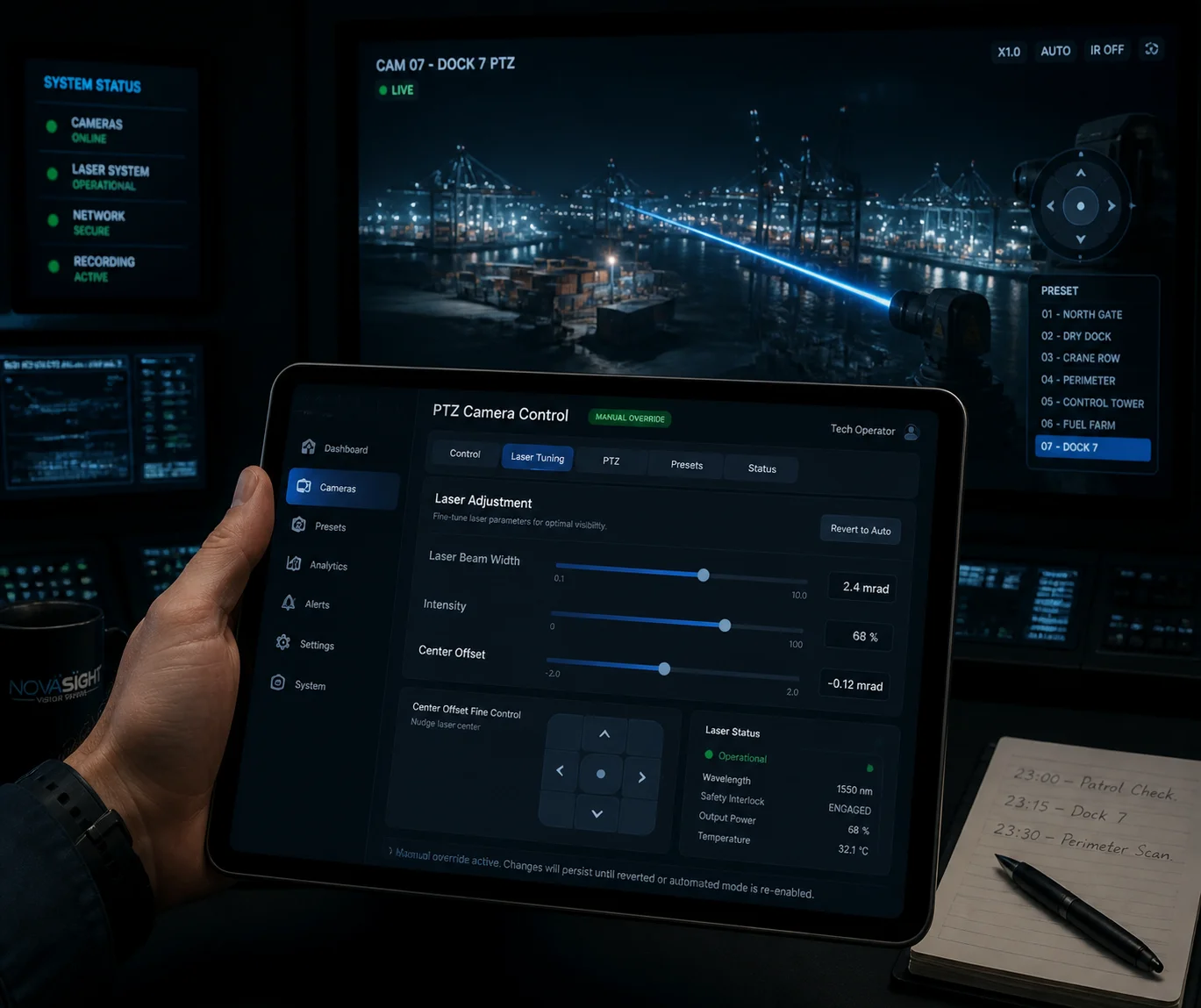 manual override laser beam width PTZ camera
When You Need Manual Override
The automatic sync works well for 90% of scenes. But there are edge cases where manual control is necessary.
Case 1: Uneven Terrain Imagine a camera mounted on a hilltop looking down at a valley. The left side of the frame is 100 meters away. The right side is 400 meters away. The automatic system assumes a uniform distance. But in this scene, the left side will be overexposed while the right side is too dark. An experienced operator might want to narrow the beam slightly and shift it toward the far side.
Case 2: Reflective Surfaces Water, glass, and metal surfaces reflect laser light back into the sensor. This creates hot spots. A manual power reduction can fix this without changing the zoom level.
Case 3: Covert Surveillance Some operators want the laser at minimum power to reduce the visible glow of the IR beam. Even though 808nm and 850nm lasers are “invisible” to the naked eye, they still produce a faint red glow that trained observers can spot. Reducing power manually helps in covert operations.
What You Can Typically Adjust
Here is what our Loyalty-Secu laser PTZ cameras allow you to control manually:
- Laser ON/OFF: Turn the laser completely off and rely on ambient light or IR LEDs only.
- Beam Width: Override the automatic angle and set a fixed divergence angle.
- Power Level: Set the laser to a fixed percentage (e.g., 20%, 50%, 80%, 100%).
- Center Offset Compensation: Shift the laser beam’s center point left, right, up, or down by small increments. This is critical if the beam drifts off-center after installation. This is often called beam drift correction 7.
- Auto/Manual Mode Toggle: Switch between fully automatic sync and full manual control with one command.
How to Access Manual Override
Most systems support three access methods:
| Access Method | Best For | Notes |
|---|---|---|
| OSD Menu (on-screen display) | Field technicians during installation | Navigate with joystick, no network needed |
| Web Interface (browser) | Remote system administrators | Full parameter control with visual feedback |
| Pelco-D 8 / ONVIF commands | NVR/VMS integration | Scriptable, can be automated by the VMS |
The key point is this: automatic sync should be the default. Manual override is the safety net. A good laser PTZ gives you both. If a supplier tells you “it is fully automatic, no manual control,” that is a red flag. You want the option to fine-tune, especially on complex projects.
What Is the Response Time for the Laser to Re-Align After a Rapid Preset Call?
I have tested many PTZ cameras where the laser takes 2–3 seconds to catch up after a preset call. During those seconds, the image is either overexposed or completely dark. For a security application, 3 seconds of blindness is unacceptable.
On a well-engineered laser PTZ, the laser re-aligns within 200–500 milliseconds after a rapid preset call. The control board pre-loads the target laser parameters (beam angle and power) for each preset position. So when the PTZ moves to a preset, the laser motor starts adjusting simultaneously with the pan/tilt/zoom motors, not after them.
![]() laser re-alignment response time PTZ preset call
laser re-alignment response time PTZ preset call
Why Preset Calls Are the Hardest Test
A preset call is the most demanding scenario for laser synchronization. Here is why:
During normal zooming, the lens moves slowly and smoothly. The laser motor can easily keep up. But a preset call changes everything at once. The pan motor spins. The tilt motor tilts. The zoom motor jumps from one focal length to another. All of this happens in under one second. The laser system must also jump from its current angle and power to a completely different set of parameters.
For example, Preset 1 might be: Pan 45°, Tilt -10°, Zoom 5X, Laser angle 10°, Laser power 40%. Preset 2 might be: Pan 180°, Tilt -30°, Zoom 40X, Laser angle 0.5°, Laser power 100%.
The system must transition between these two states as fast as possible.
How We Achieve Fast Re-Alignment
The secret is pre-stored laser parameters per preset. This is a form of preset synchronization technique 9. When you save a preset position, the control board does not just save pan, tilt, and zoom values. It also saves the corresponding laser beam angle and power level. When the preset is called, all five parameters are sent to their respective motors at the same time.
Here is the sequence:
- Operator calls Preset 2.
- Control board reads stored values: Pan 180°, Tilt -30°, Zoom 40X, Laser angle 0.5°, Power 100%.
- All motors receive their commands simultaneously.
- Pan/tilt motors begin moving (typical travel time: 1–3 seconds depending on distance).
- Zoom motor begins moving (typical travel time: 0.5–2 seconds).
- Laser stepper motor begins moving (typical travel time: 200–500 milliseconds).
- The laser arrives at its target angle before the pan/tilt even finishes moving.
This means by the time the camera settles on the new scene, the laser is already correctly configured. There is no visible lag.
What Causes Slow Re-Alignment in Cheap Systems
In low-cost laser PTZ cameras, the laser parameters are not pre-stored per preset. Instead, the system works like this:
- PTZ moves to the preset position.
- PTZ finishes moving and reports the new zoom level.
- Only then does the control board calculate the laser angle.
- The laser motor starts moving.
This sequential approach adds 1–3 seconds of delay. During that time, the laser is at the wrong angle. The image looks terrible. If you are evaluating a supplier, ask them to demonstrate a rapid preset call sequence. Watch the transition carefully. If you see a flash of overexposure or a moment of darkness between presets, the synchronization is not truly simultaneous.
Factory Calibration and Optical Axis Alignment
Fast response time means nothing if the laser beam is not centered on the image. At our factory in Shenzhen, every 40X laser PTZ goes through an optical axis alignment process. We use a laser collimator 10 to align the laser emitter’s axis with the camera lens axis. The tolerance is 0.01° or better.
For high-end models, we also offer firmware-based Center Offset Compensation. If the beam drifts slightly after shipping or installation, the integrator can adjust the laser motor’s home position through the web interface. This gives pixel-level centering without opening the housing.
Conclusion
The laser beam in a 40X PTZ camera synchronizes through stepper motors, real-time pulse mapping, and factory-calibrated optical alignment. It is precise engineering, not magic. Ask your supplier to prove it with a live demo.
1. Stepper motor control for laser zoom synchronization. ↩︎ 2. Master-slave control in motion synchronization systems. ↩︎ 3. Diverging lens mechanics for laser beam angle adjustment. ↩︎ 4. Field of view to laser angle calibration curves. ↩︎ 5. PWM current control for laser power modulation. ↩︎ 6. AGC/AE interaction with variable-intensity IR illumination. ↩︎ 7. Beam drift correction for laser center offset. ↩︎ 8. Pelco-D protocol for PTZ manual override commands. ↩︎ 9. Pre-stored preset parameter synchronization technique. ↩︎ 10. Optical axis alignment using laser collimator tools. ↩︎