
I have seen too many off-grid cameras go silent in the field. The root cause was not the network. It was the SIM card losing contact inside the slot.
A hardware-level SIM detection circuit1 uses a physical detection pin, RC debounce filtering, TVS voltage protection, and auto-healing firmware logic2 to sense card status in real time. These four layers work together to stop the system from misreading a brief vibration as a full SIM removal, which prevents unnecessary disconnections and keeps the 4G link alive.
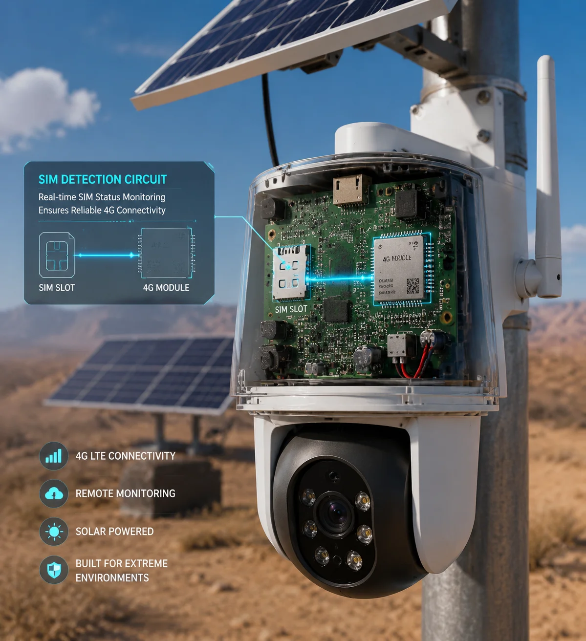 Hardware SIM detection circuit in PTZ camera preventing disconnections
In remote solar-powered deployments across North America, the Middle East, and rural Europe, a single false “SIM Removed” event can trigger a full module restart. That means minutes of downtime. For a system integrator billing clients on uptime SLAs, minutes cost money. Below, I will walk through the four most common questions my clients ask about this circuit and explain exactly how each protection layer works at the board level.
Table of Contents
Will the Camera Immediately Notify Me if the SIM Card Loses Contact Due to High-Frequency Vibration?
I once had a client in Texas who mounted cameras on highway light poles. Every time a heavy truck passed, the camera dropped offline for 30 seconds. The SIM card was fine. The slot was the problem.
Yes. Industrial PTZ cameras with a mechanical detection pin on the SIM slot can sense card displacement within milliseconds. The detection pin sends a voltage-level change to the 4G module’s SIM_DET GPIO3, and the system logs the event and triggers an alert before the network layer even notices a packet loss.
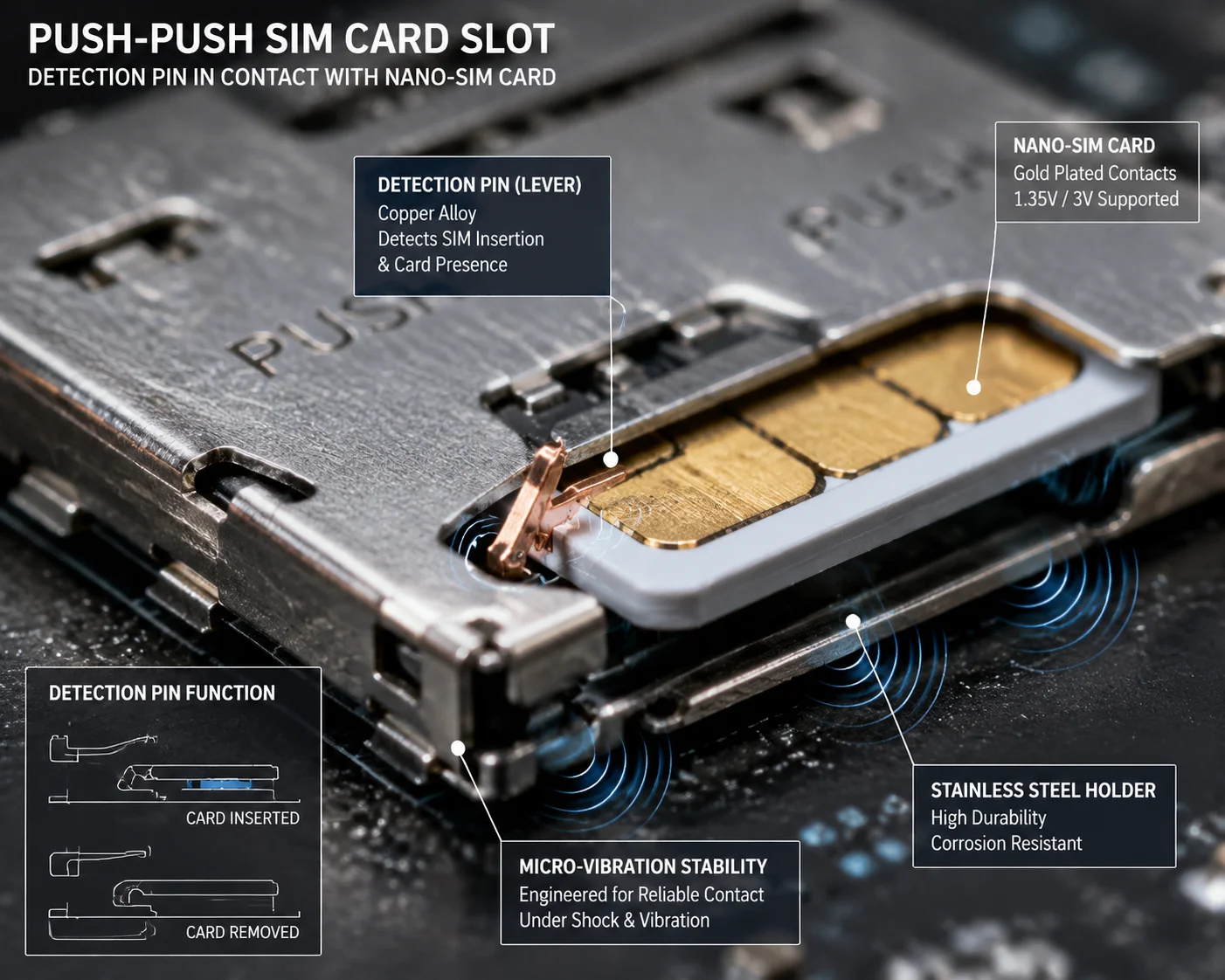 SIM card mechanical detection pin in industrial PTZ camera slot
How the Mechanical Detection Pin Works
Inside an industrial-grade SIM card slot, there is a tiny metal lever called a detection pin4. This is not a software feature. It is a physical switch built into the card holder.
When you push a SIM card fully into the slot, the card body presses down on this metal lever. The lever closes a circuit between the SIM_DET pin and ground. This sends a clear low-voltage signal to the 4G module. The module reads this signal and knows: “The card is seated.”
If the card shifts even slightly — say, 0.3 mm due to vibration — the lever springs back. The voltage on SIM_DET jumps high. The module detects this change in under 5 milliseconds.
What Happens After Detection
The system does not just detect the change. It acts on it. Here is the typical response chain:
| Step | Action | Time |
|---|---|---|
| 1 | Detection pin opens due to card shift | < 5 ms |
| 2 | RC filter smooths the signal to avoid false trigger | 10–50 ms |
| 3 | Firmware samples the SIM_DET pin multiple times | 200–500 ms |
| 4 | If signal stays abnormal, system logs “SIM Unstable” | ~ 1 s |
| 5 | System sends alert via secondary channel (if available) or stores the event locally | ~ 2 s |
The key point here is that the camera does not wait for the network to fail. It does not wait for packet loss or a timeout from the carrier. It catches the problem at the physical layer, before the 4G module even tries to re-register.
Why This Matters for Pole-Mounted and Vehicle-Mounted Cameras
Pole-mounted cameras in windy areas can experience sustained vibration at 5–15 Hz. Vehicle-mounted units on construction equipment face random shocks up to 5G. In both cases, a standard consumer-grade SIM slot with friction-only retention will fail. The card will micro-shift, the contacts will bounce, and the module will cycle through “SIM inserted → SIM removed → SIM inserted” loops.
An industrial push-push SIM slot5 with a detection pin solves this. The pin gives the system a binary, hardware-level answer: the card is either fully seated or it is not. There is no gray area. And because the detection happens at the electrical level, the system can respond faster than any software-only polling method.
If your supplier cannot tell you whether their SIM slot has a mechanical detection pin, that is a red flag. Ask for the slot datasheet. Look for the CD or DET pin in the pinout diagram.
How Does the “Hot Swap” Detection Prevent the Module’s Firmware from Hanging During Card Re-Insertion?
I have tested dozens of 4G modules from different chipset vendors. Some of them freeze completely when you pull and re-insert a SIM card while the module is powered on. The firmware just hangs.
A properly designed hot-swap detection6 circuit cuts SIM power (VSIM) the moment the detection pin opens, then re-initializes the SIM interface cleanly when the card is re-inserted. This controlled power cycle prevents the 4G module from entering a locked state, and the firmware uses AT commands like AT+CFUN=1,1 to force a clean network re-registration without rebooting the entire camera.
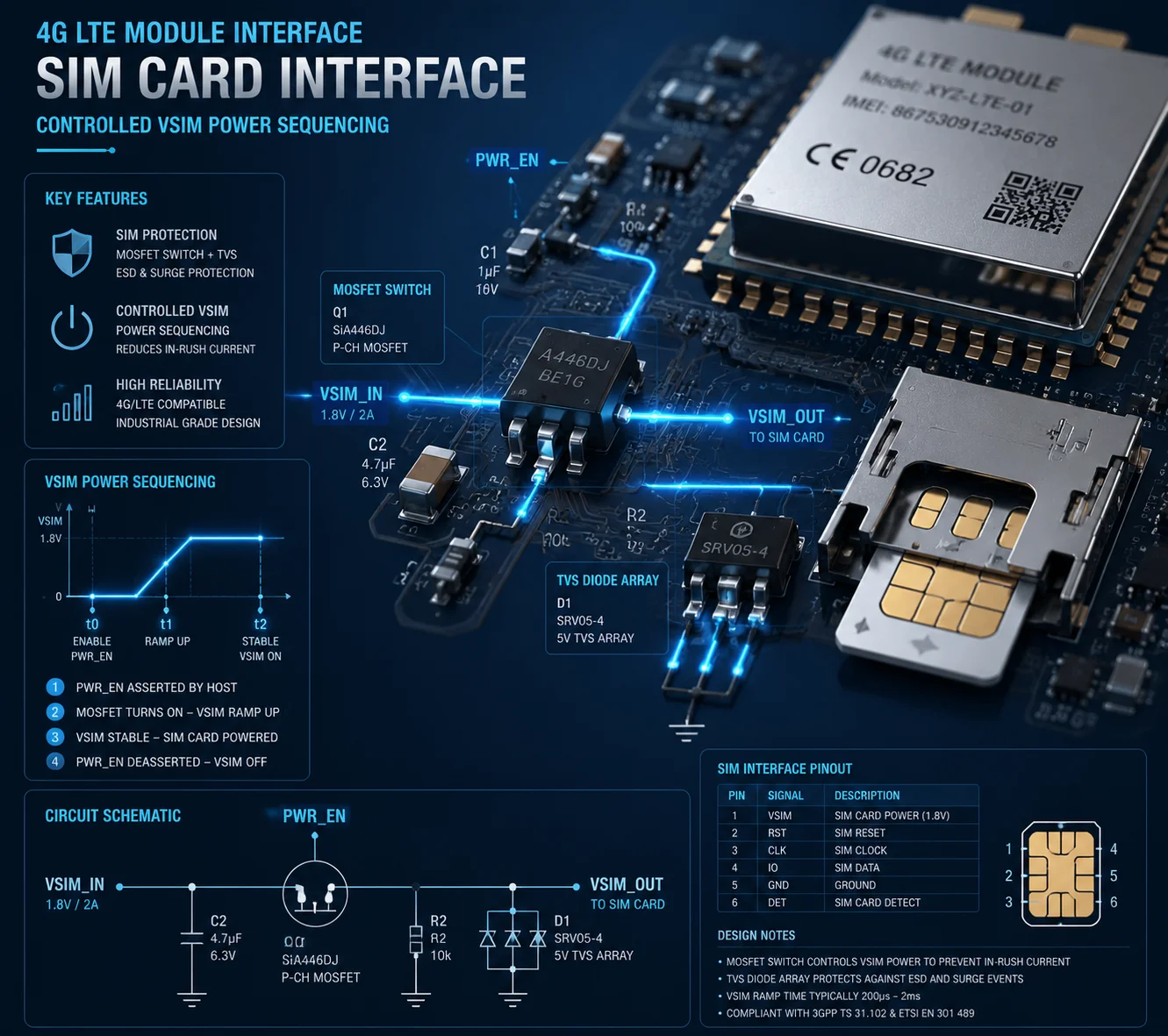 Hot swap SIM detection circuit preventing firmware hang in 4G module
Why Firmware Hangs Happen in the First Place
When a SIM card is pulled out while the 4G module is actively communicating with it, the data line (SIM_DATA) and clock line (SIM_CLK) are suddenly interrupted mid-transaction. The module’s SIM controller is waiting for a response that will never come. Depending on the chipset, this can cause:
- A timeout loop where the controller keeps retrying the same command
- A register lockup where the SIM interface state machine gets stuck
- A full module crash that requires a hardware reset
This is not a rare edge case. It happens regularly in the field when maintenance workers swap SIM cards without powering down the camera first. It also happens when vibration causes a momentary card disconnect that lasts just long enough to corrupt a SIM transaction.
The Hardware Solution: Controlled Power Sequencing
The hardware-level fix is a power control circuit on the VSIM line. Here is how it works:
-
Instant power cut on removal. When the detection pin opens, a MOSFET switch on the
VSIMline cuts power to the SIM card within microseconds. This forces the SIM controller to recognize a clean removal, not a corrupted transaction. -
Delayed power restore on re-insertion. When the detection pin closes again (card re-inserted), the circuit waits approximately 100–200 ms before restoring
VSIMpower. This delay gives the card time to settle in the slot and ensures all contact pins are making solid connection before the module tries to communicate. -
Firmware re-initialization. After
VSIMis restored, the firmware sends anAT+CFUN=1,17 command to the module. This forces a full RF and SIM re-initialization without rebooting the camera’s main processor. The module re-reads the SIM, re-registers with the carrier, and resumes data transmission.
TVS Protection During Hot Swap
The moment a SIM card is pulled from a live slot, there is a risk of electrostatic discharge (ESD) and voltage spikes on the contact pins. A TVS (Transient Voltage Suppressor) diode array on the SIM signal lines clamps these spikes to safe levels.
| SIM Signal Line | TVS Clamp Voltage | Max Capacitance Allowed |
|---|---|---|
| SIM_VCC (VSIM) | 3.6 V | N/A |
| SIM_DATA | 3.6 V | ≤ 10 pF |
| SIM_CLK | 3.6 V | ≤ 10 pF |
| SIM_RST | 3.6 V | ≤ 15 pF |
| SIM_DET (CD) | 3.6 V | ≤ 50 pF |
The capacitance limit is critical. If the TVS diode has too much parasitic capacitance, it will distort the SIM clock signal and cause communication errors. This is a common mistake in cheap camera designs — they use generic TVS arrays meant for USB lines, which have 50–100 pF capacitance. That is far too high for SIM interfaces.
What to Ask Your Supplier
Ask whether the camera supports live SIM card replacement without a full reboot. If the answer is yes, ask how. If they say “the firmware handles it,” push further. Ask whether there is a hardware power switch on the VSIM line. A firmware-only solution without hardware power sequencing is unreliable. The module will eventually hang during a hot swap under field conditions.
Is There a Debounce Circuit to Filter Out False “SIM Removed” Signals in Industrial Environments?
I learned this lesson the hard way. A batch of cameras we shipped to a mining site in Canada kept logging “SIM Removed” events every few hours. The SIM cards were fine. The slots were fine. The problem was electrical noise from nearby heavy machinery coupling into the SIM detection line.
Yes. Industrial-grade PTZ cameras use an RC (resistor-capacitor) low-pass filter on the SIM detection line, often combined with a Schmitt trigger input8, to filter out false signals caused by vibration, EMI, or thermal expansion. The debounce window is typically 200 ms to 1 second, meaning the system ignores any card-status change shorter than this threshold.
 RC debounce circuit filtering false SIM removed signals in industrial camera
Understanding the Noise Problem
In a clean lab environment, the SIM detection signal is a perfect square wave: low when the card is in, high when the card is out. In the real world, this signal looks nothing like a square wave.
Vibration causes the detection pin to bounce. Temperature changes cause the SIM card to expand or contract slightly, changing contact pressure. Electromagnetic interference from motors, inverters, or nearby radio transmitters induces voltage spikes on the detection line. All of these create short, random pulses on the SIM_DET signal that look like card removal events to the 4G module.
Without filtering, the module would react to every single pulse. It would try to de-register from the network, cut SIM power, wait, re-power, re-initialize, and re-register. This cycle takes 10–30 seconds each time. If it happens every few minutes, the camera is effectively useless.
How the RC Filter Works
The hardware fix is simple and elegant. A resistor (typically 10 kΩ) and a capacitor (typically 0.1 µF) are placed on the SIM_DET line. Together, they form a low-pass filter with a time constant of:
τ = R × C = 10,000 Ω × 0.0000001 F = 0.001 seconds = 1 ms
This means any pulse shorter than about 1 ms is smoothed out and never reaches the module’s GPIO pin. The capacitor absorbs the spike, and the resistor limits the charging current.
For more aggressive filtering in high-vibration environments, designers increase the capacitor to 1 µF or even 10 µF, pushing the time constant to 10–100 ms. This makes the circuit ignore even longer disturbances.
The Schmitt Trigger Layer
After the RC filter, the signal may still have a slow rise or fall time. A slow-changing voltage near the logic threshold can cause the digital input to oscillate — reading high, then low, then high again in rapid succession. This is called “metastability9“.
A Schmitt trigger input solves this. It has two different threshold voltages: one for the rising edge (say, 2.0 V) and one for the falling edge (say, 0.8 V). The signal must cross the upper threshold to be read as high, and it must drop below the lower threshold to be read as low. Any voltage between 0.8 V and 2.0 V is ignored.
This hysteresis band eliminates the oscillation problem completely. The output of the Schmitt trigger is always a clean, sharp digital signal, regardless of how noisy the input is.
Firmware Debounce on Top of Hardware Filtering
Even with RC filtering and Schmitt triggering, the firmware adds one more layer. It samples the SIM_DET pin at regular intervals (typically every 10–50 ms) and requires a consistent reading for a set number of consecutive samples before changing the card status.
For example, if the firmware samples every 20 ms and requires 25 consecutive “card removed” readings, the effective debounce window is 500 ms. Any disturbance shorter than 500 ms is completely invisible to the system.
This three-layer approach — RC filter, Schmitt trigger, firmware sampling — is what separates an industrial camera from a consumer device. Consumer devices might have one of these layers. Industrial cameras need all three.
Does the SIM Slot Have a Protective Cover to Prevent Unauthorized Removal in Public Areas?
I get this question from every client who deploys cameras in public spaces. Schools, parking lots, city intersections. If someone can reach the camera, they will try to open it.
Industrial PTZ cameras designed for public deployment use tamper-resistant SIM compartments10 with screw-locked covers, recessed slot positions inside sealed housings, and in some cases, software-level SIM lock features that bind the module to a specific SIM card’s ICCID. This combination of physical and logical protection prevents both accidental and intentional SIM removal.
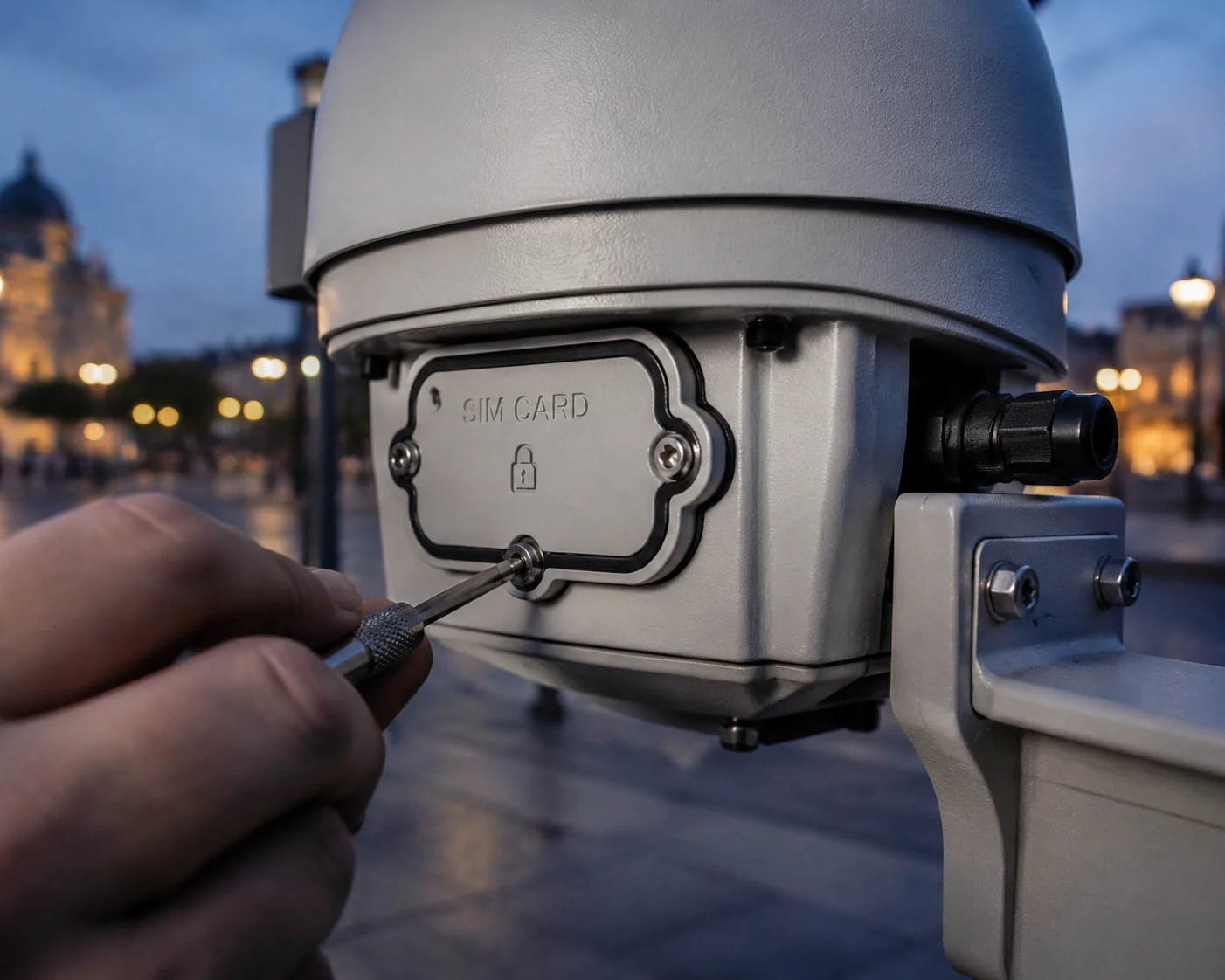 Tamper-resistant SIM slot with protective cover in public area PTZ camera
Physical Protection: More Than Just a Cover
A simple rubber flap over the SIM slot is not enough for public deployments. Here is what a properly designed system looks like:
The SIM card slot is located inside the camera’s main housing, not on an external panel. To access it, you must remove the camera from its mount and open a sealed compartment that requires a specific tool — usually a hex key or a proprietary security screw. The compartment itself is part of the IP66/IP67 sealed enclosure, so opening it also breaks the weather seal. This means any tampering is immediately visible during routine inspection.
Logical Protection: SIM Lock and ICCID Binding
Physical barriers can be defeated with enough time and tools. So the firmware adds a second layer. The 4G module can be configured to accept only a specific SIM card, identified by its ICCID (Integrated Circuit Card Identifier). If someone removes the original SIM and inserts a different one, the module refuses to register on the network.
This feature is configured via AT commands during initial setup:
| Feature | AT Command Example | Purpose |
|---|---|---|
| Read current ICCID | AT+CCID | Get the SIM card’s unique ID |
| Lock to specific ICCID | AT+CLCK="SC",1,"PIN" | Prevent use with unauthorized SIM |
| Auto-reject foreign SIM | Firmware-level config | Module ignores SIM cards not matching stored ICCID |
Why This Matters for System Integrators
If you are a system integrator deploying 200 cameras across a city, SIM card theft is a real operational risk. Each SIM card has a data plan. If someone steals a SIM and uses it in a personal device, you are paying for their data. Worse, if they insert a different SIM into your camera, your monitoring platform loses that camera entirely.
The combination of physical tamper resistance and ICCID binding eliminates both risks. The physical barrier slows down the attacker. The logical lock makes the stolen SIM useless and the camera immune to foreign SIMs.
Integration with Tamper Alarms
Some advanced PTZ cameras also include a tamper detection switch inside the housing. When the housing is opened, the switch triggers an alarm event that is sent to the VMS (Video Management System) or directly to the operator’s phone via SMS or push notification. This gives you real-time awareness of any physical tampering attempt, even if the camera is in a remote location.
At Loyalty-Secu, we design our housings with these tamper switches as standard on all models intended for public deployment. The switch is wired directly to the main board’s GPIO, so it works independently of the camera’s video processing pipeline. Even if the camera’s software crashes, the tamper alarm still fires.
Conclusion
A reliable SIM detection circuit combines mechanical pin sensing, RC debounce filtering, TVS protection, and firmware auto-healing to keep your 4G PTZ camera online in any environment.
1. Understand the four-layer architecture of a hardware SIM detection circuit that prevents accidental disconnections. ↩︎ 2. Firmware logic that re-initializes the SIM interface after a controlled power sequence, preventing module hangs. ↩︎ 3. The dedicated GPIO pin on the 4G module that reads the SIM detection pin status. ↩︎ 4. Learn how the mechanical detection pin inside a SIM card slot provides a binary, hardware-level card presence signal. ↩︎ 5. An industrial SIM card connector design with push-push insertion and mechanical retention, often including a detection pin. ↩︎ 6. A circuit that cuts SIM power on removal and re-initializes cleanly on re-insertion to prevent firmware hangs. ↩︎ 7. AT command that forces a full RF and SIM re-initialization without a main processor reboot. ↩︎ 8. A comparator with hysteresis that cleans up slow or noisy digital signals from the RC filter output. ↩︎ 9. A condition where a digital input oscillates near the logic threshold, causing erratic readings; prevented by Schmitt triggers. ↩︎ 10. Physical design features such as screw-locked covers and recessed slots that deter unauthorized SIM removal. ↩︎