
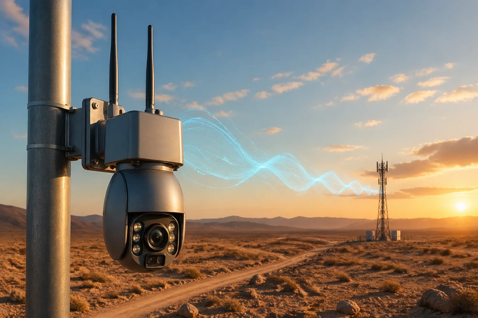
I have seen too many PTZ cameras lose connection in the field. One antenna is not enough when your site is miles from the nearest cell tower.
A dual-antenna design improves signal coverage in remote areas by using space diversity and MIMO technology 1. Two antennas receive signals from different paths, reduce fading, and increase data throughput. This keeps your PTZ camera connected and streaming even at the edge of cellular or Wi-Fi coverage.
 dual antenna PTZ camera signal coverage remote areas
In this article, I break down exactly how dual antennas work in real-world deployments. I cover external antenna options, MIMO speed gains, interference resistance, and proper antenna spacing. If you are sourcing 4G solar PTZ cameras from China for remote projects, this is information you need before placing your next order.
Can I Use a High-Gain External Yagi Antenna with the Secondary Antenna Port?
I get this question a lot from system integrators working in rural America. Their sites are far from base stations, and the built-in antennas are not enough.
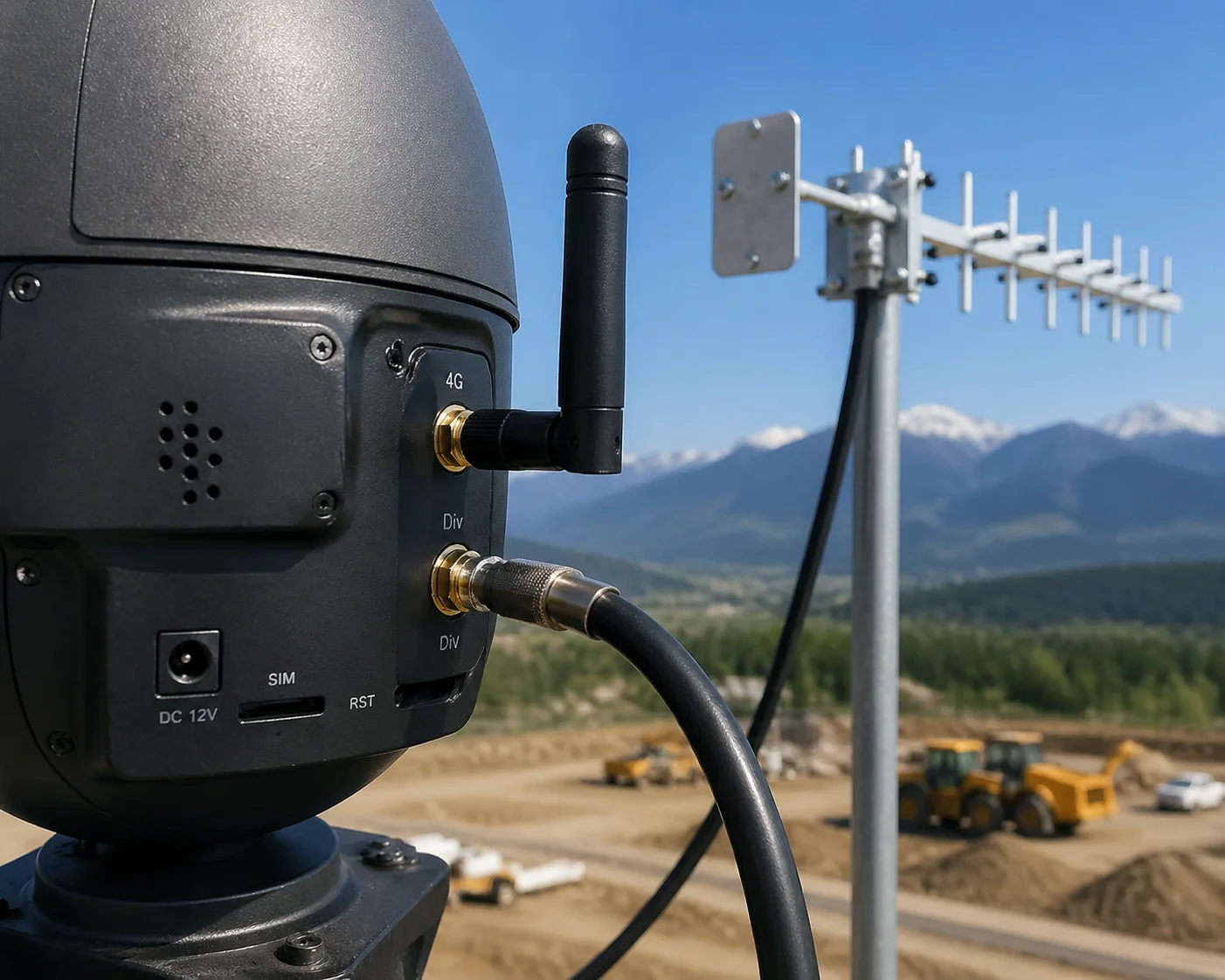
Yes, most industrial-grade 4G PTZ cameras with true dual-antenna design have two RF ports — Main and Div — using standard SMA or TS9 connectors. You can connect a high-gain external Yagi antenna 2 to the secondary port to boost receive sensitivity and extend your usable range by 15% to 25%.
 high gain Yagi antenna secondary port 4G PTZ camera
Why the Secondary Port Matters
Many people think the secondary antenna port is just a backup. It is not. In a real dual-antenna system, the 4G module inside the camera has two separate RF chains. One connects to the Main port. The other connects to the Div (diversity) port. Both are active at the same time.
When I connect a high-gain Yagi antenna to the secondary port, I am giving the diversity receiver a stronger signal to work with. The system then combines both signals. This is called Maximum Ratio Combining (MRC). The result is a higher effective signal-to-noise ratio (SNR).
What Kind of Yagi Antenna Should I Use?
For 4G LTE bands commonly used in the US (Band 12, Band 13, Band 71), I recommend a directional Yagi antenna with at least 10 dBi gain. Point it toward the nearest cell tower. This setup can turn a marginal connection into a usable one.
Here is a quick comparison:
| Antenna Type | Typical Gain | Beam Width | Best Use Case |
|---|---|---|---|
| Built-in Omni (stock) | 3–5 dBi | 360° | Urban, strong signal areas |
| External Omni (upgrade) | 6–8 dBi | 360° | Suburban, moderate signal |
| External Yagi (directional) | 10–14 dBi | 30°–60° | Rural, weak signal, long range |
Watch Out for Fake Dual-Antenna Designs
I have to be honest here. Some cheap cameras on the market have two antenna stubs on the outside, but only one is actually connected to the 4G module. The other is just for looks. This is a common trick to make a product appear more capable.
When I evaluate a supplier, I always ask for the RF test report. I want to see both Main and Div ports measured independently. At Loyalty-Secu, both antenna ports connect to high-gain copper-core antennas. We test RF matching on every unit. In environments where signal strength drops to -110 dBm, our cameras still maintain a stable heartbeat connection. That is the difference between a real dual-antenna system and a cosmetic one.
How Does the MIMO (Multiple-Input Multiple-Output) Design Boost My Upload Speeds?
I have had clients call me frustrated because their 4G PTZ camera streams keep buffering. The camera works fine in the warehouse. But on a remote construction site, the video is unwatchable.
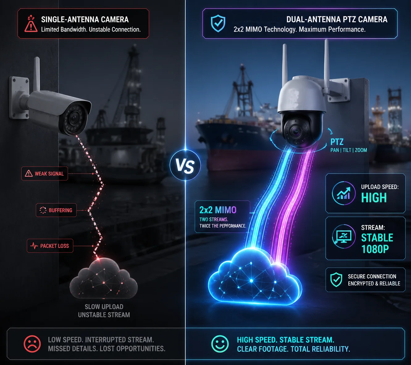
MIMO uses two antennas to send and receive multiple data streams at the same time. In a 2×2 MIMO setup, the 4G module can handle two parallel data flows. This can nearly double your upload speed compared to a single-antenna system, especially when signal quality is moderate.
 MIMO dual antenna upload speed 4G PTZ camera
How MIMO Actually Works in the Field
In LTE networks, the base station can split your data into two separate streams. Each stream travels through a different spatial path and arrives at a different antenna on your camera. The 4G module then reassembles the data. This is called Spatial Multiplexing. It works best when signal conditions are decent — typically when SINR 3 is above 10 dB.
But here is what most people do not realize. In weak signal areas, the network does not use spatial multiplexing. Instead, it switches to Transmit Diversity mode. In this mode, the base station sends the same data from multiple antennas. Your dual-antenna camera receives both copies and combines them. This does not double your speed, but it makes your connection much more reliable. It can mean the difference between a stable 1080p stream and constant buffering.
Real Numbers from Real Deployments
I have seen field tests where connecting a proper 2×2 MIMO antenna to a 4G terminal improved RSRP from -90 dBm to -66 dBm, and SINR jumped from nearly 0 to over 20. The link went from “barely connected” to “high quality” in seconds.
For a 4G solar PTZ camera running H.265+ encoding, I typically need about 1–3 Mbps upload for a stable 1080p stream. Here is how MIMO helps:
| Signal Condition | Single Antenna Upload | Dual Antenna (2×2 MIMO) Upload |
|---|---|---|
| Strong signal (RSRP > -80 dBm) | 8–15 Mbps | 15–30 Mbps |
| Moderate signal (-80 to -100 dBm) | 3–6 Mbps | 5–12 Mbps |
| Weak signal (-100 to -110 dBm) | 0.5–1.5 Mbps | 1.5–4 Mbps |
Why This Matters for 4K PTZ Streaming
At the weak signal end of the table, a single antenna barely pushes 1 Mbps. That is not enough for smooth video, even with H.265+ 4. But with dual-antenna MIMO, I am looking at 1.5 to 4 Mbps. That range is enough to run a crisp 1080p stream or even a compressed 4K stream in low-motion scenes like perimeter monitoring.
I always tell my clients: MIMO will not turn “no signal” into “full bars.” But in the zones where you have some signal — the edge areas, the in-between places — MIMO is what keeps your video feed alive. And when you combine it with H.265+ encoding that cuts bandwidth needs by 50% or more, you have a system that actually works in the real world.
Will the Dual-Antenna Setup Reduce “Signal Fading” in Areas with Heavy Interference?
I have deployed cameras near oil refineries, metal warehouses, and dense tree lines. Single-antenna cameras drop out constantly in these spots. The signal comes and goes like a flickering light.
Yes, dual-antenna setups significantly reduce signal fading caused by multipath interference. By using space diversity and cross-polarization, two antennas capture different versions of the same signal. The system picks the stronger one or combines both, which can recover 3 dB to 5 dB of lost signal strength.
 dual antenna reduce signal fading multipath interference
What Causes Signal Fading in the First Place?
Radio signals do not travel in a straight line and stop. They bounce off buildings, the ground, trees, metal structures, and even water. Each bounce creates a copy of the signal that arrives at your antenna at a slightly different time and angle. These copies can add up constructively (making the signal stronger) or destructively (canceling each other out).
When destructive interference happens, your signal drops suddenly. This is called multipath fading. It can happen in milliseconds. Your camera might show three bars one second and zero bars the next. This is the root cause of the intermittent disconnects that frustrate so many of my clients.
How Dual Antennas Fight Fading
The physics is simple. Two antennas placed at different positions will experience different fading patterns. When one antenna hits a signal null (a dead spot), the other antenna is almost certainly not in the same null. The system can then select the better signal or combine both.
There are three main techniques:
Selection Combining
The system continuously monitors both antennas and picks the one with the stronger signal at any given moment. This is the simplest approach and works well for basic diversity.
Maximum Ratio Combining (MRC)
The system weighs both signals based on their quality and adds them together. This gives the best possible output. Most modern 4G modules use MRC.
Cross-Polarization Diversity
In our dual-antenna PTZ cameras, I configure one antenna for vertical polarization and one for horizontal polarization. After bouncing off surfaces, the signal’s polarization direction changes unpredictably. By covering both polarization planes, I capture more of the total signal energy.
The Result in Practice
In environments with heavy multipath — urban canyons, industrial complexes, forested areas — dual-antenna diversity typically provides an equivalent gain of 3 dB to 5 dB over a single antenna. That might sound small. But in RF engineering, every 3 dB doubles your effective received power. This means a dual-antenna PTZ camera can be installed 15% to 25% farther from the base station than a single-antenna camera and still maintain the same connection quality.
For my clients deploying on Texas ranches or Canadian mining sites, this extra margin is not just a nice feature. It is the difference between a camera that works and a camera that sits there blinking “offline.”
What Is the Recommended Distance Between the Two Antennas for Maximum Efficiency?
I once had a client who mounted both antennas right next to each other on the same bracket. He called me the next day confused. “Han, I am not seeing any improvement over a single antenna.”
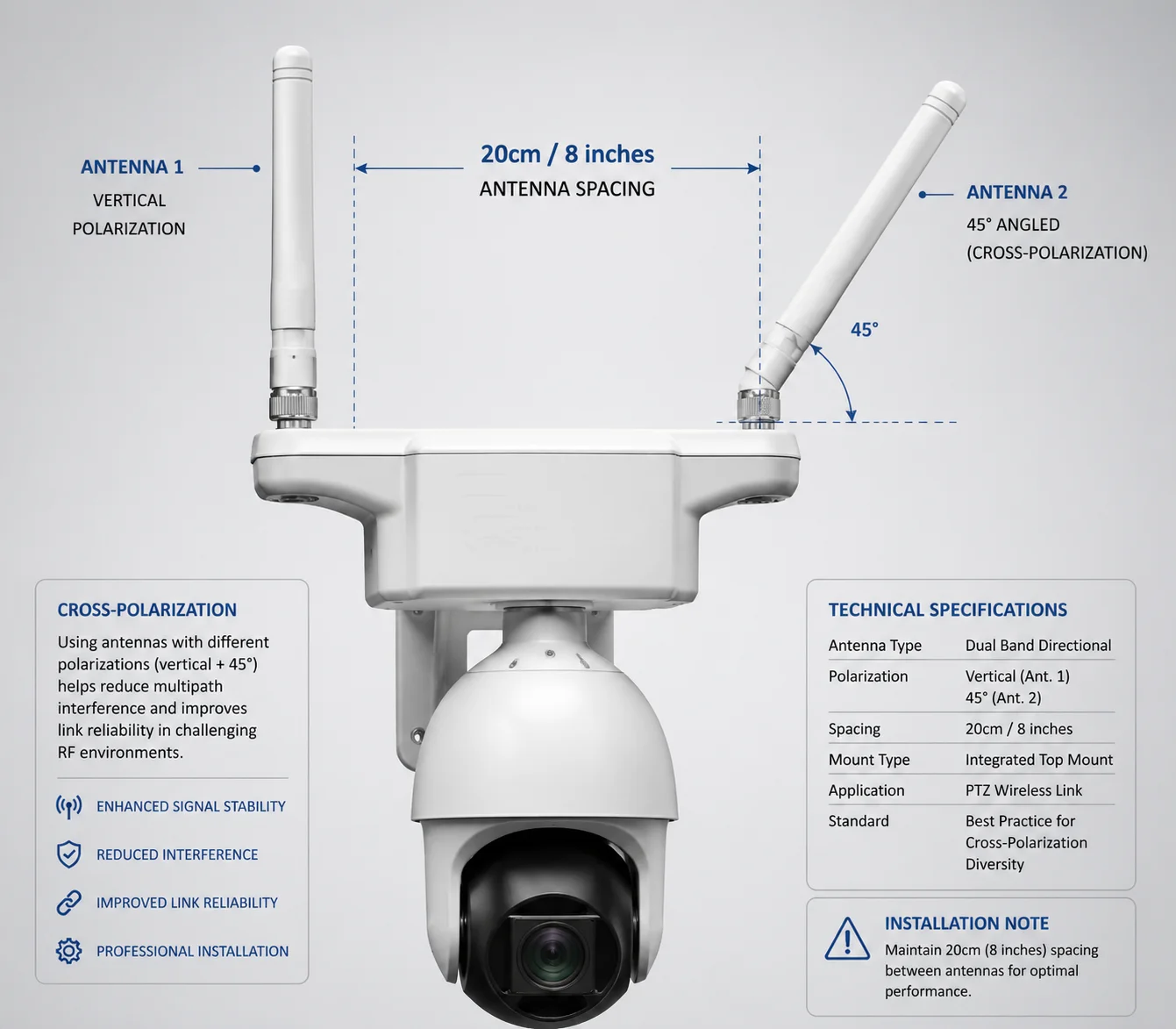
For maximum diversity gain, the two antennas should be spaced at least half a wavelength apart. For 4G LTE frequencies around 700 MHz, that means roughly 20 cm (8 inches). For 1800–2600 MHz bands, 6 to 8 cm (about 3 inches) is sufficient. Cross-polarization can reduce the required spacing further.
 antenna spacing distance dual antenna PTZ camera
Why Spacing Matters
The whole point of dual antennas is that they experience different signal conditions. If I put them too close together, they see almost the same signal — the same fades, the same nulls. The diversity benefit drops to nearly zero.
The general rule in antenna engineering is: minimum spacing of λ/4 to λ/2, where λ (lambda) is the wavelength of the operating frequency. At 4G LTE frequencies, the wavelengths vary a lot depending on the band.
Spacing Guidelines by Frequency Band
Here is a practical reference table I use when designing our camera antenna layouts:
| LTE Band | Frequency Range | Wavelength (λ) | Minimum Spacing (λ/4) | Recommended Spacing (λ/2) |
|---|---|---|---|---|
| Band 71 (600 MHz) | 617–698 MHz | ~46 cm | ~12 cm | ~23 cm |
| Band 12/13 (700 MHz) | 698–798 MHz | ~41 cm | ~10 cm | ~20 cm |
| Band 4 (1700 MHz) | 1710–1755 MHz | ~17 cm | ~4 cm | ~9 cm |
| Band 7 (2600 MHz) | 2500–2690 MHz | ~12 cm | ~3 cm | ~6 cm |
In our industrial PTZ cameras, the two antenna mounting points are pre-spaced based on the target LTE bands for each market. For US-bound units operating primarily on Band 12/13 and Band 71, I make sure there is at least 20 cm of separation between the two antenna bases.
Cross-Polarization as an Alternative
Sometimes physical space is limited. A PTZ camera housing is not infinitely large. In these cases, I use cross-polarized antennas instead of relying purely on spatial separation. One antenna is oriented vertically, the other at 45° or horizontally.
Cross-polarization achieves diversity through polarization difference rather than physical distance. This means I can mount the two antennas closer together — sometimes just 5 to 8 cm apart — and still get strong diversity performance. The key metric here is antenna isolation, which I want to see at 15 dB or better between the two ports.
Practical Tips for Field Installation
When my clients install external antennas on poles or masts, I give them three rules:
- Keep the antennas at least 20 cm apart if using the same polarization.
- Use cross-polarized antennas if space is tight.
- Do not wrap cables together. Keep the coaxial cables separated to avoid coupling and signal leakage between the two RF paths.
I have seen installations where the antennas were properly spaced, but the cables were zip-tied together for the entire 3-meter run. That killed the isolation and cut the diversity gain in half. Small details matter in RF work.
Conclusion
Dual-antenna design is not a luxury for remote PTZ deployments — it is a baseline requirement. Space diversity, MIMO, and proper antenna spacing keep your video feed stable where single-antenna cameras fail.
1. MIMO (Multiple-Input Multiple-Output) technology for LTE. ↩︎ 2. Yagi antenna design for directional long-range reception. ↩︎ 3. Signal-to-interference-plus-noise ratio for LTE quality. ↩︎ 4. H.265+ Smart Codec bandwidth reduction for 4G. ↩︎ 5. SMA vs TS9 antenna connector types for 4G modules. ↩︎ 6. Maximum Ratio Combining (MRC) for dual-antenna diversity. ↩︎ 7. RSRP (Reference Signal Received Power) measurement guide. ↩︎ 8. Multipath fading and space diversity in wireless systems. ↩︎ 9. Cross-polarization antenna configuration for PTZ cameras. ↩︎ 10. Antenna isolation measurement for dual-RF-path systems. ↩︎