
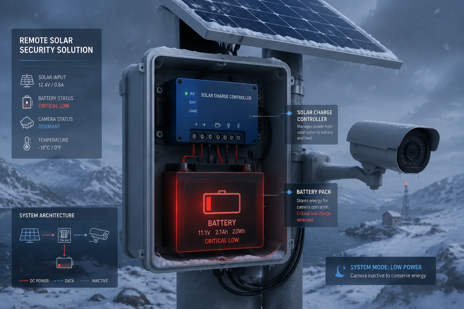
I lost a full battery in 12 days. The camera never turned on once. The controller alone drained it dry during a cloudy winter week.
A solar charge controller’s static power consumption — its self-consumption current in milliamps — directly determines how long your battery survives when sunlight is weak or absent. Controllers drawing 30–50mA can drain a small battery in under three weeks, while industrial-grade units consuming only 8–15mA extend standby life by 4–5 times under identical conditions.
 solar charge controller static power consumption low-light standby
Below, I break down exactly how this hidden spec impacts your off-grid surveillance system. I cover the math, the traps, and the design choices that separate reliable deployments from costly failures.
Table of Contents
Is the Quiescent Current Low Enough to Prevent Battery Drain During the Winter Solstice?
I deploy solar cameras in northern Canada. Winter solstice1 gives me barely 4 hours of weak sunlight. That is when quiescent current becomes a survival metric.
If your controller’s quiescent current exceeds the trickle charge your panel produces during short winter days, your battery loses net energy every single day. For winter solstice reliability, you need a controller with quiescent current below 15mA — ideally under 10mA — so the tiny solar harvest still results in positive net charge.
 quiescent current winter solstice battery drain solar controller
What Happens at the Winter Solstice
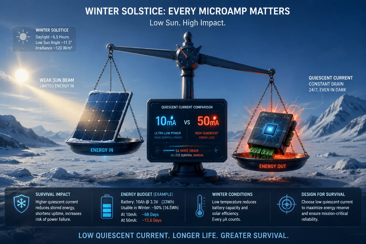
The winter solstice is the shortest day of the year. In places like Montana, Alberta, or northern Germany, you get 4–6 hours of usable daylight. But “usable” does not mean full power. Cloud cover, low sun angle, and snow reflection all reduce your panel output to a fraction of its rated capacity.
A 100W panel might produce only 10–20W during these hours. That translates to roughly 0.8A–1.6A at 12V for a very short window. The rest of the day — 18 to 20 hours — your system runs entirely on battery.
The Math That Matters
Let me show you a real scenario. Assume a 12V/50Ah lithium battery, a 100W panel in a northern location during winter solstice, and a 4G PTZ camera2 that draws 15W when active.
| Parameter | High Quiescent Controller (50mA) | Low Quiescent Controller (10mA) |
|---|---|---|
| Controller 24h drain | 1.2Ah | 0.24Ah |
| Camera active 2h/day | 2.5Ah | 2.5Ah |
| Total daily consumption | 3.7Ah | 2.74Ah |
| Winter solar harvest (est.) | 2.0Ah | 2.0Ah |
| Net daily loss | -1.7Ah | -0.74Ah |
| Days until battery empty | ~29 days | ~67 days |
That difference — 29 days versus 67 days — is the difference between a system that dies in January and one that survives until spring.
Why “Close Enough” Is Not Good Enough
Some engineers think 50mA is trivial. It sounds small. But in off-grid solar, every milliamp counts during the energy-scarce months. The problem compounds because:
- Battery capacity shrinks in cold weather. A 50Ah lithium battery at -10°C delivers roughly 40Ah. Your margin just got thinner.
- Snow covers panels. You might get zero harvest for 3–5 consecutive days.
- The controller never sleeps unless it has a dedicated low-power mode. It draws that current 24 hours a day, 365 days a year.
What I Recommend for Winter-Critical Sites
For any site above 45° latitude, I spec controllers with quiescent current under 12mA. The key hardware difference is the MCU architecture3. Our industrial-grade units achieve 8–15mA in normal operation and drop below 5mA in deep sleep mode4. This is not marketing — it is a measured value under no-load, no-charge conditions at 25°C.
Cheap controllers use general-purpose microcontrollers that were never designed for ultra-low-power operation. Industrial controllers use dedicated low-power MCUs paired with high-efficiency DC-DC converters that maintain regulation at microamp-level standby currents.
Does the Controller Have a “Low-Power Idle” State When No Solar Energy Is Present?
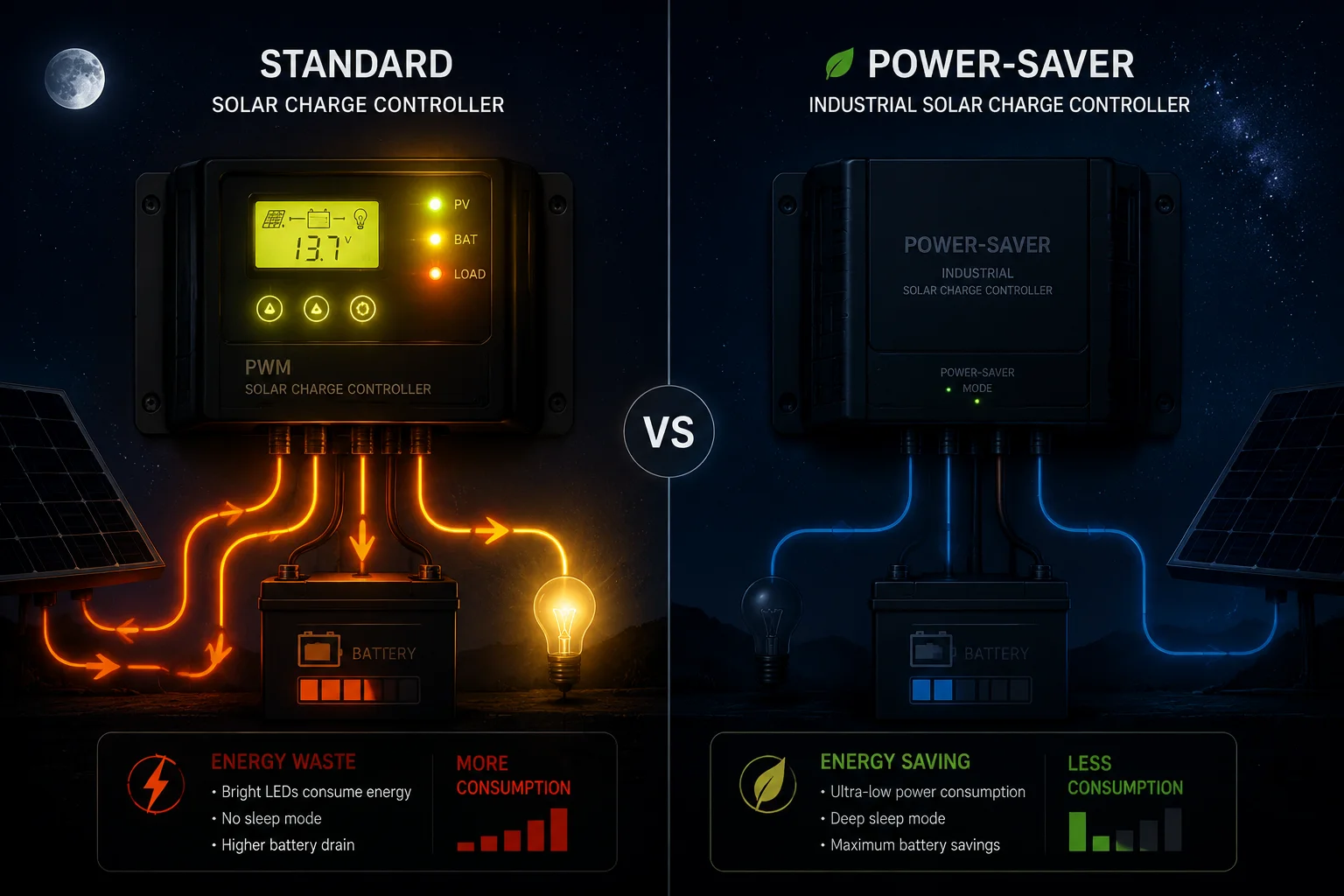
I once tested a controller that claimed “smart power management.” It drew 45mA around the clock, day and night, sun or no sun. That is not smart. That is lazy firmware.
A properly designed solar charge controller should automatically enter a low-power idle or deep sleep state when it detects no solar input and no active load. This state shuts down non-essential circuits — LEDs, display backlights, communication polling — and reduces current draw to 3–8mA, extending battery life by 3–5 times during prolonged darkness.
 low-power idle state solar charge controller night mode
What “Low-Power Idle” Actually Means in Hardware
A controller is not just a switch between your panel and battery. It contains a microprocessor, voltage regulators, MOSFETs, LED indicators, and often a communication interface (RS485, Bluetooth, or Wi-Fi). Each of these components draws current even when doing nothing useful.
A true low-power idle state means the firmware actively shuts down or duty-cycles these subsystems:
- LED indicators: Turned off completely or blinked once every 10 seconds instead of continuously.
- LCD/OLED display: Backlight off, refresh halted.
- Communication module: Polling interval extended from 1 second to 60 seconds, or module powered down entirely.
- ADC sampling: Voltage and current measurements reduced from 10Hz to once per minute.
- MOSFET gate drivers: Held in a static state, no PWM switching.
The Difference Between “Sleep” and “Off”
This is important. A controller in low-power idle is not off. It still monitors battery voltage. It still watches for sunrise (solar input returning). It still responds to wake-up triggers. The difference is that it does these things at minimum energy cost.
Think of it like a security guard who sits quietly in the dark versus one who keeps all the lights on and walks laps every 5 minutes. Both are “on duty.” One costs far less energy.
How Cheap Controllers Fail Here
Most budget controllers under $15 have no idle state at all. Their firmware runs a single loop:
- Check solar voltage.
- Check battery voltage.
- Update LED status.
- Repeat immediately.
This loop runs thousands of times per second, keeping the CPU at full clock speed 24/7. There is no reason for this at night. But implementing proper sleep modes requires more sophisticated firmware — interrupt-driven wake-up, clock scaling, peripheral power gating. That costs engineering time, which budget manufacturers skip.
What Our Industrial Controllers Do Differently
At , our controllers use a tiered power management approach:
| State | Trigger | Current Draw | Active Functions |
|---|---|---|---|
| Full Active | Solar input > 1V, load on | 15–25mA | All systems running, MPPT5 active. |
| Charge Idle | Solar input > 1V, load off | 10–15mA | MPPT active, comms reduced |
| Night Watch | Solar input = 0V, load off | 5–8mA | Battery monitoring, wake timer |
| Deep Sleep | Solar = 0V, battery < 30% | 2–4mA | Voltage watchdog only |
The transition between states is automatic. No user configuration needed. The controller detects conditions and responds. When the sun rises and panel voltage climbs above the threshold, the controller wakes up within 200 milliseconds and resumes normal charging.
This is the kind of firmware intelligence that separates a $12 controller from a $35 industrial unit. The hardware cost difference is maybe $3. The engineering investment in firmware is where the real value lives.
How Much of My 100Ah Battery Is Consumed by the Controller Itself Over a Month?
I had a client call me, frustrated. His 100Ah battery was at 60% after one month. His camera was scheduled to run only 4 hours per day. Where did the other 30% go? The answer was his controller.
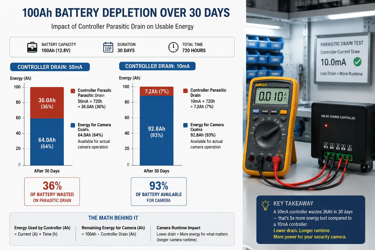
A controller drawing 50mA consumes 36Ah from a 100Ah battery over 30 days — that is 36% of your total capacity gone before your camera takes a single photo. A low-power controller at 10mA uses only 7.2Ah over the same period, preserving 93% of battery capacity for your actual surveillance equipment.
 100Ah battery consumption solar controller self-drain monthly
The Simple Math
This calculation is straightforward. No complex formulas needed.
Monthly controller consumption = Current (A) × 24 hours × 30 days
- 50mA controller: 0.050A × 24 × 30 = 36Ah per month
- 30mA controller: 0.030A × 24 × 30 = 21.6Ah per month
- 15mA controller: 0.015A × 24 × 30 = 10.8Ah per month
- 10mA controller: 0.010A × 24 × 30 = 7.2Ah per month
- 5mA controller: 0.005A × 24 × 30 = 3.6Ah per month
Now put this in context. A 100Ah battery should never be discharged below 20% (for lithium) or 50% (for lead-acid). So your usable capacity is 80Ah or 50Ah respectively (for lithium vs. lead-acid)6.
The Real-World Impact
A 50mA controller on a 100Ah lithium battery eats 36Ah out of your 80Ah usable capacity. That is 45% of your usable energy — gone. Not to your camera. Not to your 4G modem. Just to keep the controller’s circuits alive.
This is why David’s clients sometimes report “the battery dies too fast.” They sized the battery for the camera load. They forgot the controller is a 24/7 parasite.
How to Audit Your Own System
Here is what I tell every integrator:
- Disconnect the load. Remove the camera and modem from the controller output.
- Cover the solar panel. Block all light so no charging occurs.
- Measure current. Put a multimeter in series with the battery positive wire going into the controller.
- Wait 5 minutes. Let the controller settle into its idle state.
- Read the number. That is your true static consumption.
If the datasheet says 10mA and your meter reads 45mA, you have a problem. I have seen this happen with controllers that leave Bluetooth or Wi-Fi modules powered on by default, even when no phone is connected.
Sizing Your Battery Correctly
When I design a system for a client, I always add the controller’s monthly consumption to the load budget. Here is my formula:
Required battery capacity = (Daily camera load + Daily controller drain) × Autonomy days ÷ Depth of discharge
For a 4G PTZ camera drawing 1.5A for 6 hours per day, with a 10mA controller, and 5 days of autonomy on lithium:
- Daily camera load: 1.5A × 6h = 9Ah
- Daily controller drain: 0.01A × 24h = 0.24Ah
- Total daily: 9.24Ah
- 5-day reserve: 46.2Ah
- Divided by 0.8 DoD: 57.75Ah minimum
With a 50mA controller, that same calculation yields 63.5Ah minimum. The difference grows with longer autonomy requirements. For 10-day autonomy, you are looking at 115Ah versus 96Ah. That is a bigger, heavier, more expensive battery — all because of a bad controller choice.
Why Do Some Cheap Controllers Waste Up to 20% of the Battery Just Staying “Awake”?
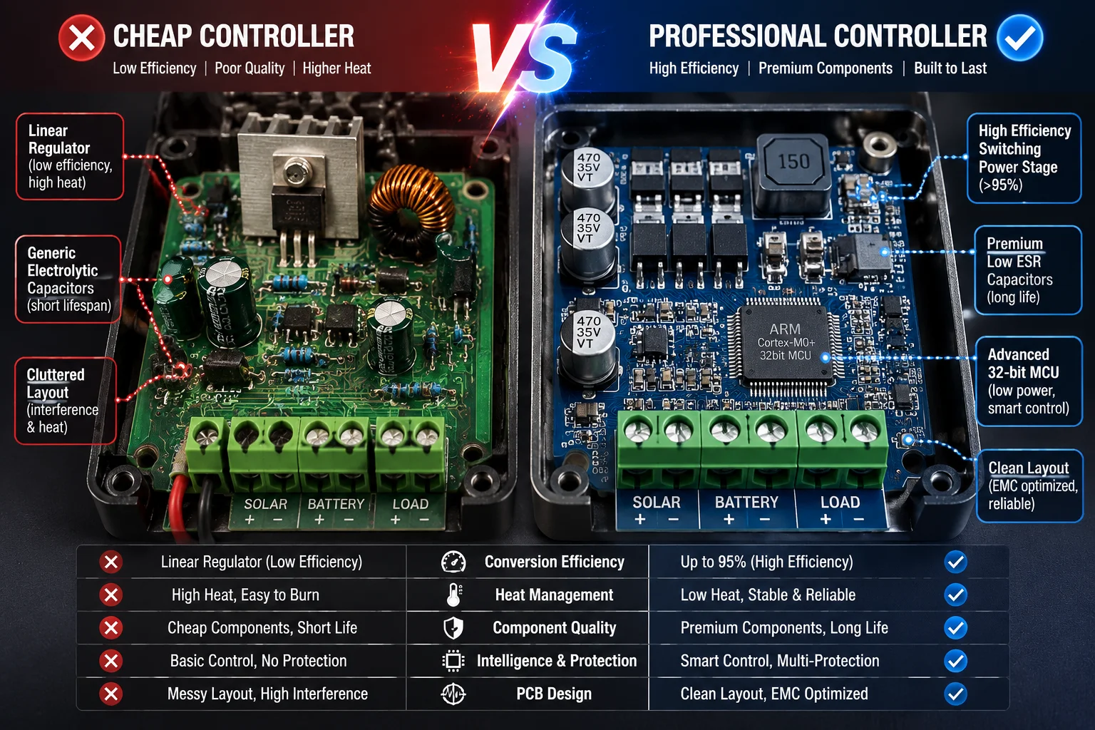
I tore apart a $9 solar controller from a popular marketplace. Inside, I found a full-speed ARM processor running at 72MHz with no sleep mode enabled. It was like leaving a car engine running in a parking lot 24 hours a day.
Cheap controllers waste excessive battery power because they use general-purpose components not designed for low-power operation, run firmware without sleep states, keep unnecessary peripherals active around the clock, and use inefficient linear voltage regulators instead of high-efficiency switching converters. These design shortcuts save the manufacturer $2–3 per unit but cost the end user hundreds in wasted energy and premature battery replacement.
 cheap solar controller high power waste teardown comparison
The Four Root Causes of Wasted Power
I have opened dozens of controllers on my workbench. The pattern is always the same. Cheap controllers waste power for four specific, identifiable reasons.
1. Wrong MCU Choice
Budget controllers use whatever microcontroller the factory already has in stock. Often this is a general-purpose chip designed for consumer electronics — devices that are always plugged into wall power. These chips have clock speeds of 48–72MHz and no meaningful low-power modes.
An industrial solar controller uses a dedicated ultra-low-power MCU. These chips can run at 1–4MHz for basic monitoring tasks and drop into sleep modes that draw single-digit microamps. The price difference between these chips is $0.30–$0.80. But the factory needs firmware engineers who understand power management. That is the real cost they skip.
2. Linear Regulators Instead of Switching Converters
The controller needs to step down the 12V battery voltage to 3.3V for its logic circuits. There are two ways to do this:
- Linear regulator7 (LDO): Simple, cheap ($0.05). But it wastes the voltage difference as heat. Efficiency at 12V-to-3.3V conversion: about 27%. If the logic needs 10mA at 3.3V, the regulator draws 36mA from the 12V battery.
- Switching converter8 (buck): Slightly more complex ($0.40). Efficiency: 85–95%. The same 10mA logic load draws only 3–4mA from the 12V battery.
This single component choice can account for a 30mA difference in static consumption.
3. Always-On Peripherals
Cheap controllers keep everything powered all the time:
- Status LEDs glowing continuously (5–20mA each)
- Bluetooth module scanning for connections (15–30mA)
- LCD backlight on permanently (20–40mA)
- USB interface powered even with nothing connected (5–10mA)
A well-designed controller powers these peripherals only when needed. LEDs blink briefly every few seconds. Bluetooth activates only when a button is pressed. The display turns off after 30 seconds of inactivity.
4. No Firmware Power Management
Even with good hardware, bad firmware wastes power. I have seen controllers with capable low-power MCUs that never enter sleep mode because the programmer did not implement it. The main loop runs continuously, polling sensors that have not changed, refreshing displays nobody is looking at, and checking communication buffers that are empty.
The Cost to You as an Integrator
| Cost Factor | Cheap Controller (50mA) | Industrial Controller (10mA) |
|---|---|---|
| Controller price | $9 | $35 |
| Monthly battery waste | 36Ah | 7.2Ah |
| Annual battery degradation | Faster (deeper cycles) | Slower (shallow cycles) |
| Battery replacement interval | 2–3 years | 4–6 years |
| Truck roll risk | High (system dies in winter) | Low (survives extended cloudy periods) |
| Total 5-year cost | $9 + $200 battery × 2 = $409 | $35 + $200 battery × 1 = $235 |
The cheap controller costs more in the long run. Every time a battery dies prematurely, someone has to drive to a remote site, swap the battery, and reconfigure the system. For David’s clients deploying cameras on construction sites or rural farms, that truck roll costs $150–$500 depending on distance.
What to Look for on a Datasheet
When you evaluate a controller, look for these specific claims:
- “Self-consumption” or “quiescent current” listed in milliamps. If it is not on the datasheet, assume the worst.
- “Sleep mode” or “low-power idle” mentioned in the features. Ask for the sleep-mode current specifically.
- Switching regulator mentioned in the power supply section. If it says “linear regulator” or does not specify, it is probably wasting power.
- MCU model number. If you can identify it, look up its sleep-mode current. Chips from the STM32L series, MSP430, or similar low-power families are good signs.
At , we publish both active and sleep-mode current specifications for every controller we ship. We also provide oscilloscope captures showing the transition between power states. This is the level of transparency that professional integrators like David require — and deserve.
Conclusion
Static power consumption is the silent killer of off-grid solar systems. Choose a controller with sub-15mA quiescent current and verified sleep modes. Your battery, your budget, and your reputation will thank you.
1. Understand the astronomical basis for minimal daylight in high latitudes. ↩︎ 2. Understand PTZ camera technology and its power requirements in surveillance. ↩︎ 3. Overview of low-power MCU architectures suitable for battery devices. ↩︎ 4. Explore how microcontrollers achieve deep sleep modes to minimize power consumption. ↩︎ 5. Learn about Maximum Power Point Tracking technology used in solar charge controllers. ↩︎ 6. Comparison with lead-acid chemistry, including discharge limits. ↩︎ 7. Understand why linear regulators waste power in battery-powered applications. ↩︎ 8. Learn how switching converters achieve higher efficiency than linear regulators. ↩︎