
I have seen batteries die silently in the field. No warning. No alarm. Just a slow, invisible drain that kills the cell chemistry forever.
A well-designed BMS controls static leakage current1 by entering a deep sleep mode that draws less than 50μA, shutting down balancing circuits when idle, and using multi-stage voltage cut-offs to protect the last reserves of battery energy before permanent damage occurs.
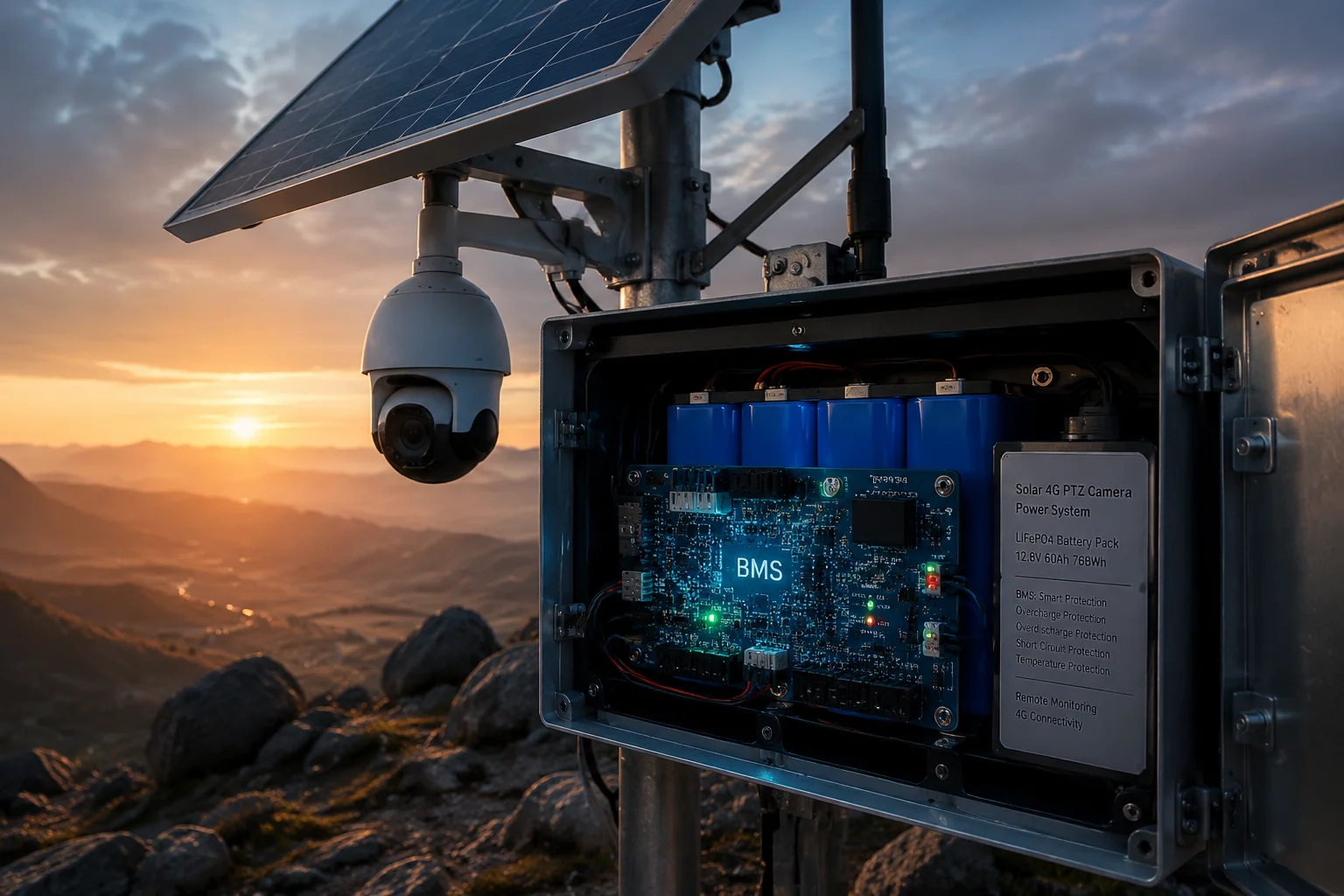 BMS static leakage current control solar surveillance
Below, I break down exactly how this works at the hardware level, and what numbers you should demand from your supplier before you commit to a battery pack for your off-grid 4G solar surveillance project.
Table of Contents
What Is the “Micro-Amp” Draw of the System When It Is in Its Deepest Sleep Mode?
I used to think “sleep mode” meant low power. Then I measured a cheap BMS pulling 8mA around the clock. That tiny number killed a 20Ah battery in under three months.
In the deepest sleep state, a quality BMS reduces its own current draw to between 20μA and 50μA by shutting down all peripheral circuits and keeping only a single hardware comparator alive for wake-up detection.
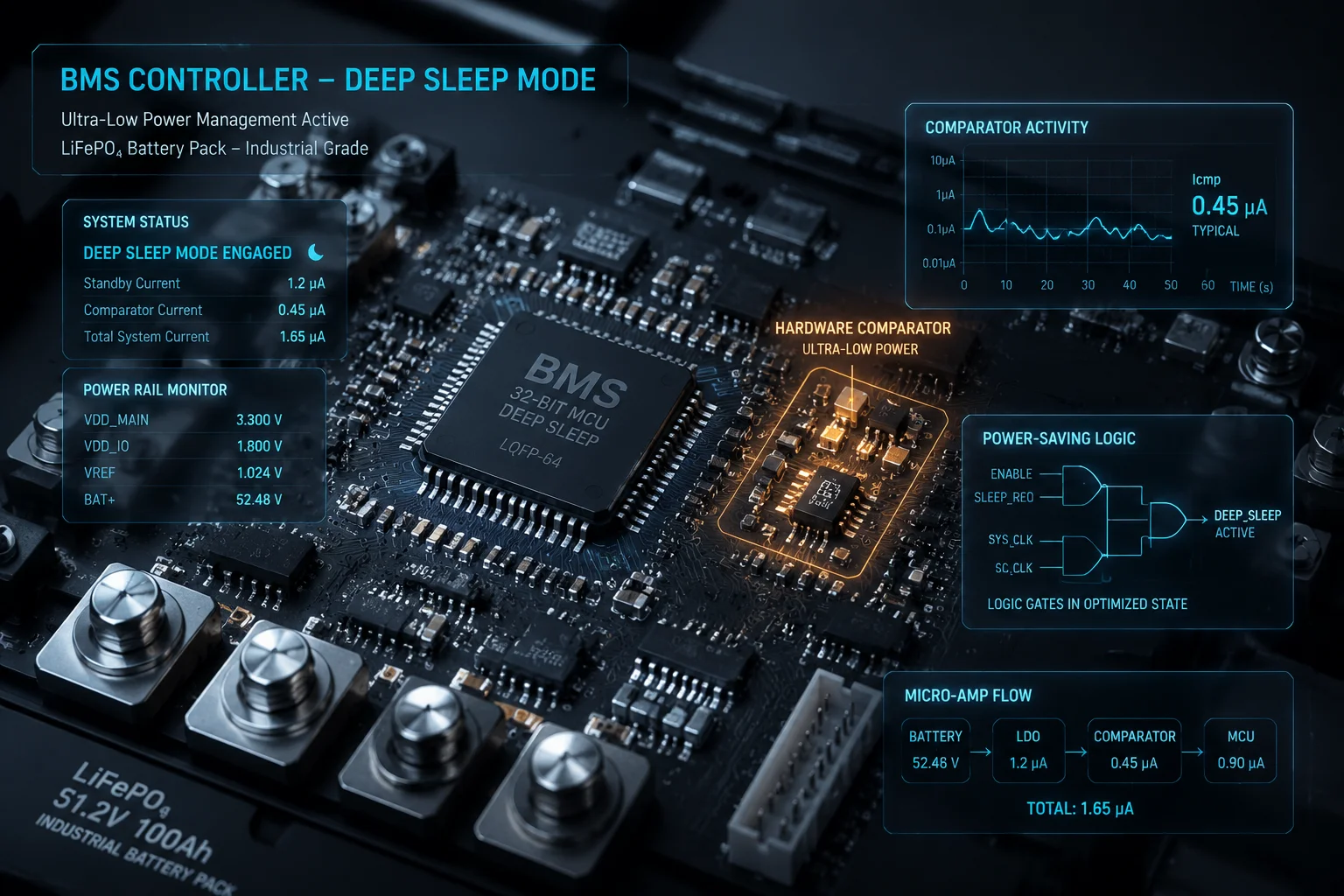 BMS deep sleep mode micro-amp current draw
How Deep Sleep Actually Works at the Chip Level
The BMS main controller (MCU) does not run at full speed all the time. It uses a layered power architecture. When the system detects no charge current and no load current for a set period, the MCU turns off its ADC, communication bus, LED drivers, and balancing FETs. What remains active is a tiny comparator circuit that watches for two things: a rising voltage on the charge input (the sun came up), or a load pulse on the output (the camera woke up). When either signal crosses a threshold, the comparator fires a hardware interrupt. The MCU wakes up in milliseconds and resumes full operation.
Why Micro-Amps Matter for Off-Grid Math
Let me put this in real numbers. A bad BMS with 8mA static draw will consume:
8mA × 24h × 30 days = 5.76Ah per month
For a 20Ah LiFePO4 battery, that is nearly 29% of total capacity gone before the camera even turns on. Now compare that to a proper BMS at 30μA:
0.03mA × 24h × 30 days = 0.0216Ah per month
That is essentially zero. The difference between these two numbers is the difference between a system that survives winter and one that dies.
Key Parameters to Request from Your Supplier
| Parameter | Bad BMS | Acceptable BMS | Industrial Grade BMS |
|---|---|---|---|
| Sleep current | 5–10 mA | 100–500 μA | 20–50 μA |
| Wake-up time | 500 ms+ | 50 ms | < 5 ms |
| Wake-up trigger | Software timer only | Voltage threshold | Hardware comparator interrupt |
| Monthly drain (30 days) | 3.6–7.2 Ah | 0.07–0.36 Ah | 0.014–0.036 Ah |
When you ask a factory for their BMS datasheet, look for the line that says “Self-consumption in sleep mode” or “Quiescent current.” If that number is missing from the spec sheet, walk away. A manufacturer who does not test and publish this number has not designed for off-grid use.
Will My Battery Survive a 30-Day “No-Sun” Period Without Hitting the Critical Low-Voltage?
I have fielded calls from integrators in the Pacific Northwest who lost entire deployments during a cloudy November. Their batteries hit under-voltage lockout2 on day 18. The cameras never came back online without a truck roll.
Whether your battery survives 30 days without sun depends on three factors: the BMS sleep current, the total battery capacity, and how aggressively the system sheds loads at each voltage threshold. A properly configured system with a 50Ah LiFePO4 pack and sub-100μA BMS sleep current can idle for 90+ days without reaching critical voltage.
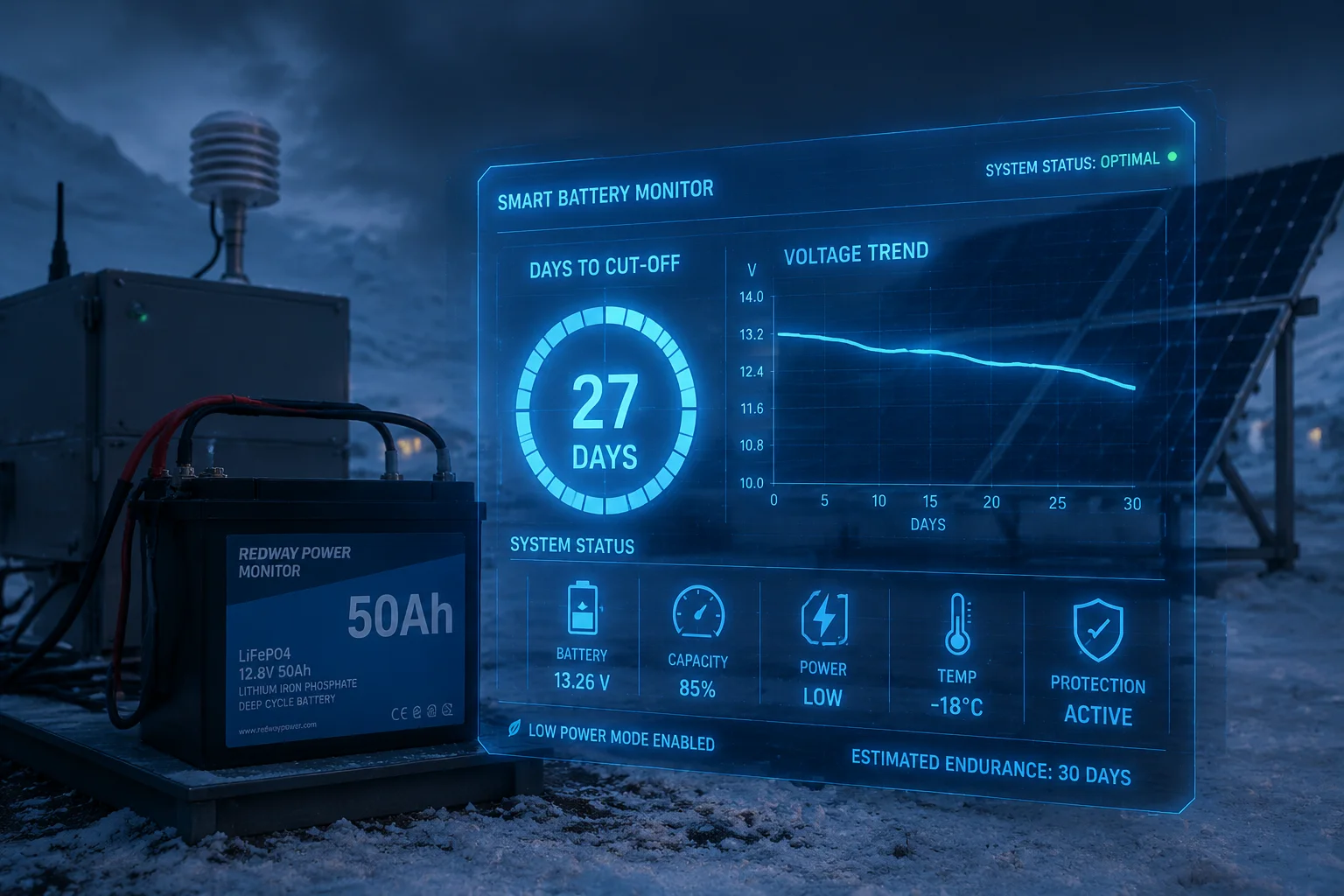 battery survival 30 day no sun period off-grid
The Survival Equation
The math is straightforward. You need to know three numbers:
- Total usable battery capacity (Ah)
- Total system idle draw (mA) — this includes BMS, modem standby leakage, and any always-on sensors
- The voltage floor where the BMS cuts everything off
Survival time (hours) = Usable capacity (mAh) ÷ Total idle draw (mA)
For a 50Ah (50,000mAh) pack with a total system idle draw of 0.5mA (BMS at 50μA + modem hard-off + camera hard-off + misc leakage at 450μA):
50,000 ÷ 0.5 = 100,000 hours = 4,166 days
That is over 11 years on paper. But reality is messier. You lose capacity to temperature effects, cell aging, and the fact that you cannot use 100% of the rated capacity without damaging the cells. A safe usable window for LiFePO4 is about 80% of rated capacity. So the real number is closer to 3,300 days. Still far beyond 30 days.
Where Systems Actually Fail
The problem is almost never the BMS alone. It is the other components that refuse to fully shut down. A 4G modem in “off” mode might still pull 1–3mA through its voltage regulator. A camera’s IR-cut filter driver might leak 0.5mA. These parasitic paths add up fast.
Worst-Case Scenario Planning
| System Configuration | Total Idle Draw | Days to Hit 10.5V (50Ah LiFePO4) |
|---|---|---|
| Bad BMS + modem standby leak | 12 mA | 138 days |
| Good BMS + modem hard-cut | 0.5 mA | 3,300+ days |
| Good BMS + modem soft-off (leaking) | 3.5 mA | 476 days |
| No BMS sleep mode at all | 25 mA | 66 days |
The takeaway: even in the worst realistic case with a good BMS and a properly isolated modem, 30 days is not a problem. The danger comes when designers assume “off” means zero current. It never does, unless you physically disconnect the path with a MOSFET switch controlled by the BMS.
Temperature Derating
In cold climates, LiFePO4 cells lose about 10–20% of their effective capacity at 0°C and up to 40% at -20°C. If your deployment site sees freezing temperatures during the no-sun period, you must factor this into your survival calculation. A 50Ah pack at -10°C behaves more like a 35Ah pack.
Does the BMS Shut Down Its Own Circuitry to Save the Last 5% of Battery Energy?
I learned this lesson the hard way. A BMS that stays awake to “protect” the battery can actually be the thing that kills it. The protector becomes the parasite.
Yes. A properly designed BMS implements a multi-stage shutdown sequence. At the final stage, it enters “shipping mode” where it cuts power to its own logic circuits, reducing draw to nano-amp levels, specifically to preserve the last remaining energy and prevent irreversible cell damage.
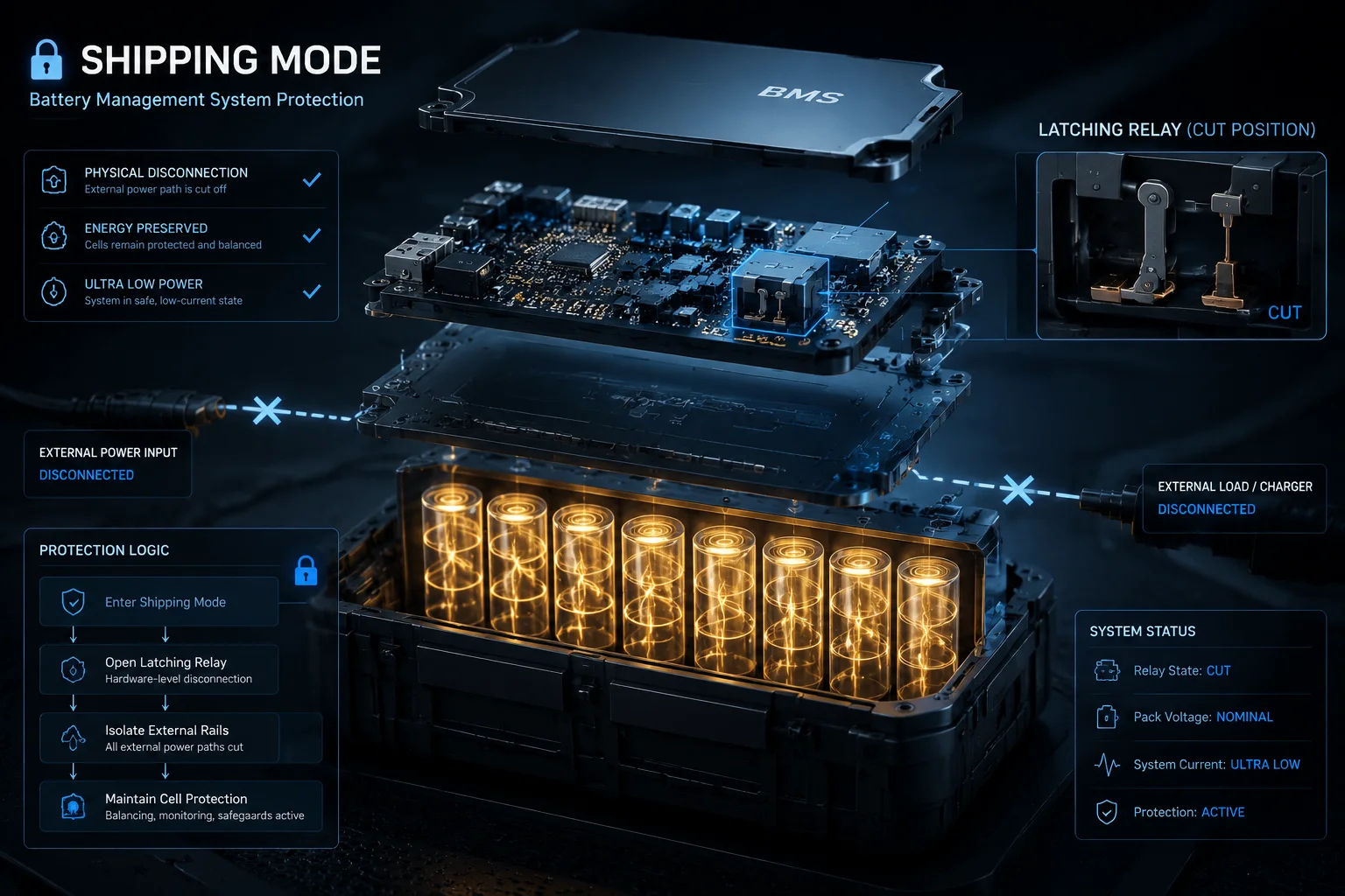 BMS shipping mode self shutdown circuitry
The Three-Stage Protection Sequence
Industrial BMS units do not just have one cut-off point. They use a tiered approach that progressively sheds load and finally shuts down themselves. Here is how a well-designed system handles a dying battery:
Stage 1 — Warning (11.8V for a 4S LiFePO4 pack): The BMS sends a low-battery flag to the system controller. If the system has connectivity, it pushes an alert to the user’s app or monitoring dashboard. The system may reduce its wake-up frequency from every 15 minutes to every 2 hours.
Stage 2 — Load Disconnect (11.2V): The BMS opens the discharge MOSFET and cuts power to all external loads. The camera, modem, and router all lose power. Only the BMS itself remains active, monitoring cell voltages and waiting for a charge source.
Stage 3 — Self Shutdown / Shipping Mode (10.5V): The BMS recognizes that if it stays awake, its own consumption will drag the cells below the absolute minimum safe voltage (typically 2.0V per cell for LiFePO4). At this point, it enters shipping mode3; the MCU commands a latch circuit to cut its own power rail. The only current flowing is the reverse leakage of the MOSFET body diodes4 and the latch circuit itself — typically in the range of 50–500 nanoamps.
Why This Matters for Cell Chemistry
LiFePO4 cells can tolerate being stored at low state-of-charge much better than lithium-ion NMC cells. But even LiFePO4 has a hard floor. If a cell sits below 2.0V for extended periods, the copper current collector on the anode begins to dissolve into the electrolyte. This creates internal short circuits that are permanent. The cell is dead. No amount of charging will bring it back.
The BMS shipping mode exists specifically to prevent this. By cutting its own power at 10.5V (2.625V per cell in a 4S configuration), it leaves a comfortable margin above the 2.0V death line. This margin accounts for continued self-discharge5 of the cells themselves (which is separate from BMS draw) over many months of storage.
How to Verify This Feature
Ask your supplier: “What is the current draw in shipping mode, and how is the system re-activated?” A good answer sounds like: “Less than 1μA in shipping mode. Re-activation requires connection to a charger — the BMS detects charge voltage through a dedicated sense pin and latches itself back on.” A bad answer sounds like: “It goes to sleep.” Sleep and shipping mode are not the same thing.
How Do You Prevent “Parasitic Drain” from the 4G Modem When the System Is Off?
I have measured 4G modules that claim to be “off” but still pull 2.5mA through their internal voltage regulators. Over a month, that is 1.8Ah gone. For a small battery, that is the difference between life and death.
You prevent parasitic drain from the 4G modem by placing a P-channel MOSFET on the modem’s power rail, controlled directly by the BMS. When the system enters sleep, the BMS drives the MOSFET gate high, physically disconnecting the modem from the battery. No software “off” command is trusted — only a hard electrical cut guarantees zero current flow.
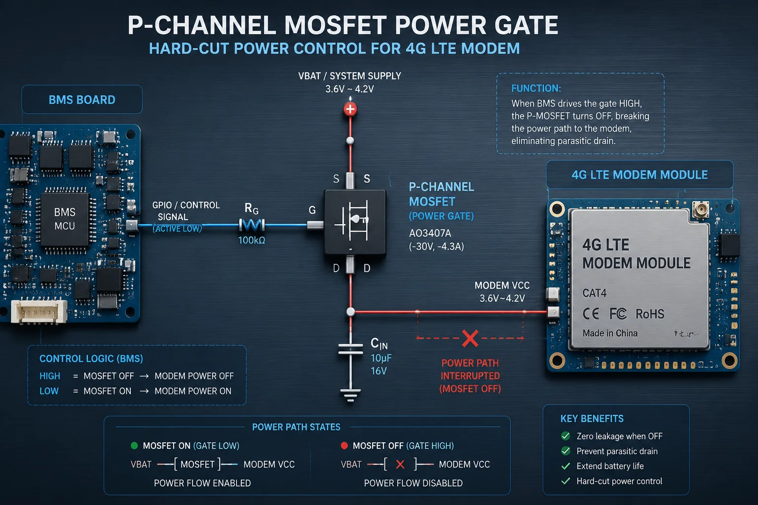 parasitic drain 4G modem MOSFET power cut
Why Software “Off” Is Never Enough
A 4G modem module like the Quectel EC256 or SIMCom A76707 has internal circuitry that remains partially powered even when you send an AT+QPOWD command. The module’s power management IC (PMIC) keeps its RTC (real-time clock) alive. The SIM card interface maintains a small bias current. The RF front-end has ESD protection diodes that create leakage paths.
These are not design flaws. They are intentional features for fast wake-up in consumer devices. But in an off-grid solar system, they become parasitic drains that the BMS must eliminate.
The Hardware Solution: High-Side MOSFET Switch
The correct approach is a high-side P-channel MOSFET between the battery rail and the modem’s VCC input. The BMS GPIO pin controls this switch through a level shifter8 or gate driver. When the BMS decides the modem should be off, it pulls the MOSFET gate to the source voltage, turning it fully off. The modem sees zero volts. No leakage path exists because the MOSFET’s off-state leakage is in the nanoamp range.
Common Parasitic Drain Sources and Solutions
| Component | Typical “Off” Leakage | Root Cause | Solution |
|---|---|---|---|
| 4G modem (software off) | 1–3 mA | Internal PMIC, RTC, SIM bias | High-side MOSFET hard cut |
| PTZ camera (standby) | 5–15 mA | IR-cut filter driver, video encoder idle | Dedicated power MOSFET per channel |
| Voltage regulator (no load) | 0.5–2 mA | Regulator quiescent current | Use ultra-low Iq regulators (< 1μA) or cut input power |
| Status LEDs | 1–5 mA | Always-on indicator | Remove or gate with sleep signal |
| Pull-up resistors on I2C/SPI | 0.1–0.5 mA | Bus lines held high into unpowered ICs | Switchable pull-ups or bus isolators |
Design Rule for Off-Grid Systems
Every power rail that feeds a non-essential peripheral must have its own MOSFET switch controlled by the BMS. This is not optional. It is the only way to guarantee that “off” means truly zero current. In our solar PTZ systems, we implement individual power domains for the camera module, the 4G modem, the WiFi radio, and the heater circuit. Each domain can be independently enabled or disabled by the BMS based on battery state, time of day, or user-configured schedules.
The BMS becomes the master power controller for the entire system — not just a battery monitor, but an intelligent power router that decides which subsystems deserve energy and which ones get cut off to preserve the battery.
Conclusion
Static leakage current is the silent killer of off-grid batteries. A quality BMS fights it with nano-amp sleep modes, hard MOSFET power cuts, and multi-stage self-shutdown. Always demand the “sleep current” spec before you buy.
1. Understand the phenomenon of unwanted current flow that drains batteries when devices are supposed to be off. ↩︎ 2. Learn how UVLO prevents battery damage by disabling loads at critical low voltage. ↩︎ 3. Read Texas Instruments’ application note on BMS shipping mode for nano-amp battery preservation. ↩︎ 4. Understand the tiny currents that can still flow even when MOSFETs are turned off. ↩︎ 5. Learn about the internal chemical reaction that drains battery capacity over time. ↩︎ 6. View the specs of the Quectel EC25 4G LTE module commonly used in IoT surveillance. ↩︎ 7. Explore the SIMCom A7670 4G module and its power management features. ↩︎ 8. Find out how level shifters interface BMS GPIOs with MOSFET gates at different voltages. ↩︎