
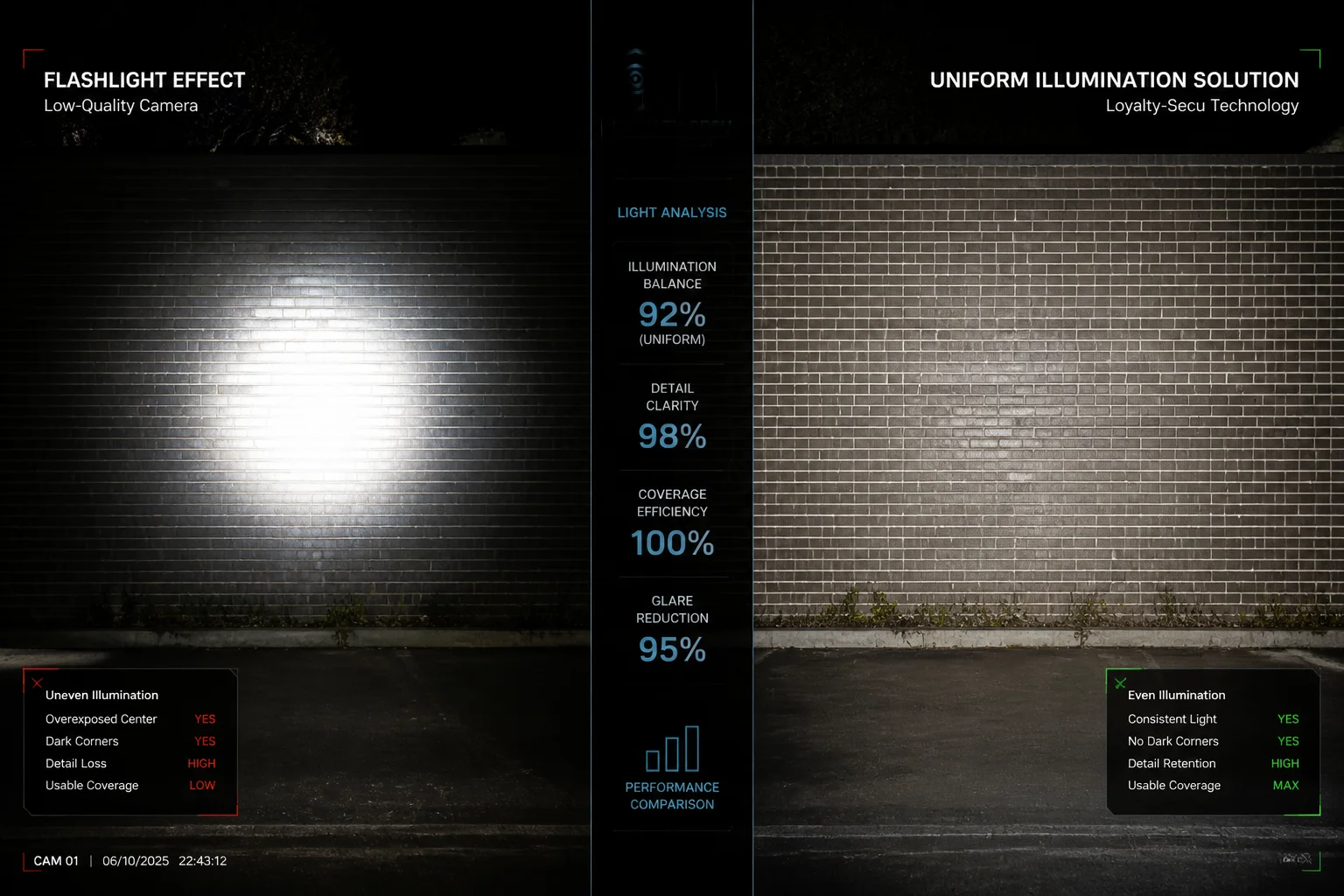
I have seen too many laser PTZ cameras that look great on paper but deliver a “flashlight” image at night — a white blob in the center and pure black around the edges.
The fix requires three layers working together: optical beam shaping to flatten the laser spot, synchronized zoom-laser control to match the beam angle to the lens FOV at every focal length, and ISP-level algorithms like HLC and BLC to fine-tune the final image. No single adjustment alone can fully solve this problem.
 laser PTZ camera uniform illumination solution
Below, I will break down each common laser lighting issue, explain why it happens, and show you exactly what to ask your supplier — or what to adjust on site — so your next project delivers clean, even night images from edge to edge. Let’s get into it.
Table of Contents
Does Your Laser PTZ Use a “Homogenization” Lens to Ensure Uniform Light Distribution?
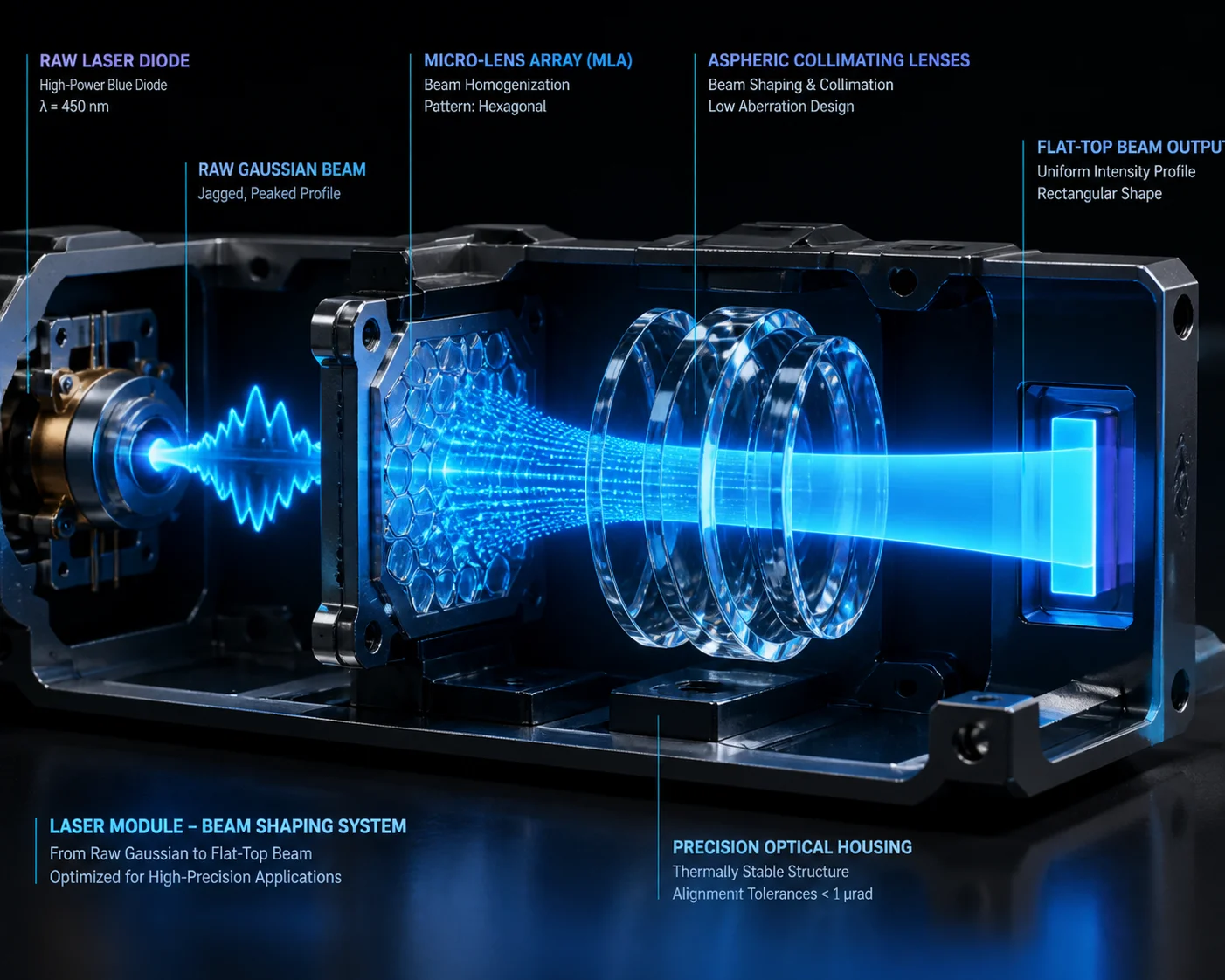
Most cheap laser cameras skip the beam-shaping optics entirely. The result is a raw Gaussian hot spot that burns out the center and leaves the corners in total darkness.
Yes, our laser PTZ modules use aspheric lens groups or micro-lens arrays (MLA) 1 in front of the laser diode to reshape the natural Gaussian beam into a flat-top profile. This spreads laser energy evenly across the full field of view, removing the central hot spot and filling in dark edges.
 laser beam homogenization flat-top vs Gaussian
Why Raw Laser Beams Create Uneven Light
A laser diode outputs light in a Gaussian distribution 2. Think of it like a flashlight with no reflector — the center is extremely bright, and brightness drops off fast as you move outward. When a camera sensor sees this, the center pixels clip to pure white while the edge pixels stay near black. No amount of software tuning can recover detail that was never illuminated in the first place.
What “Homogenization” Actually Means in Optics
Beam homogenization is the process of converting that peaked Gaussian profile into a flat-top (also called “top-hat”) profile. There are several ways to do this, including Diffractive Optical Element (DOE) 5 technology for precision beam shaping.
| Method | How It Works | Cost Level |
|---|---|---|
| Aspheric Lens Group | Multiple curved lenses redistribute energy from center to edges | Medium |
| Micro-Lens Array (MLA) | A grid of tiny lenses breaks and recombines the beam into a uniform pattern | Medium-High |
| Diffractive Optical Element (DOE) | A precision-etched surface uses diffraction to shape the beam | High |
| Simple Diffuser | A frosted or engineered diffuser scatters light broadly | Low |
A simple diffuser is cheap but wastes a lot of laser power. It also creates a soft, undefined edge. An MLA or DOE keeps more energy on target and gives a sharp, well-defined illumination boundary. For serious long-range PTZ work — 500 meters and beyond — you want MLA or aspheric designs, not a basic diffuser.
What to Ask Your Supplier
When you evaluate a laser PTZ, do not just ask “does it have uniform light?” That question is too vague. Instead, put these into your technical specification:
- “Laser illumination shall use beam-shaping optics (diffuser, MLA, or DOE) to produce a flat-top beam profile.”
- “Supplier shall provide a beam uniformity test report showing center-to-edge illuminance ratio at 300m and 800m.”
If a supplier cannot answer these questions or provide test data, their laser module is likely a bare diode with a simple collimating lens. That is the root cause of every “flashlight effect” complaint I have ever received from integrators.
At Loyalty-Secu, we build the laser module in-house. We control the optical stack from diode to front lens. This means we can guarantee the beam profile before the unit ever leaves our factory. We test every unit against a flat wall target at our indoor range and measure the illuminance ratio. If it does not meet spec, it does not ship.
How Do You Eliminate the “Speckle” Effect That Ruins Image Clarity at Long Range?
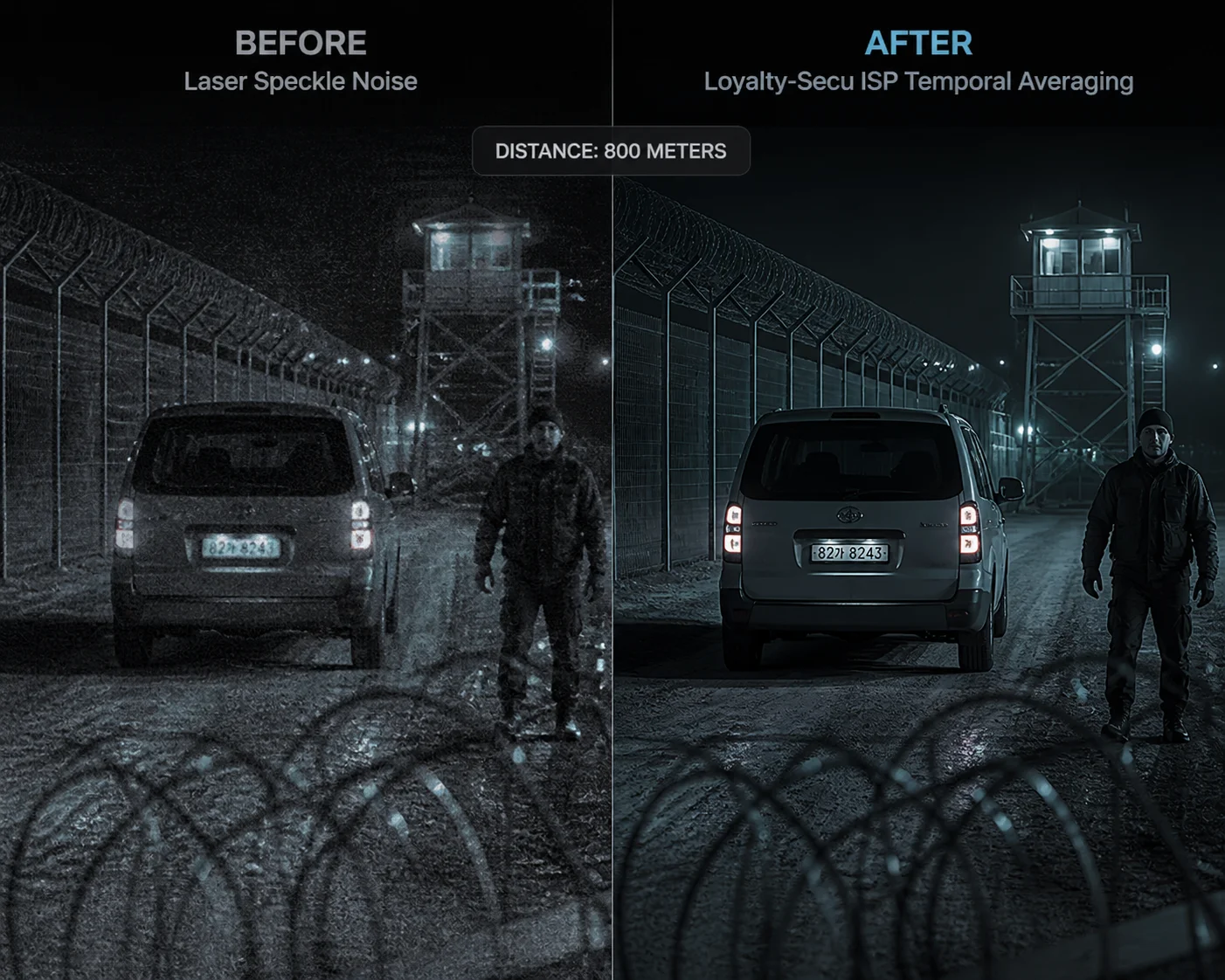
Laser speckle — that grainy, shimmering texture on the image — is one of the most frustrating problems in long-range laser surveillance. I have had customers blame the sensor, the lens, even the network, before realizing the laser itself was the cause.
Speckle is caused by coherent laser light reflecting off rough surfaces and creating random interference patterns on the sensor. We reduce it by using partially coherent laser sources, vibrating diffusers, and temporal averaging in the ISP 3, which together suppress speckle contrast below the visible threshold.
 laser speckle reduction long range surveillance
What Causes Speckle and Why It Matters
Laser light is coherent — all the waves are in phase. When this coherent light hits a rough surface (concrete, vegetation, gravel), each tiny surface feature reflects the light at a slightly different path length. These reflected waves interfere with each other and create a random bright-and-dark pattern called speckle 4. On your monitor, it looks like static noise layered on top of the real image.
The partial coherence length 6 of the laser source directly impacts speckle contrast — shorter coherence length means less speckle.
At long range, speckle is worse because:
- The beam travels farther and interacts with more atmospheric turbulence.
- The target surfaces are rougher relative to the spot size.
- The camera is zoomed in tight, so each speckle grain covers more pixels.
How We Suppress Speckle
There is no single magic fix. We use a combination of methods:
Hardware-Level Reduction
Our laser modules use a partially coherent source rather than a single-mode laser. This means the light has a shorter coherence length, which naturally reduces the contrast of speckle patterns. We also integrate a micro-vibrating element near the diffuser. This element shifts the speckle pattern slightly during each exposure frame. When the sensor integrates over the full exposure time, the shifting patterns average out and the speckle becomes invisible.
ISP-Level Reduction
On the image processing side, our camera firmware applies a temporal averaging filter that blends multiple short-exposure frames. This further smooths any residual speckle without blurring moving objects, because the algorithm only averages the static background regions.
Practical Impact
For a project like border surveillance or perimeter monitoring at 800 meters, speckle reduction is not optional. If you skip it, your operators will struggle to identify faces, license plates, or fence breaches. The image looks “alive” with noise even when nothing is moving. I have seen integrators lose contracts because the end user saw speckle on the demo and assumed the camera was defective.
When you test a sample unit, zoom to maximum and point the laser at a concrete wall at 200+ meters. If you see a shimmering, grainy texture that does not go away, the supplier has not addressed speckle. Walk away.
Can I Adjust the Laser Focus Manually to Correct Uneven Lighting in Specific Scenes?
Sometimes the automatic system gets it 90% right, but a specific scene — a narrow alley, a wide parking lot, a hillside — needs a manual tweak. I get this question a lot from experienced installers.
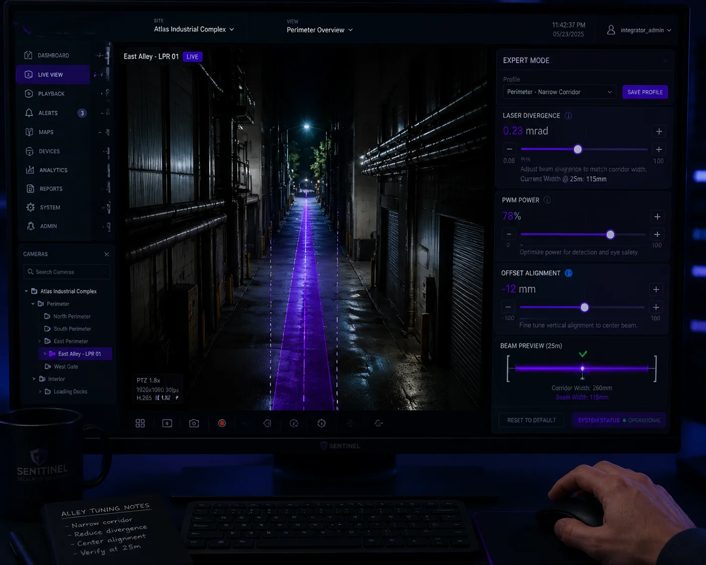
Yes. Our laser PTZ cameras offer an Expert Mode that lets you manually adjust the laser beam divergence angle, power output, and offset position. This gives installers direct control to fine-tune illumination for unusual scenes where the automatic algorithm may not perfectly match the field of view.
 manual laser focus adjustment PTZ camera
When Automatic Mode Is Not Enough
Our DSS (Digital Sync Slant) algorithm handles most situations well. It reads the current lens focal length and adjusts the laser beam angle to match. This zoom-laser synchronization (ZLID) 7 system is critical for uniform illumination.
But there are edge cases:
- Asymmetric scenes: A road that runs diagonally across the frame. One side is close, the other side is far. The auto mode illuminates evenly by distance, but the close side gets over-exposed by reflected light.
- High-reflectivity objects: A metal fence, a glass building, or a row of parked cars with shiny surfaces. The laser bounces back hard from these objects and creates local hot spots.
- Partial obstruction: A tree or pole blocks part of the laser beam, creating a shadow on one side of the image.
What You Can Adjust Manually
In Expert Mode, you get access to three key parameters:
| Parameter | What It Controls | Typical Range |
|---|---|---|
| Laser Divergence (Beam Width) | How wide the laser beam spreads | Narrow (0.5°) to Wide (15°+) |
| Laser Power (PWM) | The output intensity of the laser diode | 0% to 100% in 1% steps |
| Laser Offset (Alignment) | Shifts the laser beam left/right/up/down relative to the lens axis | ±2° in 0.1° steps |
Divergence Adjustment
If the image has dark edges, you widen the beam. If the center is washed out at close range, you also widen the beam and reduce power. For long-range targets, you narrow the beam to concentrate energy.
Power Adjustment
PWM linear dimming 9 is critical here. Cheap laser cameras only have “on” and “off.” Ours let you set any power level from 0% to 100%. If you are monitoring a scene at 200 meters and the auto mode is pushing 80% power, but the target has a white wall that reflects too much, you can manually drop to 40% and get a perfectly balanced image.
Offset Adjustment
This one is often overlooked. If the laser and the lens are not perfectly coaxial — which can happen after shipping, strong wind, or thermal expansion — the bright spot will not be centered in the frame. The offset adjustment lets you re-center it without physically touching the hardware. We also provide a Laser Calibration routine in the menu that automates this process. I recommend running it once after every installation and again after any severe weather event.
A Real-World Tip
For installers working on border or perimeter projects, I suggest starting with full auto mode, then switching to Expert Mode only for the preset positions that look uneven. Save the manual settings to each preset. This way, the camera uses optimized laser settings as it patrols between positions, without requiring the operator to adjust anything in real time.
Why Does My Current Laser Camera Have a “Flashlight” Effect With Dark Peripheral Areas?
This is the number one complaint I hear from integrators who bought cheap laser PTZ cameras. They call it the “flashlight effect,” and it kills project acceptance every time.
The flashlight effect happens because low-cost laser cameras use a bare point-source diode with no beam-shaping optics, and the laser beam angle does not change when the lens zooms. This means the Gaussian hot spot stays fixed while the lens FOV changes, creating a bright center circle surrounded by complete darkness.
 flashlight effect laser camera dark edges
The Two Root Causes
There are exactly two reasons this happens, and they usually occur together:
1. No Beam-Shaping Optics (Cheap Optical Design)
As I explained earlier, a raw laser diode outputs a Gaussian beam. Without a homogenizer, MLA, or DOE, the beam hits the scene with a sharp peak in the center. The camera sensor sees a circle of light that fades rapidly toward the edges. This is pure physics — it is not a defect you can fix with firmware.
Low-cost manufacturers skip beam-shaping optics to save $5-$15 per unit. That savings costs their customers thousands in failed installations and rework.
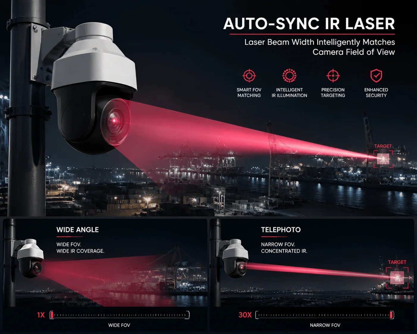
2. No Zoom-Laser Synchronization
This is the second — and often worse — problem. When you zoom the lens from wide angle to telephoto, the field of view narrows dramatically. If the laser beam angle stays the same, two things happen:
- At wide angle: The laser spot covers only a small portion of the wide FOV. The center is bright, everything else is black.
- At telephoto: The laser spot may be wider than the narrow FOV. The image looks okay, but you are wasting laser power illuminating areas outside the frame.
A proper ZLID (Zoom Laser IR Diode) design synchronizes the laser divergence angle with the lens focal length in real time. Our system uses a motorized focus element in the laser module that tracks the lens zoom position with 0.1° precision. The algorithm also adds a 5%-10% buffer zone, keeping the laser beam slightly wider than the lens FOV at all times. This eliminates dark edges completely.
How to Test for This Before You Buy
Here is a simple test procedure you can use when evaluating any laser PTZ sample:
- Set up the camera pointing at a flat wall or open field at night.
- Start at maximum wide angle. Take a screenshot.
- Zoom to 10x. Take a screenshot.
- Zoom to 20x. Take a screenshot.
- Zoom to maximum telephoto. Take a screenshot.
- Compare all four images side by side.
If the bright spot stays the same size in all four images while the FOV changes, the laser is not synchronized. Reject that unit.
If the bright spot smoothly adjusts to fill the frame at every zoom level, and the brightness is relatively even from center to edge, you have a properly designed system.
What If You Already Own a Bad Unit?
If you are stuck with a camera that has the flashlight effect, here are some emergency measures:
| Action | What It Does | Limitation |
|---|---|---|
| Enable HLC (High Light Compensation) | Suppresses the over-bright center pixels | Cannot add light to dark edges |
| Enable WDR / BLC | Balances exposure between bright and dark areas | Adds noise in dark regions |
| Reduce laser power manually | Lowers center brightness | Reduces effective range |
| Add external IR illuminators | Fills in the dark edges with supplemental light | Adds cost and installation complexity |
| Raise mounting height | Pushes the hot spot farther from the camera, reducing near-field reflection | Not always possible |
These HLC and BLC algorithms 8 are band-aids, not cures. The real solution is to replace the unit with one that has proper optical design and zoom-laser synchronization from the start.
The center-to-edge illuminance ratio 10 is the key specification — a good laser PTZ should maintain at least 60% edge illuminance relative to center.
At Loyalty-Secu, we have been building laser PTZ cameras since 2013. Every lesson from every failed competitor product that our customers replaced has gone into our optical and firmware design. We do not sell bare-diode laser cameras. Every unit ships with beam-shaping optics, DSS synchronization, and PWM linear dimming as standard. If you are tired of explaining flashlight effects to your end users, talk to us.
Conclusion
Uneven laser illumination is an optical design problem, not just a settings issue. Fix it at the source with proper beam shaping, zoom-laser synchronization, and smart ISP processing — or keep fighting the same complaints on every project.
1. Micro-lens array beam homogenization for laser diodes. ↩︎ 2. Gaussian beam optics and energy distribution profile. ↩︎ 3. Image Signal Processor temporal averaging for speckle reduction. ↩︎ 4. Laser speckle pattern formation and suppression methods. ↩︎ 5. Diffractive Optical Element (DOE) design for flat-top beams. ↩︎ 6. Partial coherence length impact on speckle contrast. ↩︎ 7. Zoom-laser synchronization (ZLID) system for PTZ cameras. ↩︎ 8. HLC and BLC algorithms for laser hot spot suppression. ↩︎ 9. PWM linear dimming for variable laser power control. ↩︎ 10. Center-to-edge illuminance ratio specification for laser PTZ. ↩︎