
I’ve seen too many dual-lens PTZ cameras fail at night because one lens blinds the other. It’s a real problem.
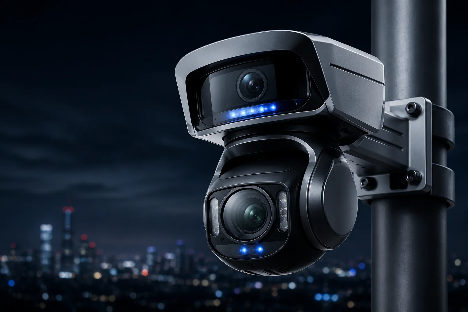
In our dual-lens PTZ system, we use physical shielding, spectral separation, and smart IR power control to stop infrared and laser light from bleeding between the panoramic lens and the tracking lens. This three-layer approach keeps both images clean, even in total darkness with high-power laser illumination active.
 dual lens PTZ camera night vision anti-halo design
Below, I’ll walk you through the exact methods we use — from hardware barriers to firmware logic — so you can understand how each layer works and why it matters for your night deployments.
Table of Contents
Is There a Physical Shield or an Internal Coating to Prevent IR Light From Bleeding Into the Other Lens?
I learned this the hard way: without a physical barrier, the IR fill light1 bounces off the dome glass and floods the other sensor. It ruins the image instantly.
Yes. We install industrial-grade black light-absorbing dividers between each lens module and its IR illuminator. We also apply multi-layer anti-reflective coatings on the inner surface of the protective dome glass to kill internal reflections before they reach the second sensor.
 physical IR shield between dual lenses PTZ camera
How Internal Reflection Creates the “Ghost Halo”
When IR light hits the inside of a dome cover, it can bounce multiple times before reaching a sensor that was never meant to receive it. This is called internal reflection2, and it creates a white fog or a half-moon arc on the image. In a dual-lens system, the risk doubles because you have two IR sources and two sensors sharing the same housing.
Our solution starts at the mechanical design level. Each lens sits inside its own optical chamber. The chambers are separated by a wall made of matte black anodized aluminum3. This material absorbs over 95% of stray IR light that hits it. The wall blocks any direct path between the panoramic IR LEDs and the PTZ sensor.
The Role of Anti-Reflective Coatings
The dome glass itself is another source of trouble. Standard glass reflects about 4% of light at each surface. With IR wavelengths (850nm or 940nm4), this reflection can be even stronger. We apply a multi-layer AR coating tuned specifically for the 800–950nm band. This drops the reflection rate below 0.5%.
Non-Coplanar Lens Placement
Beyond barriers and coatings, we physically offset the two lenses. The panoramic lens sits on top. The PTZ lens hangs below. This vertical separation increases the angle that stray light must travel to reach the wrong sensor. In practice, this means the IR from the panoramic module would need to bounce at least three times before it could enter the PTZ optical path — and each bounce loses over 90% of its energy.
| Protection Layer | What It Does | Effectiveness |
|---|---|---|
| Black absorbing divider wall | Blocks direct IR path between modules | >95% absorption |
| AR-coated dome glass | Reduces internal surface reflections | <0.5% reflection at 850nm |
| Vertical lens offset (non-coplanar) | Increases bounce angle for stray light | 3+ bounces required to cross |
Does the Firmware Use an “Anti-Halo” Algorithm to Clean Up the Image During High-Power Laser Use?
I’ve tested cameras where the laser looked great on paper but turned the image into a white mess in the field. Firmware matters just as much as hardware.
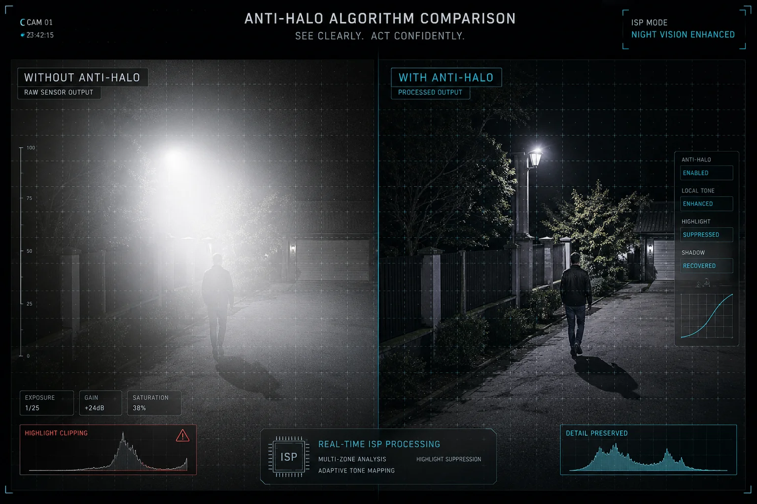
Yes. Our firmware runs a real-time anti-halo algorithm that detects over-exposed zones caused by laser reflection, then applies localized tone mapping and multi-frame synthesis to suppress the bright spots while keeping shadow detail intact.
 anti-halo algorithm firmware night vision PTZ camera
How the Algorithm Detects Halo Zones
The ISP (Image Signal Processor)5 on our edge AI chip6 divides each frame into a grid of small regions. It measures the brightness histogram of each region independently. When a region exceeds a set threshold — say, 90% of pixels are above 240 on a 0–255 scale — the firmware flags it as a potential halo zone.
Once flagged, the system does not simply reduce global exposure. That would darken the entire image and lose detail in the shadows. Instead, it applies localized gain reduction only to the affected region. This is similar to how WDR (Wide Dynamic Range)7 works, but it is specifically tuned for the spectral signature of laser reflection.
Multi-Frame Synthesis for Detail Recovery
In extreme cases — for example, when the laser hits a reflective surface like a metal fence at 200 meters — a single frame cannot capture both the bright spot and the dark background. Our firmware captures two exposures in rapid sequence: one short exposure to preserve detail in the bright zone, and one long exposure to capture the dark surroundings. It then merges them into a single output frame.
This happens at 25fps with no visible lag. The user sees a clean, balanced image.
Polarization Filtering at the Hardware Level
The anti-halo system also works hand-in-hand with a hardware polarization filter on the PTZ lens. Our laser emits light in a specific polarization direction. The filter on the PTZ sensor is aligned to accept only that polarization. Random IR scatter from the panoramic module — which is unpolarized — gets blocked by the filter before it even reaches the sensor.
| Halo Scenario | Firmware Response | Result |
|---|---|---|
| Laser hits reflective surface (metal, glass) | Localized tone mapping + short exposure blend | Bright spot compressed, background preserved |
| Panoramic IR scatter enters PTZ path | Polarization filter blocks unpolarized light | Scatter eliminated at hardware level |
| Near-field object over-illuminated | Smart IR reduces power to affected zone | Even brightness across frame |
Can I Adjust the IR Intensity for Each Lens Independently to Balance the Nighttime Exposure?
I’ve had customers ask me: “Can I turn down the panoramic IR without affecting the PTZ laser?” The answer matters because every site is different.
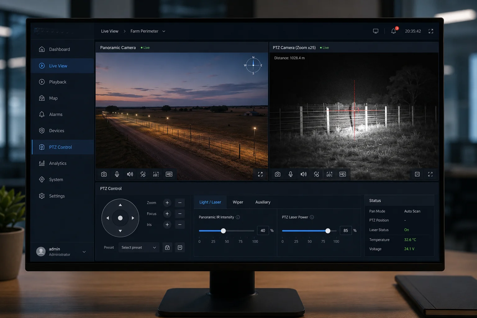
Yes. Each lens module has its own independent IR/laser power control. You can adjust the panoramic IR intensity and the PTZ laser intensity separately through the web interface, NVR menu, or CGI commands — from 0% to 100% in fine steps.
 independent IR intensity control dual lens camera interface
Why Independent Control Matters in the Field
Every installation site has different conditions. A farm perimeter might have zero ambient light, so you need full IR power on both lenses. A warehouse yard might have some pole-mounted lights, so the panoramic lens only needs 40% IR while the PTZ still needs full laser for long-range tracking.
If both lenses share a single IR power setting, you cannot optimize for these differences. You either over-illuminate the near field (causing bloom and wasted power) or under-illuminate the far field (losing tracking detail). Independent control solves this.
How the Smart IR System Works Automatically
While manual control is available, most users rely on our Smart IR8 auto-adjustment. Here is how it works:
- The firmware reads the average brightness of each image independently.
- If the panoramic image is too bright (near-field objects reflecting too much IR), it reduces panoramic IR power.
- If the PTZ image is too dark (target is far away), it increases laser power and narrows the beam angle.
- These adjustments happen every 100 milliseconds, faster than the human eye can notice.
You can also set upper and lower limits for each channel. For example, you might tell the system: “Never let the panoramic IR go above 60%, but allow the PTZ laser to use up to 100%.” This gives you automatic optimization within boundaries you define.
Manual Override via CGI Commands
For advanced integrators like David who manage hundreds of cameras through a VMS, we provide direct CGI command access. A simple HTTP GET request can set the IR power of either channel:
GET /cgi-bin/param.cgi?action=set&channel=0&ir_power=50
GET /cgi-bin/param.cgi?action=set&channel=1&laser_power=80
This allows scripted control. You can tie IR power changes to time schedules, alarm events, or even weather sensor inputs from your SCADA system.
Power Consumption Comparison
| IR Setting | Panoramic Module Power Draw | PTZ Laser Module Power Draw | Total System Draw |
|---|---|---|---|
| Both at 100% | ~8W | ~15W | ~23W + motor |
| Panoramic 50%, Laser 100% | ~4W | ~15W | ~19W + motor |
| Panoramic 30%, Laser 60% | ~2.4W | ~9W | ~11.4W + motor |
| Both at 0% (daytime) | 0W | 0W | ~5W (base + motor standby) |
For solar-powered deployments, reducing IR power during partial-moon nights can extend battery life by 2–3 hours. This is a real advantage when your panel only charges for 5–6 hours in winter.
Will the Laser’s Beam Angle Affect the Panoramic Lens’s Human Detection Accuracy?
I’ve been asked this question by integrators who worry that the laser creates false triggers on the panoramic lens. It’s a valid concern.
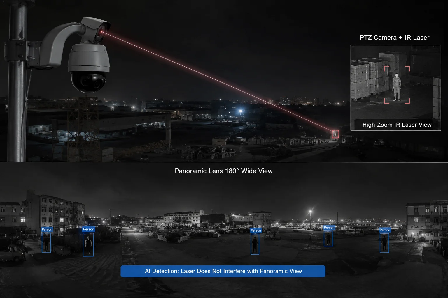
In normal operation, the laser does not affect the panoramic lens’s AI detection accuracy because the laser beam is aimed forward from the PTZ module, not sideways toward the panoramic sensor. The physical offset and beam direction keep the laser energy out of the panoramic field of view.
 laser beam angle panoramic lens AI detection PTZ camera
Understanding the Geometry
The PTZ laser points wherever the PTZ lens points. When the PTZ is tracking a person at 300 meters, the laser beam is a narrow cone (typically 1–3 degrees wide) aimed at that distant target. The panoramic lens, meanwhile, looks at a wide 180-degree scene. The laser beam occupies a tiny fraction of the panoramic field — and it’s pointed away from the panoramic sensor, not toward it.
The only scenario where the laser could affect the panoramic image is if the laser hits a highly reflective surface (like a mirror or a car windshield) that bounces light directly back toward the panoramic lens. This is rare, but our firmware handles it.
How AI Detection Stays Accurate
Our human detection algorithm runs on the panoramic lens feed. It uses a deep learning model trained on millions of human silhouettes in various lighting conditions — including scenes with IR illumination artifacts. The model has learned to distinguish between:
- A real human shape (head, shoulders, legs, movement pattern)
- A bright IR reflection (static, no human shape, no movement pattern)
Even if a small bright spot appears in the panoramic image from laser scatter, the AI does not classify it as a person. It lacks the shape features and motion characteristics that trigger a detection event.
Beam Angle Synchronization
Our laser uses a motorized zoom lens that synchronizes with the PTZ optical zoom. When the PTZ is at 1X, the laser spreads wide to cover the full field. When the PTZ zooms to 40X, the laser narrows to a tight beam. This synchronization means the laser always illuminates exactly what the PTZ sees — nothing more, nothing less.
This tight control prevents the laser from spraying light across the panoramic lens’s field of view. The laser energy stays concentrated on the PTZ target area.
Edge Case: Close-Range Tracking
When the PTZ tracks a person at close range (under 20 meters), the laser angle is wider and the target is within the panoramic lens’s near field. In this case, the Smart IR system automatically reduces laser power because the target is already well-lit by the panoramic IR. The firmware logic is simple: if the target is close, you don’t need a powerful laser. This prevents both over-exposure on the PTZ image and any potential scatter into the panoramic sensor.
Conclusion
Our dual-lens PTZ cameras solve IR/laser halo interference through physical barriers, independent power control, polarization filtering, and smart firmware — giving you clean night images on both channels without compromise.
1. Overview of infrared illuminators used in night vision. ↩︎ 2. Explanation of internal reflection and its effects in optical systems. ↩︎ 3. Process that increases corrosion resistance and can provide a matte light-absorbing finish. ↩︎ 4. Common wavelengths for infrared illumination in surveillance cameras. ↩︎ 5. Role of image signal processors in camera image quality enhancement. ↩︎ 6. Overview of edge AI hardware for real-time processing in cameras. ↩︎ 7. How WDR technology handles high-contrast scenes in imaging. ↩︎ 8. Explanation of smart IR technology that automatically adjusts infrared intensity. ↩︎