
I’ve seen installers bolt heavy PTZ cameras onto poles without checking a single load spec. One storm later, that camera is on the ground.
Matching camera weight to U.S. pole mount safety loads requires more than checking pounds. You must calculate the Effective Projected Area (EPA), apply AASHTO wind speed ratings, and verify the total load stays within 80% of the pole’s rated capacity at your install height.
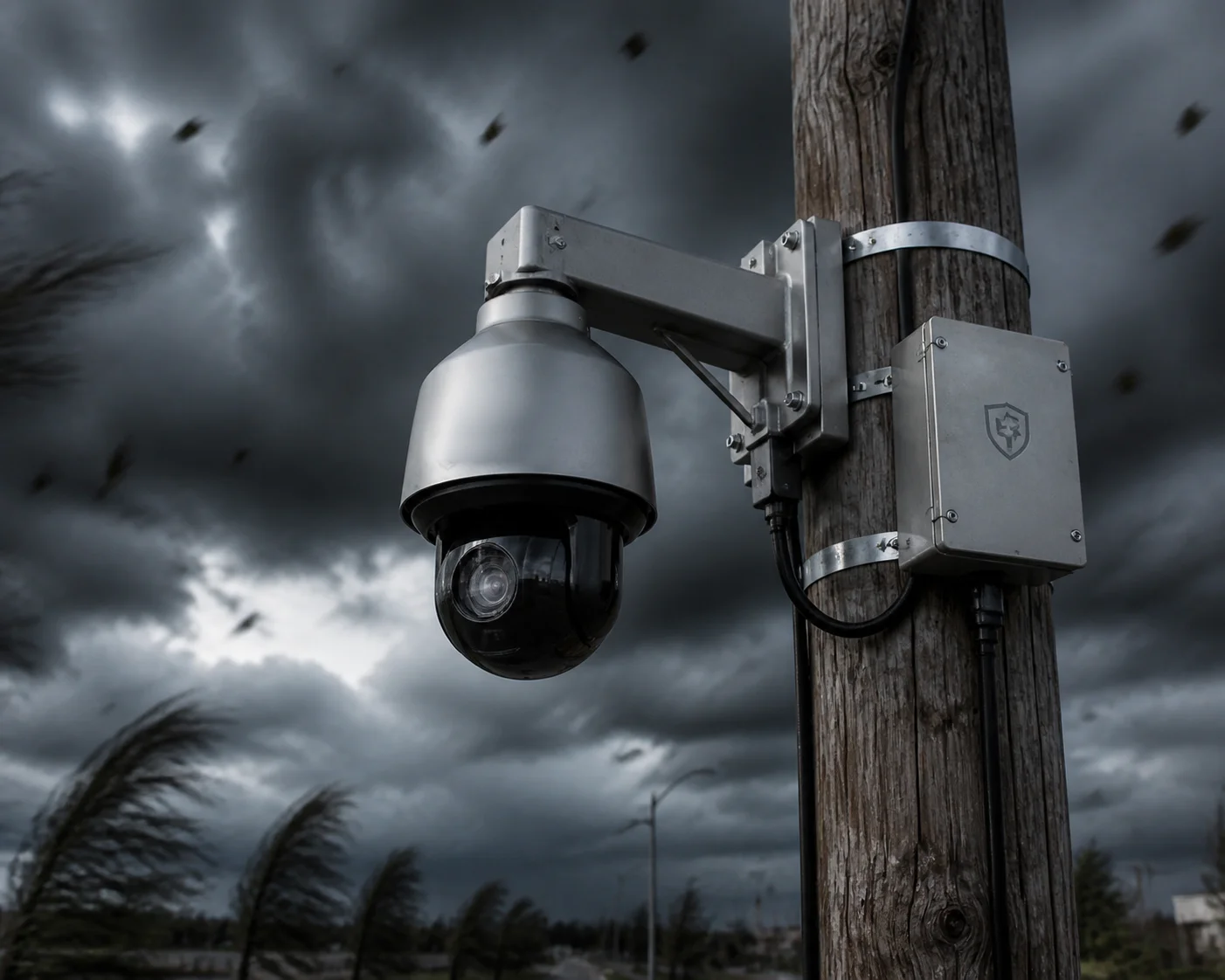 PTZ camera mounted on U.S. standard pole with safety hardware
Weight alone tells you almost nothing about whether your pole can handle the camera. Wind turns a 10-pound PTZ into a force that pulls sideways with hundreds of pounds of pressure. Below, I break down the exact calculations, standards, and hardware specs you need to get this right — especially if you are importing PTZ cameras from China and deploying them in U.S. wind zones.
Table of Contents
How Do I Calculate the Wind Load (Drag Coefficient) for My 40X PTZ at 30 Feet?
I mounted a 40X PTZ at 30 feet once without running wind load numbers. The bracket bent in the first big storm. Never again.
To calculate wind load, multiply the wind pressure at your install height by the camera’s drag coefficient and its frontal area. Or, use the manufacturer’s EPA value directly. EPA already accounts for drag coefficient, so you can plug it straight into standard wind force formulas.
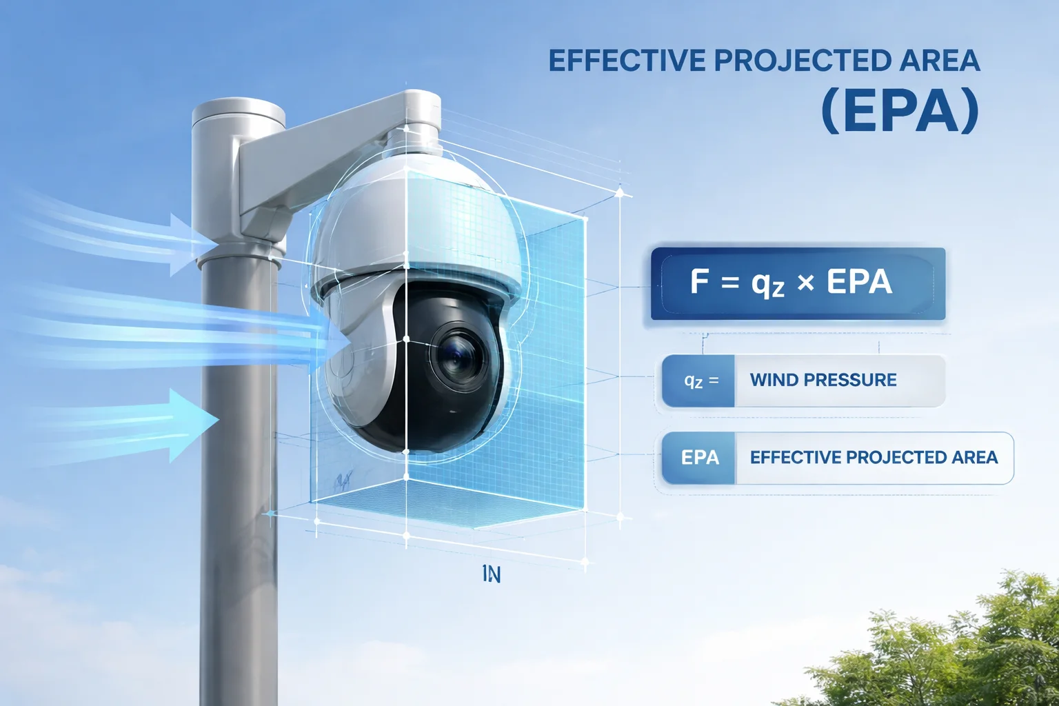 40X PTZ camera wind load calculation on tall pole
What Is EPA and Why It Matters More Than Weight
EPA stands for Effective Projected Area. It measures how much “sail effect” your camera creates in the wind. A large 40X PTZ camera with a big housing catches more wind than a small dome. EPA combines the frontal area with the drag coefficient into one number. This saves you a step in calculations.
Most U.S. pole manufacturers list their poles by EPA capacity at a given wind speed. For example, a 25-foot SteadyMax pole might allow 2.9 square feet of EPA at 150 mph wind. Your camera, bracket, junction box, and any other accessories all add to the total EPA on that pole. For a complete understanding of EPA calculations in traffic and surveillance applications, refer to the AASHTO LRFD Specifications for Structural Supports 1.
The Basic Wind Load Formula
Here is the simplified formula:
$$F = q_z \times C_d \times A$$
Where:
- F = wind force on the camera (lbs)
- q_z = wind pressure at height z (psf, pounds per square foot)
- C_d = drag coefficient (typically 1.0–1.5 for cylindrical/spherical shapes)
- A = frontal area of the camera and bracket (sq ft)
If the manufacturer gives you EPA, then EPA = C_d × A. So the formula becomes:
$$F = q_z \times EPA$$
Wind pressure q_z changes with height. At 30 feet, the wind pressure is higher than at 15 feet. ASCE 7 tables give you exact values. The ASCE 7 standard for wind loads on structures 2 is the authoritative source for these pressure coefficients. For a rough estimate, at 100 mph wind speed, q_z at 30 feet is about 21.4 psf.
A Practical Example
Let’s say your 40X PTZ has these specs:
| Parameter | Value | Source |
|---|---|---|
| Camera net weight | 6.8 kg (15 lbs) | Manufacturer datasheet |
| Bracket + junction box weight | 2.3 kg (5 lbs) | Measured |
| Camera frontal area | 0.55 sq ft | Measured from housing dimensions |
| Drag coefficient (C_d) | 1.2 | Estimated for spherical PTZ dome |
| EPA (C_d × A) | 0.66 sq ft | Calculated |
| Wind pressure at 30 ft (100 mph) | 21.4 psf | ASCE 7 reference |
| Wind force (F) | 14.1 lbs | q_z × EPA |
At 100 mph, your camera pushes 14.1 lbs of sideways force on the pole. That sounds small. But this force acts at 30 feet high. So the bending moment at the pole base is 14.1 × 30 = 423 ft-lbs. Now add the bracket EPA, antenna EPA, and any other equipment on the pole. The numbers add up fast.
What If Your Chinese PTZ Supplier Does Not Provide EPA?
Most Chinese PTZ manufacturers do not list EPA in their datasheets. I deal with this every week. Here is what you can do. Ask the supplier for the housing dimensions — height, width, depth, and dome diameter. Then estimate the frontal area yourself. For a spherical PTZ dome, use the circle area formula (π × r²). For a bullet-style camera, use width × height. Multiply by a drag coefficient of 1.2 for round shapes or 1.5 for flat/box shapes. This gives you a conservative EPA estimate.
At Loyalty-Secu, we provide EPA data and full mechanical drawings to our integrator partners. If your current supplier cannot give you this, that is a red flag.
Will the Standard Mounting Bracket Survive a 100 mph Wind Gust in a Coastal Zone?
I got a call from an integrator in Florida after Hurricane Ian. Three cameras fell off poles. The brackets failed. The cameras were fine. The brackets were the weak link.
A standard lightweight bracket will not survive 100 mph gusts in coastal zones. You need a heavy-duty bracket rated for at least 5x the total static load, made from 316 stainless steel, and designed for AASHTO coastal wind speed categories of 120–150 mph.
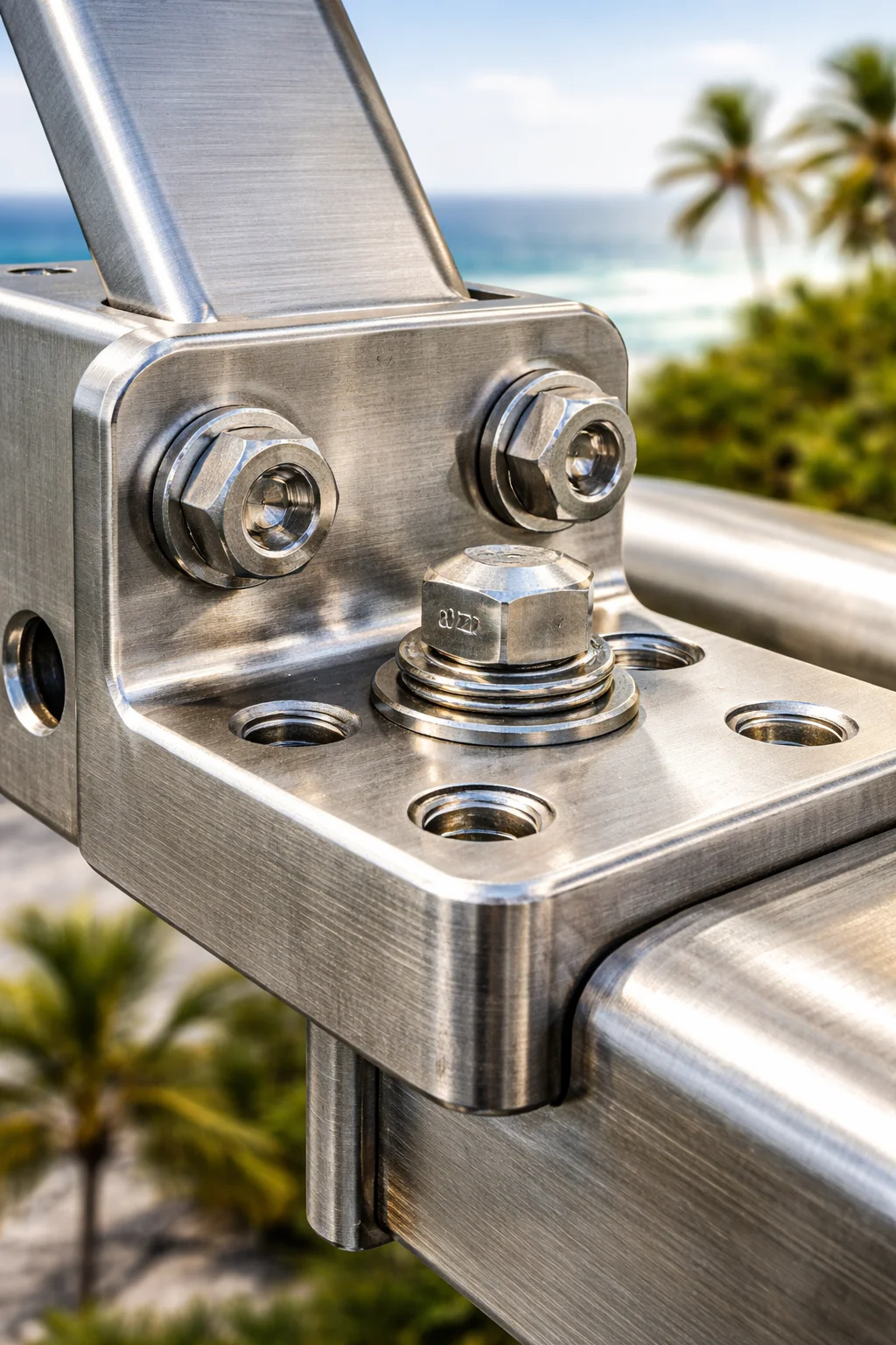 Heavy-duty stainless steel PTZ bracket for coastal wind zones
Coastal Zones Demand Higher Wind Speed Ratings
In the U.S., coastal areas face much higher design wind speeds than inland areas. The ASCE 7 wind maps divide the country into zones. Inland Texas might require 90–100 mph ratings. But coastal Florida, the Gulf Coast, or the Outer Banks of North Carolina can require 120–150 mph ratings. Some areas near the coast need 170 mph or higher. The FEMA coastal wind speed zone maps 3 are essential references for determining local requirements.
A “standard” mounting bracket from a generic supplier is usually tested only for static weight — maybe 20 or 30 pounds. Nobody tests it for lateral wind force at 150 mph. That is the gap where failures happen.
AASHTO and Fatigue Loading
AASHTO — the American Association of State Highway and Transportation Officials — publishes standards for structural supports used in traffic and surveillance applications. If your camera sits on a pole next to a highway or bridge, you must also consider fatigue loading. Large trucks create air blasts as they pass. This causes repeated vibration at the bracket joint. Over months, this vibration can crack welds or loosen bolts. The AASHTO fatigue design requirements for support structures 4 provide detailed guidance.
For highway-adjacent installations, AASHTO requires fatigue analysis for Category I structures. This means your bracket must handle not just peak wind, but also thousands of small vibration cycles without cracking.
What to Look for in a Bracket
Here is what I check before I approve a bracket for any coastal project:
- Material: 316 stainless steel for salt spray resistance. Never use painted carbon steel near the coast. It will rust through in 18–24 months.
- Wall thickness: Minimum 3mm for the main arm. Thicker is better.
- Bolt pattern: At least four M10 or 3/8″ bolts connecting the bracket to the pole adapter. Two bolts are not enough.
- Anti-rotation pin or set screw: Prevents the bracket from spinning around the pole under wind torque.
- Safety cable attachment point: A dedicated lug or loop where you can attach a secondary safety wire.
If you buy a PTZ camera from China and it comes with a lightweight stamped-metal bracket, replace that bracket with something rated for your wind zone. The camera itself is usually fine. The bracket is almost always the failure point.
Match the Bracket to the Pole, Not Just the Camera
Many integrators match the bracket to the camera weight and stop there. But the bracket also connects to the pole. The connection method matters. On round poles, stainless steel banding (strapping) is the standard. The band must be at least 1/2 inch (12.7 mm) wide and 0.030 inches thick. Use 316 stainless steel in coastal areas. Tighten the worm gear clamp to the manufacturer’s recommended torque. If you under-tighten, the camera can slide down or rotate on the pole during a storm.
Can I Get a Structural Stress Analysis Report for the Camera’s Mounting Joints?
I once asked a budget supplier for a stress analysis report. They sent me a marketing PDF with no engineering data. That told me everything I needed to know about their quality.
Yes, you can and should request a structural stress analysis report. A proper report covers static load, wind-induced bending moment, bolt shear stress, and weld joint capacity. Any serious manufacturer or structural engineer can provide one based on AISC or AASHTO methods.
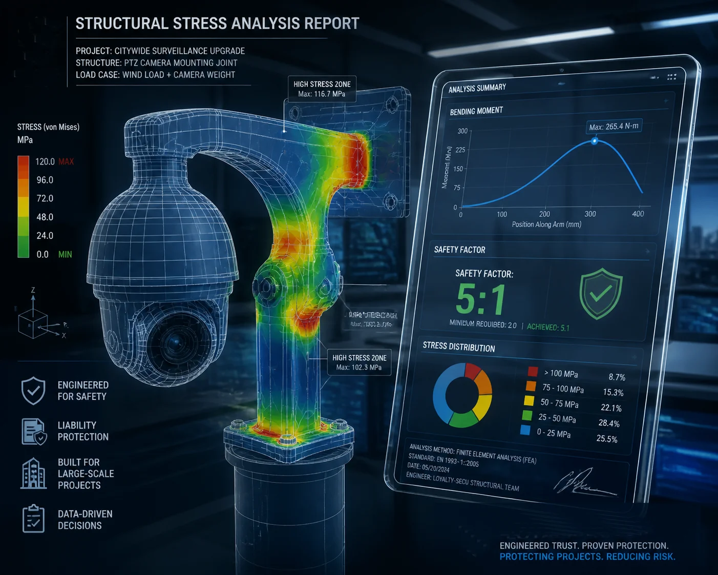 Structural stress analysis report for PTZ camera mounting joint
Why You Need This Report
A stress analysis report is not just paperwork. It protects you legally and financially. If a camera falls off a pole and injures someone, the first question a lawyer will ask is: “Did you verify the mounting system was rated for the conditions?” Without documentation, you carry all the liability.
In many U.S. jurisdictions, especially for government or DOT projects, you must submit engineering calculations as part of the permit application. The building inspector will not approve your install without them.
What a Good Report Should Include
A complete structural stress analysis for a PTZ mounting system should cover at least these items:
- Load inputs: Camera weight, bracket weight, accessories weight, EPA values, design wind speed, install height, and gust factor.
- Bending moment at the mounting joint: This is usually the critical failure mode. The joint where the bracket meets the pole adapter sees the highest stress.
- Bolt shear and tensile stress: Each bolt must handle its share of the load. The report should show the calculated stress versus the bolt’s rated capacity.
- Weld capacity (if applicable): If the bracket uses welded joints, the report should verify weld size and type against the applied forces.
- Safety factor: The report should state the safety factor for each critical component. A minimum of 4:1 is standard for overhead equipment per OSHA guidelines. Many specifiers require 5:1.
For reference, the American Institute of Steel Construction (AISC) steel construction manual 5 provides the foundational calculation methods for structural steel components used in mounting systems.
How to Get One
You have three options:
- Ask your camera or bracket manufacturer. Reputable manufacturers have this data. At Loyalty-Secu, we can provide mechanical load documentation for our brackets and PTZ housings.
- Hire a licensed structural engineer (PE). For large projects or DOT work, this is often required. A PE will stamp the calculations. This stamp carries legal weight.
- Use the pole manufacturer’s data. Companies like StrongPoles publish detailed load tables. If your equipment falls within their rated EPA and weight limits, their published data serves as the structural verification.
| Report Component | What It Tells You | Why It Matters |
|---|---|---|
| Bending moment at joint | Maximum torque the joint can handle | Prevents bracket arm snapping in wind |
| Bolt shear stress | Whether bolts can take the sideways force | Prevents bolt failure and camera drop |
| Weld capacity | Strength of welded connections | Prevents cracking at weld seams |
| Safety factor | How much margin exists above rated load | Meets OSHA and AASHTO requirements |
| Fatigue life estimate | How many load cycles before failure | Critical for highway and bridge installs |
Do not skip this step. A $200 engineering review can save you from a $200,000 liability claim.
What Is the Recommended Safety Cable Thickness for Heavy Industrial PTZ Cameras?
I always install safety cables. Even on brackets I trust. Because brackets do not fail slowly — they fail all at once, and the camera drops 30 feet onto whatever is below.
For heavy industrial PTZ cameras weighing 8–15 kg (18–33 lbs) with a 5:1 safety factor, use a 316 stainless steel safety cable with a minimum diameter of 3/16 inch (4.8 mm). This provides a rated breaking strength of approximately 800–1,000 lbs, which far exceeds the static load requirement.
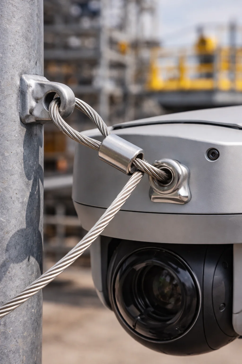 Stainless steel safety cable securing PTZ camera on pole
Why a Safety Cable Is Not Optional
In the U.S., OSHA requires a secondary retention system for any equipment mounted overhead in areas where people may walk or work below. A safety cable is the simplest way to meet this requirement. If the main bracket fails — from corrosion, metal fatigue, or a loose bolt — the safety cable catches the camera before it falls. The OSHA overhead equipment retention requirements (29 CFR 1910.66) 6 apply to permanently installed surveillance equipment at height.
This is not theoretical. I have personally seen cameras drop from poles after ice storms, after bracket corrosion, and after installation errors. In every case, the ones with safety cables stayed on the pole. The ones without became projectiles.
How to Size the Safety Cable
The sizing formula is straightforward:
$$Required\ Cable\ Strength = (Camera\ Weight + Bracket\ Weight + Accessories) \times Safety\ Factor$$
For a typical heavy PTZ setup:
- Camera: 15 lbs
- Bracket: 5 lbs
- Accessories (junction box, sunshield): 3 lbs
- Total: 23 lbs
- Safety factor: 5x
- Required cable strength: 115 lbs minimum
A 3/16-inch 316 stainless steel cable has a breaking strength around 900 lbs. That gives you nearly an 8:1 margin on a 5:1 requirement. This is good. You want extra margin because the cable must also absorb the shock load if the camera suddenly drops and the cable catches it. Dynamic shock loads can be 2–3 times higher than static loads.
Cable Material and Hardware
| Component | Recommended Spec | Notes |
|---|---|---|
| Cable material | 316 stainless steel, 7×19 construction | 7×19 is flexible and strong; 316 resists salt corrosion |
| Cable diameter | 3/16 inch (4.8 mm) minimum | For cameras up to 33 lbs total system weight |
| Thimbles | 316 stainless steel | Protects cable from sharp bends at connection points |
| Ferrules / swage sleeves | Copper or 316 stainless | Must be properly crimped with a swaging tool, not just clamped |
| Attachment point on pole | Through-bolt or welded eye bolt | Must be independent of the main bracket |
For proper cable termination techniques, refer to the Wire Rope Technical Board handbook on swaging and crimping 7.
Installation Tips
A few rules I follow on every job:
- Keep the cable short. The cable should allow no more than 6–12 inches of free fall before catching the camera. A longer cable means a bigger shock load.
- Attach the cable to the pole, not to the bracket. If the bracket fails, the cable must stay connected to something solid. Use a separate through-bolt or a wrap-around-pole method.
- Inspect annually. Even 316 stainless steel can degrade over time, especially in industrial environments with chemical exposure. Check for broken strands, corrosion, and loose ferrules.
- Loop through the camera housing. Many PTZ cameras have a safety cable attachment point on the housing. Thread the cable through it. If there is no attachment point, loop the cable around the mounting base of the camera and secure it with a properly swaged loop.
For guidelines on stainless steel cable inspection and retirement criteria, see the National Association of Corrosion Engineers (NACE) SP0177 standard for marine and coastal atmospheres 8.
At Loyalty-Secu, all of our heavy-duty outdoor PTZ cameras include a safety cable attachment point on the housing. We also provide recommended cable specs in our installation guides. If your current PTZ supplier does not offer this, ask them to add it. It is a small feature that prevents serious accidents.
Conclusion
Stop matching by weight alone. Calculate EPA, check local wind speeds, apply a 5:1 safety factor, and always install a 316 stainless steel safety cable. For additional guidance on pole selection, refer to the SteadyMax pole load capacity tables for PTZ installations 9. When importing cameras from China, the American National Standards Institute (ANSI) T1.319 telecom pole mounting standard 10 provides useful reference loads.
1. AASHTO LRFD specifications for structural supports of surveillance equipment. ↩︎ 2. ASCE 7 wind load calculations for structures at varying heights. ↩︎ 3. FEMA coastal wind speed zone maps for building code compliance. ↩︎ 4. FHWA AASHTO fatigue design requirements for highway support structures. ↩︎ 5. AISC steel construction manual for structural load calculations. ↩︎ 6. OSHA 29 CFR 1910.66 overhead equipment secondary retention requirements. ↩︎ 7. Wire Rope Technical Board manual for cable swaging and termination. ↩︎ 8. NACE SP0177 corrosion standards for stainless steel in marine environments. ↩︎ 9. SteadyMax pole load capacity tables for PTZ camera installations. ↩︎ 10. ANSI T1.319 telecom pole mounting standard reference loads. ↩︎