
I have seen too many off-grid camera system1 fail — not because of bad hardware, but because someone bolted the antenna right behind a steel bracket.
Yes, the solar panel bracket layout can cause signal shading and block 4G reception. Metal frames, mounting arms, and large panel surfaces create physical barriers and reflections that weaken or distort the 4G signal path between your antenna and the cell tower. Proper antenna placement and clearance are essential.
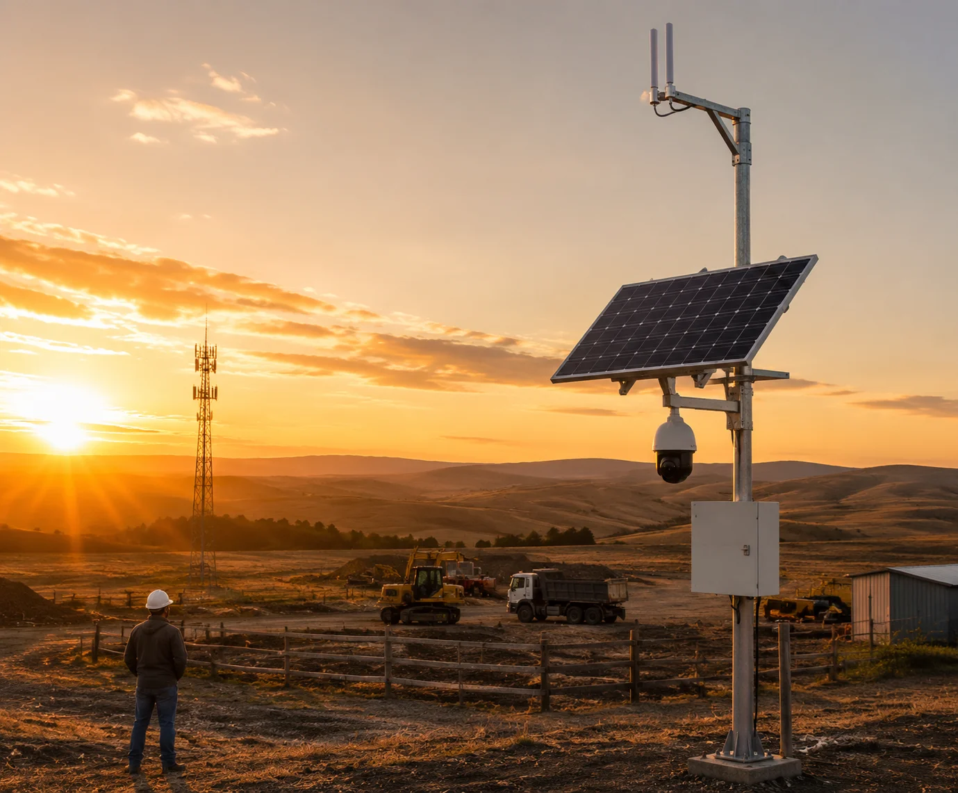
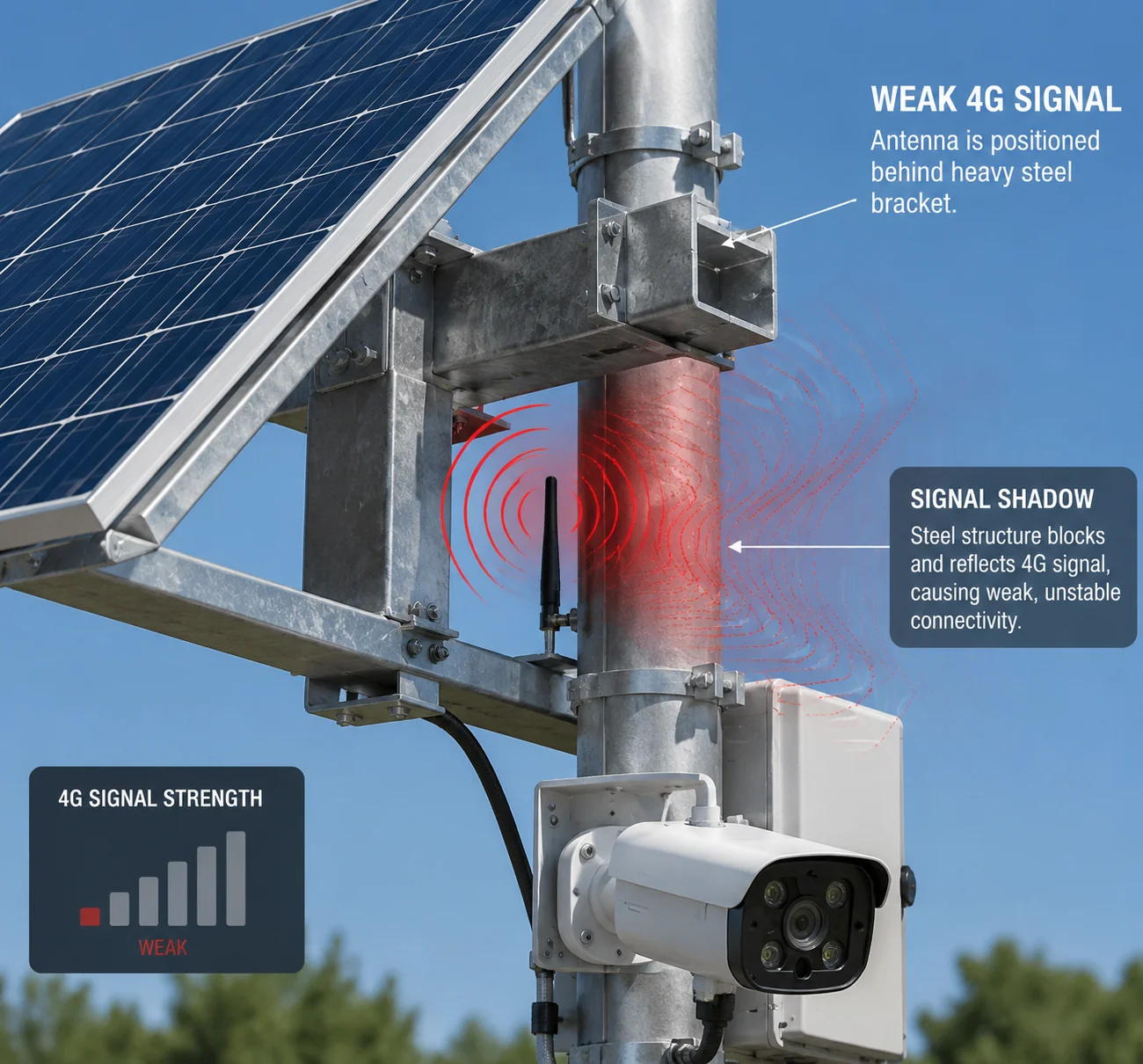 Solar panel bracket layout and 4G antenna signal shading
In this article, I will walk you through exactly how to position your antennas, how far they need to be from metal surfaces, whether the mounting arm acts as a reflector, and whether you can relocate antennas to the top of the panel. Every tip here comes from real field deployments. Let’s get into it.
Table of Contents
How Do I Position the Antennas Relative to the Large Solar Panel to Avoid Interference?
I have personally debugged systems where the signal dropped 10 dB just because the antenna sat 5 inches below the panel edge. That is the difference between a stable live stream and a frozen screen.
Position your 4G antennas above the highest point of the solar panel by at least 15 cm (6 inches). Keep the antenna at least 30 cm (12 inches) away from any metal frame or bracket. This gives the antenna a clear 360-degree sightline to nearby cell towers.
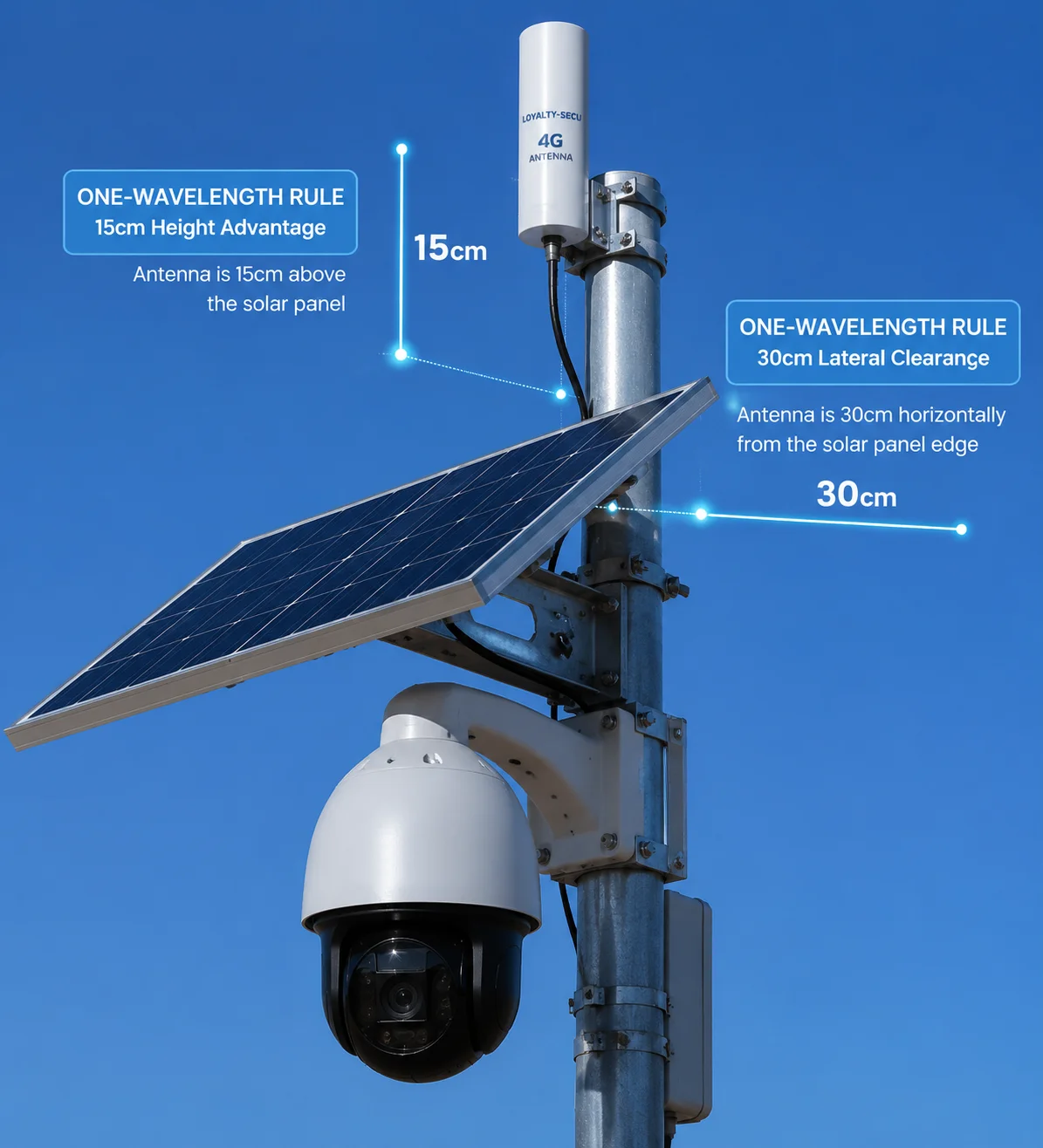 Antenna positioning relative to solar panel for 4G signal
Why Height Matters More Than You Think
4G and LTE signals travel as radio waves. They move in straight lines from the cell tower to your antenna. If a big metal solar panel sits between the tower and your antenna, the signal gets blocked. It is that simple.
Think of it like standing behind a wall and trying to hear someone talking on the other side. You might catch some sound, but it is muffled. The same thing happens with radio waves and metal surfaces. The panel acts like a wall for your signal.
The key rule is this: your antenna must be higher than the panel. When the antenna sits above everything else on the pole, it has a clear path in every direction. No metal is in the way. No frame is casting a “signal shadow.”
The One-Wavelength Rule
There is a simple physics rule that matters here. Your antenna should be at least one full wavelength away from any large metal surface. Different 4G band2 use different wavelengths. Here is a quick reference:
| 4G Band | Frequency | Wavelength (λ) | Minimum Distance from Metal |
|---|---|---|---|
| B13 / B14 | 700 MHz | ~43 cm | 40–45 cm |
| B2 / B4 / B66 | 1700–1900 MHz | ~16–18 cm | 18–20 cm |
| B41 (CBRS) | 2500 MHz | ~12 cm | 12–15 cm |
If you are deploying in the US or Canada, your system likely uses Band 2, Band 4, Band 13, or Band 66. For Band 13 at 700 MHz, the wavelength is about 43 cm. So your antenna needs to be at least 40 cm away from the nearest metal edge. For higher bands like B4 or B66, the wavelength is shorter, so you can get a bit closer — but I still recommend keeping at least 30 cm of clearance as a safe baseline.
What Happens If You Ignore This?
I have seen installers mount the antenna directly on the back of the solar panel frame. The result? Signal strength dropped from -75 dBm to -95 dBm. The camera could still “connect,” but video streaming became impossible. Packet loss hit 30%. The client called it “broken.” It was not broken. It was just badly placed.
Practical Tip for Tight Spaces
If your pole is short and you cannot get the antenna above the panel, use a pigtail extension cable3. Route the cable up through the bracket and mount the antenna at the very top of the pole using an L-shaped stainless steel bracket. We provide these brackets with our solar PTZ kits at Loyalty-Secu. The antenna points straight up, clear of all metal, and the signal stays strong.
Does the Metal Mounting Arm Act as a “Reflector” That Distorts the 4G Signal?
I once spent two hours on a video call with an integrator in Texas who could not figure out why his signal kept dropping every afternoon. Turned out the large aluminum mounting arm was bouncing the signal around like a mirror.
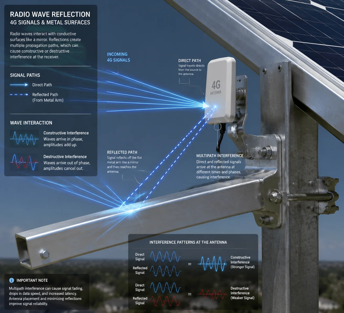
Yes, a metal mounting arm can act as a reflector. It bounces radio waves in unintended directions, creating multipath interference. This does not always kill the signal, but it causes data errors, slow speeds, and unstable video streams — even when the signal bar looks fine.
 Metal mounting arm reflecting 4G signal causing multipath interference
Understanding Multipath Interference
When a radio wave hits a flat metal surface, it bounces off. The reflected wave then arrives at the antenna a tiny fraction of a second after the direct wave. Your 4G modem now receives two copies of the same signal — one direct, one reflected. These two copies interfere with each other. Sometimes they add up and make the signal stronger. Sometimes they cancel each other out and make it weaker. This is called multipath interference.
The tricky part is that multipath problems do not always show up as “no signal.” Your phone or modem might still show 3 or 4 bars. But the actual data throughput drops. Video frames freeze. Uploads fail. The system looks connected but performs terribly.
Which Parts Cause the Most Reflection?
Not all parts of the bracket are equal. Here is a breakdown:
| Component | Material | Reflection Risk | Why |
|---|---|---|---|
| Solar panel backsheet | Aluminum / glass | High | Large flat surface, strong reflector |
| Main mounting arm | Galvanized steel | Medium-High | Long metal bar near the antenna |
| Pole clamp | Steel | Low-Medium | Small surface area |
| Cable clips / bolts | Stainless steel | Low | Too small to cause meaningful reflection |
The biggest offender is the solar panel itself. A 100W or 200W panel has a large aluminum frame and a flat back surface. If your antenna is mounted below or behind this panel, the reflected signals will hit the antenna from multiple angles.
The mounting arm is the second biggest concern. If it is a long steel arm extending 50–80 cm from the pole, it acts like a metal bar antenna — picking up and re-radiating signals in unpredictable patterns.
How to Reduce Reflection Effects
There are three practical steps:
- Move the antenna away from flat metal surfaces. The farther the antenna is from the panel and arm, the weaker the reflected signal becomes.
- Angle the mounting arm so it does not point toward the cell tower. If the arm is perpendicular to the tower direction, reflections are less likely to hit the antenna.
- Use a directional antenna4 if the tower location is known. A directional antenna picks up signal from one direction and ignores reflections from other angles. This is very effective in rural areas where there is only one nearby tower.
At Loyalty-Secu, we test every solar PTZ system in our lab with the bracket fully assembled. We measure signal strength and throughput with the antenna in different positions. This way, we catch reflection problems before the product ships.
Is There a Recommended “Clearance Zone” Around the Antennas for Optimal Performance?
I get this question a lot from integrators who are designing their own mounting brackets. They want a simple number. How far is far enough?
Yes. Keep a minimum clearance zone of 30 cm (12 inches) in all directions around the 4G antenna. No metal parts, no cables, and no other electronics should enter this zone. For lower frequency bands like 700 MHz, increase the clearance to 40–45 cm.
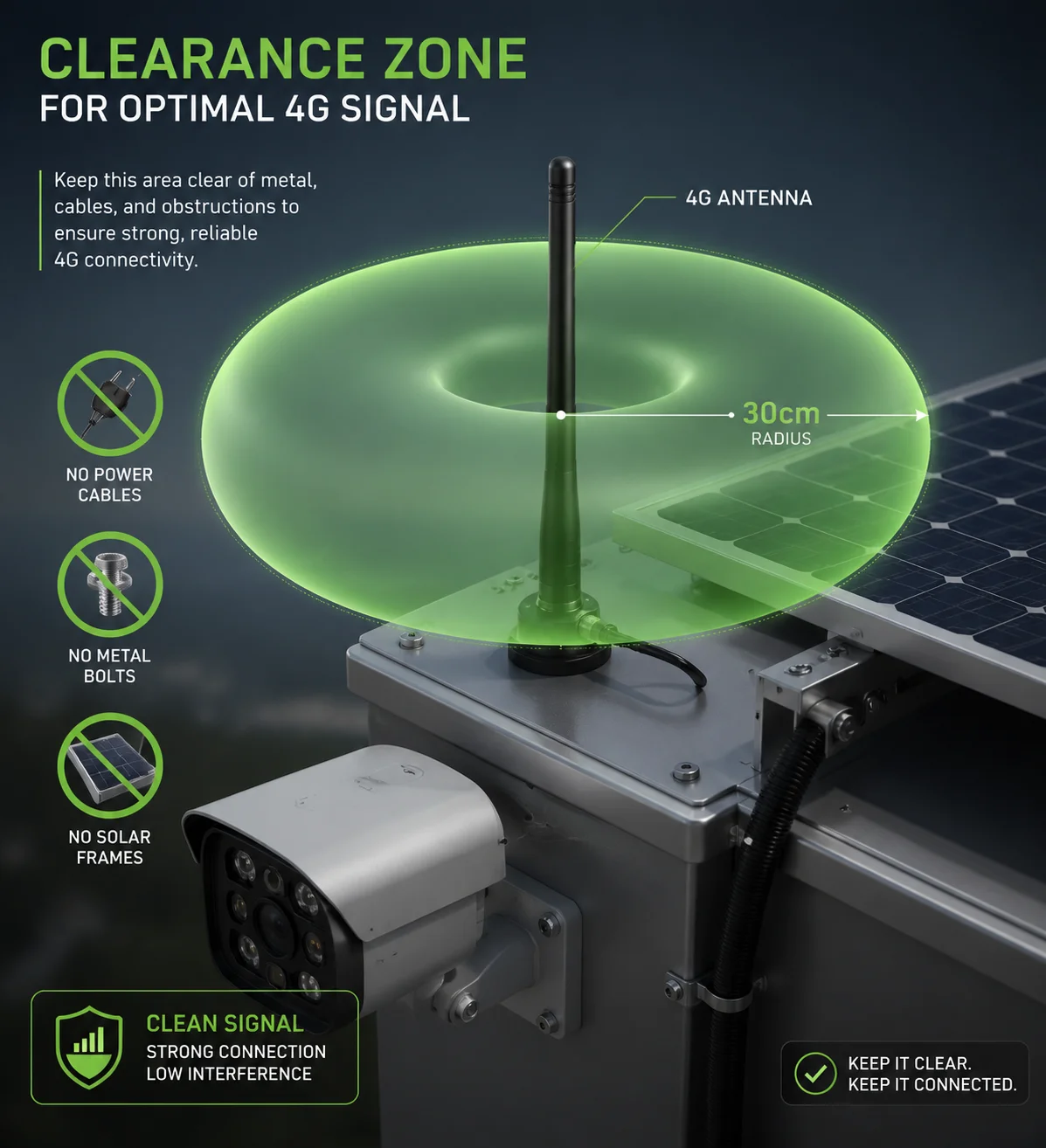 Clearance zone around 4G antenna on solar panel pole mount
Why a Clearance Zone Exists
An antenna does not just receive signals from its tip. It has a radiation pattern — a three-dimensional shape around it where it sends and receives radio waves. For a standard omnidirectional whip antenna (the kind used on most 4G solar cameras), this pattern looks like a donut. The signal is strongest in the horizontal plane and weakest directly above and below.
If you place a metal bracket inside this donut-shaped zone, it distorts the pattern. The antenna can no longer receive signals evenly from all directions. Some angles get blocked. Others get amplified by reflections. The result is an unpredictable, unstable connection.
The Clearance Zone Table
Here is a simple guide based on the frequency bands commonly used in North America:
| Frequency Band | Clearance from Metal (Minimum) | Clearance from Metal (Recommended) |
|---|---|---|
| 700 MHz (B12, B13, B14) | 30 cm | 40–45 cm |
| 850 MHz (B5) | 25 cm | 35 cm |
| 1700–1900 MHz (B2, B4, B66) | 15 cm | 25–30 cm |
| 2500 MHz (B41) | 10 cm | 20 cm |
These numbers are based on the one-wavelength rule I mentioned earlier, with some extra margin added for real-world conditions.
Do Not Forget About Cables
I see this mistake often. The installer keeps the antenna far from the bracket, but then runs a thick bundle of power cables right next to the antenna. Metal conductors — including copper wires inside cables — can also interfere with the antenna pattern. Keep power cables at least 10 cm away from the antenna. If you must cross a cable near the antenna, cross it at a 90-degree angle. Do not run cables parallel to the antenna.
EMI from the Charge Controller
There is another source of interference that most people overlook: the MPPT solar charge controller5. Some low-cost controllers use high-frequency switching circuits that generate electromagnetic noise. This noise can raise the “noise floor” around the antenna, making it harder for the 4G modem to pick up weak signals.
At Loyalty-Secu, our charge controllers use full metal shielding enclosures. The PCB layout is tested for RF compatibility. We make sure that during peak charging hours — usually around noon when the solar panel is producing maximum power — the controller does not create noise that interferes with the 4G module. This is a detail that most factories skip, but it matters a lot in the field.
Can the Antennas Be Relocated to the Top of the Solar Panel for Better Line-of-Sight?
I had a client in Alberta, Canada, ask me this exact question. His pole was only 3 meters tall, and the solar panel took up most of the top section. He wanted to mount the antenna right on the panel frame.
Yes, you can relocate the antennas to the top of the solar panel — and in many cases, you should. Mounting the antenna at the highest point gives it the best line-of-sight to cell towers. But you must use a proper extension bracket and low-loss coaxial cable to avoid signal loss.
 Antenna relocated to top of solar panel for better 4G line of sight
Why Top-Mounting Works Best
The higher the antenna, the fewer obstacles between it and the cell tower. Trees, buildings, terrain — all of these block or weaken 4G signals. By placing the antenna at the very top of the entire assembly, you give it the best possible chance of reaching the tower.
In rural deployments — farms, construction sites, oil fields — the nearest cell tower might be 5 to 15 km away. At that distance, every decibel of signal matters. Raising the antenna by just 30 cm can improve signal strength by 3–6 dB. That might not sound like much, but in practice, it can be the difference between a stable 1080p stream and a connection that drops every 10 minutes.
How to Do It Right
You cannot just tape the antenna to the top of the panel. Here is the correct method:
- Use an L-shaped stainless steel bracket6. Bolt it to the top of the pole or the panel frame. The bracket should hold the antenna vertically, pointing straight up.
- Use a pigtail extension cable. This is a short coaxial cable (usually 30–50 cm) with SMA connectors on both ends. It connects the 4G modem inside the camera housing to the external antenna on the bracket.
- Choose low-loss cable. If the cable run is longer than 50 cm, use LMR-200 or better. Standard RG-174 cable loses too much signal over distance. For a 1-meter run at 1800 MHz, RG-174 loses about 1.2 dB, while LMR-200 loses only 0.6 dB. That difference adds up.
- Waterproof the connectors. Use self-amalgamating tape7 or silicone sealant on every connector joint. Water inside a coaxial connector will destroy signal quality within weeks.
Watch Out for PTZ Camera Field of View
There is one more thing to check when you mount the antenna on top. If you are using a PTZ camera, make sure the antenna does not appear in the camera’s field of view when the camera tilts up or rotates.
I have seen installations where the camera pans to a certain angle and the antenna shows up right in the middle of the frame. Worse, at night, if the camera has IR or laser illumination, the light bounces off the antenna and creates a bright white spot on the image. The client thinks the camera is broken. It is not. It is just seeing its own antenna.
Before you finalize the installation, rotate the PTZ to every extreme position — full left, full right, full up, full down. Check the live feed. Make sure no part of the bracket, panel, or antenna enters the frame. Do this in the lab or on the ground before you raise the pole. It saves a lot of time.
A Note on Wind Load
One more practical concern: wind. When you add a bracket and antenna to the top of the panel, you increase the wind load8 on the pole. In areas with strong winds — like the Texas panhandle or the Canadian prairies — this matters. Make sure your pole and mounting hardware are rated for the local wind speed. A snapped bracket in a storm means a lost antenna and a dead system until someone drives out to fix it.
At Loyalty-Secu, we design our solar PTZ mounting kits to handle wind speeds up to 120 km/h. The antenna bracket is part of the kit, pre-drilled and ready to install. No guesswork needed.
Conclusion
Bracket layout directly affects your 4G signal. Keep antennas high, keep them away from metal, and always test before you raise the pole. Small details here prevent big problems later.
1. Explore considerations for off-grid camera systems including solar and cellular connectivity. ↩︎ 2. Reference table of 4G frequency bands used in North America and their corresponding wavelengths. ↩︎ 3. Learn about pigtail extension cables and how they help relocate antennas away from interference. ↩︎ 4. Learn how directional antennas can improve signal quality by focusing on one tower and rejecting reflections. ↩︎ 5. Find out how MPPT charge controllers work and why RF shielding matters for 4G systems. ↩︎ 6. See examples of L-shaped brackets designed for mounting antennas above solar panels. ↩︎ 7. Find out how to waterproof coaxial connectors using self-amalgamating tape. ↩︎ 8. Calculate wind loads on pole-mounted equipment to ensure structural safety. ↩︎