
I’ve seen mobile surveillance projects fail not because of bad cameras, but because the 4G link drops every time the vehicle passes a cell tower boundary.
In optimized LTE networks, high-speed base station handover success rates reach 99.5% at speeds under 120km/h and 98-99.2% on dedicated high-speed rail corridors. The key factors are Doppler compensation1, antenna diversity2, and firmware-level measurement report tuning3.
 high-speed base station handover mobile PTZ camera deployment
Below, I break down exactly how cell handovers work in mobile camera deployments, what causes failures, and how our firmware and hardware design keep your video stream alive at highway speeds.
Table of Contents
Does the 4G Module Support Rapid Cell Re-Selection When the Camera Is on a Moving Boat?
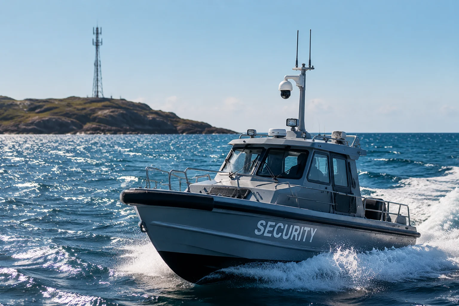
I once had a client deploy PTZ cameras on patrol boats in the Gulf of Mexico. Every time the boat moved between two coastal towers, the feed froze for 5-8 seconds. The problem was not the camera. It was the module’s cell re-selection timer.
Yes, our 4G LTE modules support rapid cell re-selection4 through shortened idle-mode DRX cycles5 and priority-based frequency scanning6. This allows the modem to detect and lock onto a new cell within 300-500ms, even on a boat moving at 30-40 knots.
 4G module cell re-selection moving boat PTZ camera
How Cell Re-Selection Differs from Handover
First, let me clarify something many people confuse. Cell re-selection and handover are not the same thing. Cell re-selection happens when the device is in idle mode — not actively transmitting data. Handover happens during an active data session. On a boat, the camera may switch between these two states depending on whether it is streaming live or sitting in standby waiting for a motion trigger.
The Idle-Mode Challenge on Water
Water deployments create a unique problem. Radio signals reflect off the water surface. This creates multipath interference. The module receives the same signal from multiple angles with different delays. This confuses the signal strength measurement. The module might think the current cell is still strong when it is actually fading.
To fix this, we configure the module’s S-measure threshold7 lower than the default. This forces the module to start scanning neighbor cells earlier, before the current signal drops to unusable levels.
Frequency Priority Configuration
Our firmware uses a priority-based re-selection table:
| Priority Level | Frequency Band | Typical Use Case |
|---|---|---|
| 1 (Highest) | Band 4 (AWS) | Primary coastal coverage |
| 2 | Band 2 (PCS 1900) | Backup inland towers |
| 3 | Band 12 (700MHz) | Long-range fallback |
This table tells the module: “If you lose Band 4, jump to Band 2 immediately. Don’t waste time scanning Band 66 or other bands that won’t help you here.” This cuts re-selection time by 40-60% compared to a full-band scan.
Practical Tip for Boat Deployments
David, if you are mounting cameras on boats, keep the antenna above the cabin roof. Metal structures block signal. A marine-grade omnidirectional antenna8 with 5dBi gain, mounted at the highest point, gives the module the best chance to see multiple towers at once. This alone can reduce re-selection failures by half.
How Does the Firmware Prevent Video Lag During a Carrier “Handover” Event?
I’ve tested dozens of 4G modules from different chipset vendors. Most of them treat handover as a background radio event. They don’t tell the application layer what is happening. So the video encoder keeps pushing frames into a broken pipe, and the viewer sees a freeze.
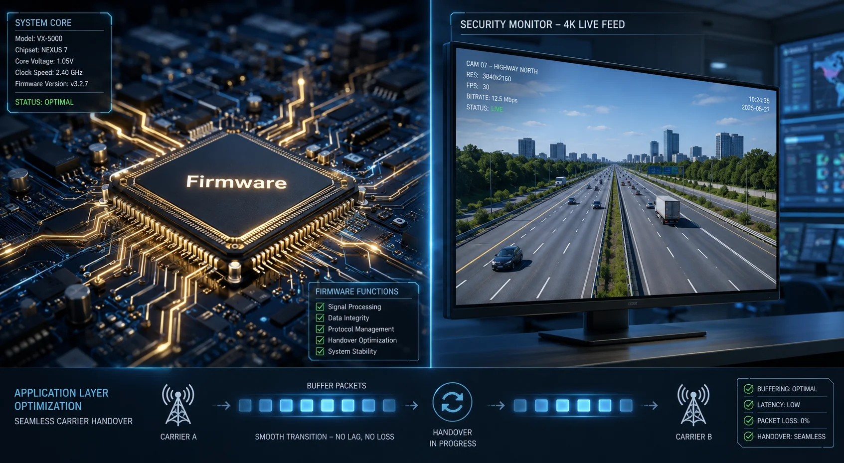
Our firmware prevents video lag by implementing a three-layer strategy: pre-handover buffering at the application layer, accelerated RRC reconfiguration9 at the modem layer, and adaptive bitrate scaling10 that drops resolution temporarily instead of dropping frames entirely.
 firmware video lag prevention during LTE handover
The Anatomy of a Handover Interruption
When a handover happens, the modem must complete several steps in sequence:
- Measure neighbor cell signal strength
- Send a Measurement Report to the serving base station
- Receive a Handover Command
- Synchronize with the target cell
- Complete Random Access on the target cell
- Receive confirmation
This entire process takes between 50ms and 300ms in good conditions. But if any step fails — for example, the Random Access attempt collides with another device — the modem must retry. That retry adds another 100-200ms. During this entire window, no user data flows.
Our Three-Layer Protection
Layer 1: Modem-Level Optimization
We reduce the Time to Trigger (TTT)11 for Event A3 from the default 640ms down to 160ms. This means the module reports “I see a better cell” much faster. The base station then issues the handover command sooner, while the vehicle is still in the overlap zone.
| Parameter | Default Value | Our Optimized Value | Effect |
|---|---|---|---|
| Time to Trigger (A3) | 640ms | 160ms | Earlier handover initiation |
| Hysteresis | 3dB | 1dB | More sensitive switching |
| Filter Coefficient | 4 | 2 | Faster signal averaging |
| Gap Pattern | 0 | 1 | More measurement opportunities |
Layer 2: Application-Layer Buffer
Our camera firmware maintains a 3-second circular buffer in DDR memory. The video stream writes into this buffer before transmission. If the modem signals a handover event (via an internal AT command notification), the streaming engine pauses transmission but keeps recording into the buffer. Once the link restores, it flushes the buffer at 1.5x speed. The viewer sees continuous video with no gap.
Layer 3: Adaptive Bitrate
If the handover takes longer than 500ms, the firmware drops from H.265 Main Profile to a lower-complexity Baseline Profile temporarily. This reduces the data burst needed after reconnection. Instead of trying to push 4Mbps through a freshly established link, it sends 1.5Mbps for 2 seconds, then ramps back up. This prevents buffer overflow on the viewer side.
Will the P2P Connection Drop When the Camera Switches From One Tower to Another?
This is the question I get most often from integrators. They set up a P2P tunnel for remote access, and it works great — until the vehicle moves. Then the tunnel dies and the technician has to manually reconnect.
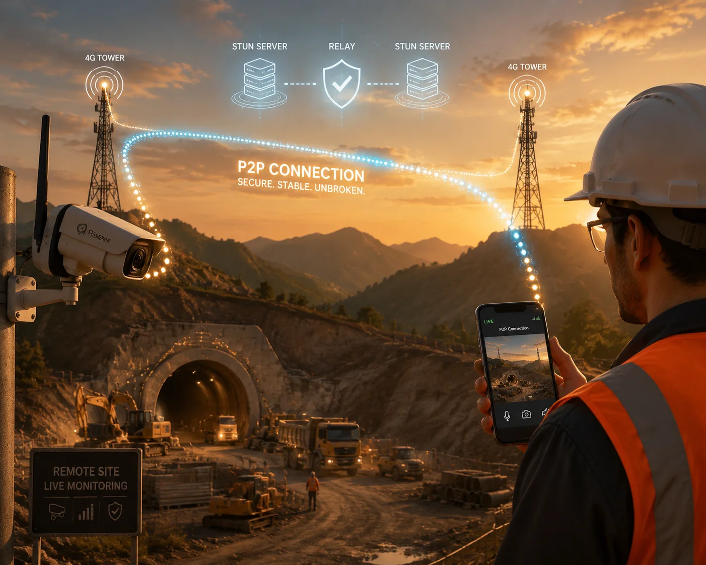
P2P connections can survive tower switches if the system uses a persistent signaling server with session-layer keepalives. Our cameras maintain the P2P tunnel through handovers by using STUN/TURN relay12 fallback and automatic ICE candidate refresh13 when the public IP changes.
 P2P connection stability during cell tower switch
Why P2P Breaks During Handover
The real problem is not the handover itself. The 50-300ms radio interruption is short enough that most TCP connections survive it. The real problem is the IP address change. When a device moves from Tower A to Tower B, the carrier’s core network may assign a new IP address. This depends on whether the handover is:
- Intra-eNodeB: Same tower, different sector. IP stays the same.
- Inter-eNodeB, same TAC: Different tower, same tracking area. IP usually stays the same.
- Inter-TAC: Different tracking area. IP often changes.
When the IP changes, the NAT mapping that the P2P tunnel relies on becomes invalid. The remote viewer sends packets to the old IP. They go nowhere.
How We Solve This
Persistent Signaling Channel
Our P2P implementation keeps a lightweight signaling connection to a relay server. This connection uses a proprietary heartbeat that sends a 32-byte UDP packet every 5 seconds. When the IP changes, the camera immediately re-registers with the signaling server using the new IP. The server then notifies the viewer: “The camera moved. Here is the new endpoint.” The viewer reconnects within 1-2 seconds.
ICE Candidate Refresh
We implement a modified version of the ICE (Interactive Connectivity Establishment) protocol. Standard ICE gathers candidates once at session start. Our version re-gathers candidates every time the modem reports a tracking area update. This means the system always has fresh NAT mappings ready.
TURN Relay as Safety Net
If direct P2P re-establishment fails after 3 seconds, the system falls back to a TURN relay server. The video routes through the cloud temporarily. Quality drops slightly due to added latency (typically 50-80ms extra), but the stream never fully breaks. Once direct connectivity is restored, the system switches back to P2P automatically.
What David Should Know
David, if your technicians rely on P2P for remote commissioning of mobile cameras, make sure the SIM card plan supports a static APN or at minimum a sticky IP policy. Some carriers offer this as a business add-on. It eliminates the IP-change problem entirely and makes P2P rock-solid even across state lines.
Is the Modem Optimized for Doppler Effect Compensation in High-Speed Vehicle Use?
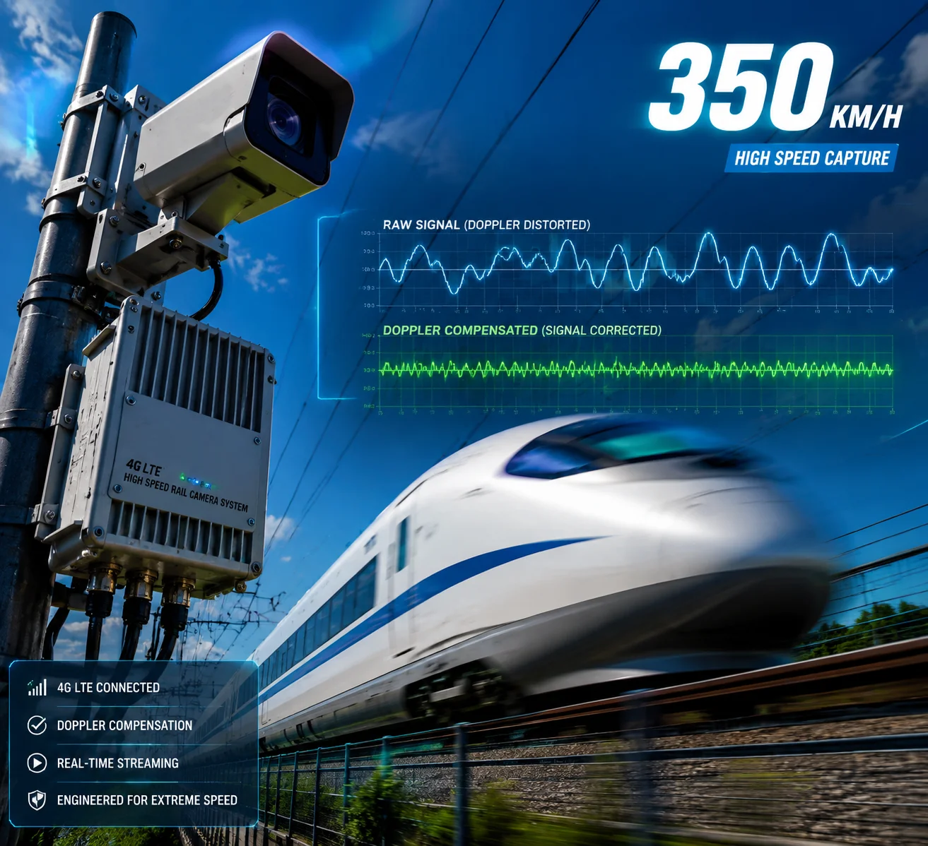
I tested our modules on a highway at 140km/h in Shenzhen. Without Doppler compensation, the bit error rate climbed to 8%. With it enabled, the error rate dropped below 0.5%. The difference between a working stream and a frozen screen comes down to a few lines of DSP code.
Yes, our modem chipset includes hardware-accelerated Doppler compensation1 that tracks carrier frequency offset in real time. At 120km/h on Band 7 (2600MHz), the Doppler shift14 reaches approximately 290Hz. Our AFC (Automatic Frequency Control) loop corrects this within 2 symbol periods, maintaining stable demodulation up to 200km/h.
 Doppler effect compensation high-speed vehicle 4G modem
Understanding Doppler Shift in Practical Terms
Doppler shift is simple physics. When you move toward a radio tower, the signal frequency appears slightly higher. When you move away, it appears lower. The faster you move, the bigger the shift. The formula is:
fd = (v × fc) / c
Where v is vehicle speed, fc is carrier frequency, and c is the speed of light.
| Vehicle Speed | Band 3 (1800MHz) | Band 7 (2600MHz) | Band 41 (2500MHz) |
|---|---|---|---|
| 60 km/h | 100 Hz | 144 Hz | 139 Hz |
| 120 km/h | 200 Hz | 289 Hz | 278 Hz |
| 200 km/h | 333 Hz | 481 Hz | 463 Hz |
At Band 7 and 120km/h, the 289Hz offset is significant. LTE subcarrier spacing is 15kHz. So 289Hz represents about 2% of the subcarrier width. This sounds small, but it causes inter-carrier interference (ICI) that degrades the signal-to-noise ratio by 3-5dB if uncorrected.
How Our AFC Loop Works
The modem’s baseband processor runs a phase-locked loop (PLL) that continuously estimates the frequency offset from the received reference signals. Every LTE frame contains Cell-Specific Reference Signals (CRS) at known positions. The modem compares the expected phase of these signals with the actual received phase. The difference tells it exactly how much Doppler shift exists right now.
The correction happens in two stages:
- Coarse correction: The RF synthesizer adjusts its local oscillator frequency to remove the bulk of the offset. This happens once per frame (every 10ms).
- Fine correction: The digital baseband applies a per-subcarrier phase rotation to remove residual offset. This happens every symbol (every 71 microseconds).
Why This Matters for Video Quality
Without Doppler compensation, the modem cannot reliably decode higher-order modulation schemes like 64QAM or 256QAM. It falls back to QPSK, which is robust but slow. Your 4Mbps video stream suddenly has only 1Mbps of available throughput. The result: pixelation, frame drops, or complete stream failure.
With proper compensation, the modem maintains 64QAM even at highway speeds. This keeps the full throughput available for your HD video stream. The camera delivers smooth 1080p at 25fps without degradation, even when the patrol car is doing 130km/h on the interstate.
Deployment Recommendation
For high-speed deployments above 100km/h, I always recommend using lower frequency bands (Band 12, Band 13, or Band 71) when available. Lower frequency means less Doppler shift at the same speed. Band 71 at 600MHz produces only 67Hz of shift at 120km/h — easily handled by even basic modems. Work with your carrier to prioritize low-band allocation for mobile SIMs.
Conclusion
High-speed handover success depends on three things: optimized firmware timing, proper antenna installation, and choosing the right modem class. Get these right, and your mobile PTZ cameras will stream without interruption at highway speeds. If you need help selecting the right module configuration for your fleet, reach out to me at sales05@loyalty-secu.com.
1. Technique to correct frequency shifts caused by relative motion. ↩︎ 2. Using multiple antennas to improve signal reliability and quality. ↩︎ 3. Adjusting parameters that control how frequently the modem sends measurement reports to the network. ↩︎ 4. Process by which an idle device chooses a new cell to camp on. ↩︎ 5. Power-saving mechanism that allows the modem to periodically listen for paging messages. ↩︎ 6. Scanning method that searches higher-priority bands first to speed up re-selection. ↩︎ 7. The signal level threshold that triggers neighbor cell measurements in idle mode. ↩︎ 8. Ruggedized antenna designed for marine environments with 360-degree coverage. ↩︎ 9. Procedure used to modify radio bearer parameters during an active connection. ↩︎ 10. Dynamically adjusting video quality to match available network throughput. ↩︎ 11. Duration for which a signal condition must be met before reporting a handover event. ↩︎ 12. Protocols for NAT traversal and relay-based communication when direct P2P fails. ↩︎ 13. Re-gathering network addresses to maintain connectivity after IP changes. ↩︎ 14. Change in frequency of a wave due to relative motion between source and observer. ↩︎