
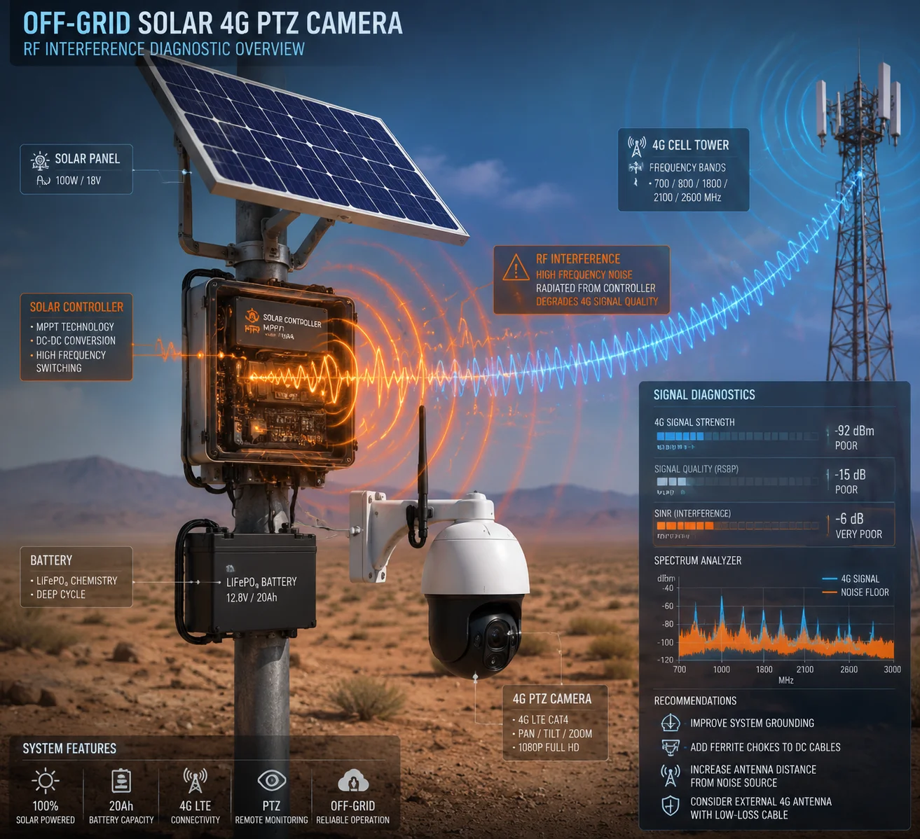
I’ve seen too many off-grid solar camera systems lose 4G signal in the field — not because of weak coverage, but because of their own power supply noise killing the receiver from the inside.
To prevent 4G module desense caused by solar controller ripple, you need to apply multi-stage power filtering, use shielded inductors, suppress common-mode noise on ground planes, and maintain physical separation between the switching power circuit and the 4G RF front end. These four measures together can reduce conducted and radiated EMI below the noise floor of the LTE receiver.
 Solar controller ripple and 4G module desense prevention
In this article, I will walk you through each critical area — from high-frequency filtering and EMI measurement to real-world signal degradation and shielding design. If you are building or sourcing solar-powered 4G surveillance systems for remote deployments, this is the engineering detail that separates a reliable product from a field failure. Let’s get into it.
Table of Contents
Does the Solar MPPT Controller Use High-Frequency Filtering to Protect the 4G Signal?
Most people think their MPPT controller1 output is “clean enough.” I thought so too — until I saw a 12 dB SINR drop on a perfectly good 4G link the moment the solar panel started charging at noon.
Yes, a well-designed solar MPPT controller must include dedicated high-frequency filtering on its output stage to protect the 4G signal. Without it, the switching harmonics from the MPPT converter will raise the noise floor of the LTE receiver, causing packet loss, reduced throughput, and even complete disconnection.
 MPPT controller high-frequency filtering for 4G protection
Why MPPT Switching Noise Is Dangerous to 4G
An MPPT controller works by rapidly switching current on and off. The switching frequency is usually between 100 kHz and 1 MHz. That sounds far away from 4G bands like B13 (746–756 MHz) or B71 (617–652 MHz). But here is the problem: the switching waveform is not a clean sine wave. It is a square wave. And square waves produce harmonics — integer multiples of the base frequency — that extend far into the RF spectrum.
For example, a controller switching at 500 kHz will produce harmonics at 1 MHz, 1.5 MHz, 2 MHz, and so on. By the time you reach the 700th harmonic, you are sitting right on top of the B13 LTE Band 1311. These harmonics are weak individually, but they add up. They create a broadband noise floor that the 4G module’s receiver cannot distinguish from real signal interference.
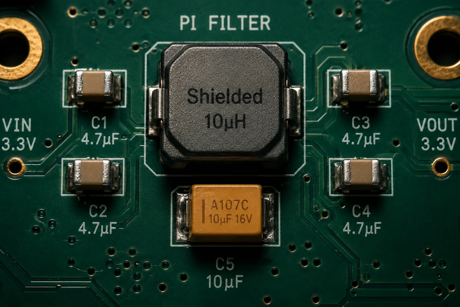
The Pi Filter Solution
The most effective hardware fix is a π (Pi filter2) placed between the MPPT output and the 4G module’s power input. A Pi filter uses two capacitors and one inductor arranged in a C-L-C configuration. It works like a dam — it blocks conducted noise from passing through the power rail.
Here is a basic component selection guide:
| Component | Recommended Value | Purpose |
|---|---|---|
| Input Capacitor (C1) | 100 µF polymer tantalum, low ESR | Absorb low-frequency ripple |
| Series Inductor (L1) | 10 µH ferrite-core choke | Block mid-to-high frequency noise |
| Output Capacitor (C2) | 10 µF MLCC + 100 nF MLCC + 10 pF MLCC in parallel | Shunt high-frequency harmonics to ground |
Why Multiple Capacitors Matter
A single large capacitor cannot filter all frequencies. A 100 µF capacitor is great at absorbing 100 kHz ripple, but it becomes almost useless above 10 MHz because of its own internal inductance (ESL (Equivalent Series Inductance)12). That is why you need to place smaller ceramic capacitors in parallel. The 100 nF cap handles the MHz range. The 10 pF cap catches noise up into the GHz range. Together, they form a broadband filter wall.
At Loyalty-Secu, we design our solar 4G PTZ systems with this multi-stage filtering built into the main board. We do not rely on the external solar controller alone to deliver clean power. We treat every power rail going to the 4G module as a potential noise source and filter it at the point of entry.
Shielded Inductors Are Non-Negotiable
The inductor inside the MPPT controller is the single biggest source of radiated EMI. If it uses an unshielded drum-core inductor, the magnetic field leaks out in all directions. This field can couple directly into the 4G antenna feed line or even into the RF traces on the PCB.
Always verify that the MPPT controller uses shielded inductors3, closed-magnetic-path inductors. These inductors contain the magnetic flux inside the component body. The difference in radiated emissions between a shielded and unshielded inductor can be 20 dB or more — that is the difference between a working 4G link and a dead one.
How Do You Measure the EMI Impact of the Solar Charging Circuit on the LTE Receiver?
I used to guess whether the solar controller was causing 4G problems. Then I started measuring. The data told a completely different story from what I assumed.
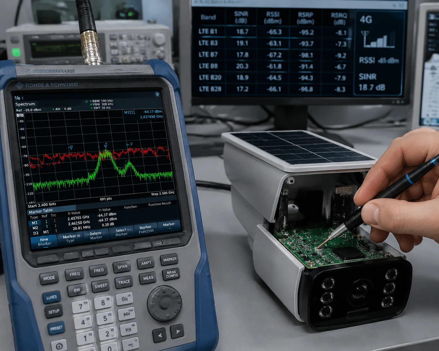
To measure the EMI impact, use a spectrum analyzer5 to compare the 4G module’s noise floor with the solar controller on and off. Monitor RSSI and SINR4 simultaneously. If RSSI stays the same but SINR drops significantly when charging begins, the solar controller is causing receiver desense through conducted or radiated interference.
 Measuring EMI impact of solar charging on LTE receiver
The Two-State Comparison Test
The simplest and most reliable test method is a two-state comparison. You need a spectrum analyzer (even a low-cost SDR-based one works for initial screening) and access to the 4G module’s diagnostic interface (AT commands or a management dashboard that reports RSSI, RSRP, RSRQ, and SINR).
Step 1: At night, when the solar panel is not charging, record the baseline values:
- RSSI (Received Signal Strength Indicator)
- SINR (Signal to Interference plus Noise Ratio)
- RSRP (Reference Signal Received Power)
Step 2: At solar noon, when the MPPT controller is running at full power, record the same values again.
Step 3: Compare the two data sets.
How to Interpret the Results
| Measurement | Night (No Charging) | Noon (Full Charging) | What It Means |
|---|---|---|---|
| RSSI | -75 dBm | -75 dBm | Signal strength unchanged — tower signal is stable |
| SINR | 18 dB | 6 dB | Noise floor raised by ~12 dB — desense confirmed |
| RSRP | -85 dBm | -85 dBm | Reference signal power unchanged |
| RSRQ | -8 dB | -16 dB | Signal quality degraded due to interference |
This pattern — stable RSSI but dropping SINR — is the classic fingerprint of self-generated interference. The 4G module is receiving the same amount of signal from the tower, but the noise inside the device has gone up. So the signal-to-noise ratio collapses.
Conducted vs. Radiated: Finding the Path
Once you confirm desense exists, you need to find out how the noise is getting into the 4G module. There are two paths:
Conducted path: Noise travels through the power supply wires from the controller to the module. You can test this by temporarily powering the 4G module from a clean bench supply (like a battery with no switching regulator). If SINR recovers, the conducted path is the main problem.
Radiated path: Noise radiates through the air from the controller’s inductor, PCB traces, or cables, and couples into the 4G antenna or RF traces. You can test this by keeping the noisy power supply connected but moving the solar controller physically far away (1 meter or more) with long extension wires. If SINR improves with distance, radiation is the dominant path.
In most real-world solar camera systems, both paths contribute. But conducted noise is usually easier and cheaper to fix with filters. Radiated noise requires shielding, layout changes, or physical separation.
Near-Field Probe Scanning
For a more advanced diagnosis, use a near-field EMI probe6 set connected to a spectrum analyzer. Move the probe slowly across the PCB surface while the MPPT controller is running. You will see the emission hotspots — usually the switching FET, the inductor, and the input/output traces of the converter. This tells you exactly where to add shielding or reroute traces.
At Loyalty-Secu, we perform this near-field scan during the R&D phase of every new solar PTZ design. We catch EMI problems before they reach production. This is one reason our systems maintain stable 4G connections even in weak signal areas like rural Texas ranches or remote Canadian pipeline sites.
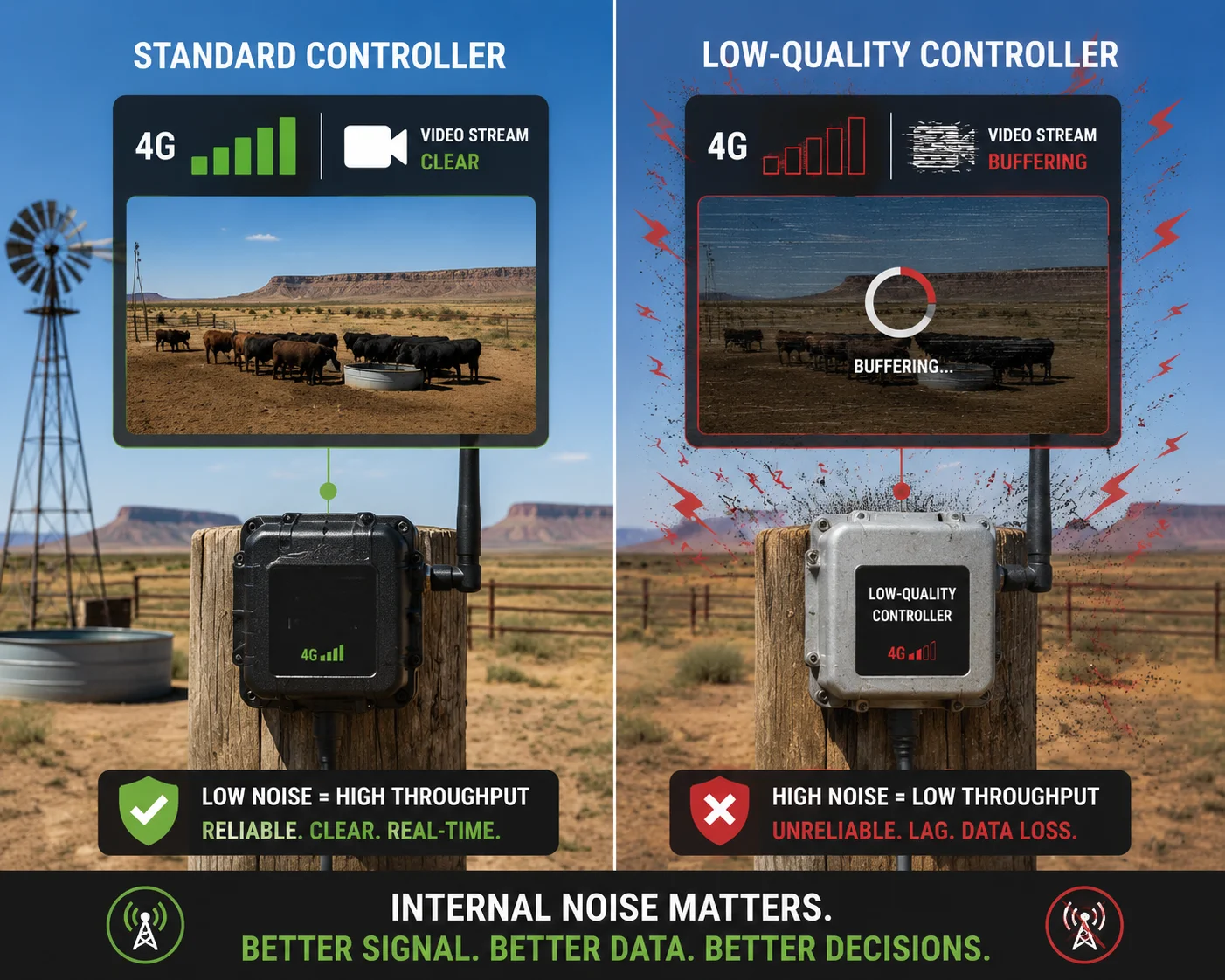
Will a Low-Quality Solar Controller Reduce My 4G Upload Speed in Weak Signal Areas?
I had a customer in West Texas — let’s call him David — who reported that his solar cameras worked fine in the morning and evening but dropped to unusable upload speeds every day between 11 AM and 3 PM. The cellular tower had not changed. The signal bars looked the same. But the data would not move.
Yes, a low-quality solar controller will absolutely reduce your 4G upload speed, especially in weak signal areas. The switching noise from a cheap controller raises the receiver noise floor, which directly reduces SINR. In strong signal areas, the module can tolerate this. In weak signal areas, even a small increase in noise pushes the link below the minimum SINR threshold for higher modulation schemes, forcing the modem to fall back to slower data rates or disconnect entirely.
 Low-quality solar controller reducing 4G upload speed
The SINR-Throughput Relationship
To understand why this happens, you need to know how 4G LTE adapts to signal conditions. The base station and the module negotiate a modulation and coding scheme (MCS) based on the current SINR. Higher SINR allows more complex modulation, which means faster data rates.
| SINR Range | Typical Modulation | Approximate Upload Speed |
|---|---|---|
| > 20 dB | 64QAM | 10–15 Mbps |
| 13–20 dB | 16QAM | 5–10 Mbps |
| 5–13 dB | QPSK | 1–5 Mbps |
| < 5 dB | QPSK (low rate) or disconnect | < 1 Mbps or no service |
Now imagine your site has a baseline SINR of 10 dB — already in the “weak but workable” zone. A cheap solar controller adds 6 dB of noise floor. Your effective SINR drops to 4 dB. The module falls from QPSK at a reasonable rate down to the edge of connectivity. Video upload stalls. Alarms fail to send. The system becomes unreliable exactly when it should be working hardest — during daylight hours when solar charging is active and the camera is most needed.
What Makes a Controller “Low Quality” in RF Terms
Price alone does not tell you if a controller will cause desense. Here are the specific design shortcuts that cheap controllers take:
Unshielded inductors. This is the number one problem. Open-core or semi-shielded inductors radiate magnetic fields that couple into nearby RF circuits. A good controller uses fully shielded, molded inductors with closed magnetic paths.
No input/output filtering. Budget controllers often skip the output filter capacitors or use only a single electrolytic cap. Electrolytic capacitors have high ESR and high ESL — they are almost useless above 1 MHz. Without ceramic decoupling caps, all the high-frequency switching noise passes straight through to the load.
Poor PCB layout. Wide current loops on the PCB act like loop antennas. A well-designed controller minimizes the area of the switching current loop by placing the input capacitor, FET, and inductor as close together as possible. Cheap boards spread these components out, maximizing radiated emissions.
No spread spectrum. Higher-end MPPT controllers use spread-spectrum frequency modulation7. Instead of switching at a fixed 500 kHz, the frequency wobbles between, say, 450 kHz and 550 kHz. This spreads the harmonic energy across a wider bandwidth, reducing the peak interference at any single frequency. Cheap controllers switch at a fixed frequency, concentrating all the harmonic energy into narrow spikes that can land directly on an LTE channel.
The Real Cost of Saving $5 on a Controller
David’s situation is common. He saved $5 per unit by using a generic MPPT controller from an unvetted supplier. But each truck roll to a remote camera site costs him $300–$500 in labor and fuel. After three site visits trying to diagnose “network problems” that were actually self-interference, he had spent more on troubleshooting than the entire camera system cost.
When we redesigned his system with our integrated solar PTZ platform — which includes a properly filtered and shielded MPPT stage — his noon-hour upload speeds recovered from under 1 Mbps to a consistent 4–6 Mbps. No more truck rolls. No more angry end-customer calls.
This is why I always tell B2B buyers: the solar controller is not just a power component. It is an RF component. Treat it that way.
Is There a Dedicated Shielding Layer Between the Power Board and the 4G Antenna?
When I first started designing solar 4G camera systems, I thought keeping the power board and the 4G antenna on opposite sides of the enclosure was enough. It was not. The noise found its way through the ground plane12, through the cables, and through every gap in the housing.
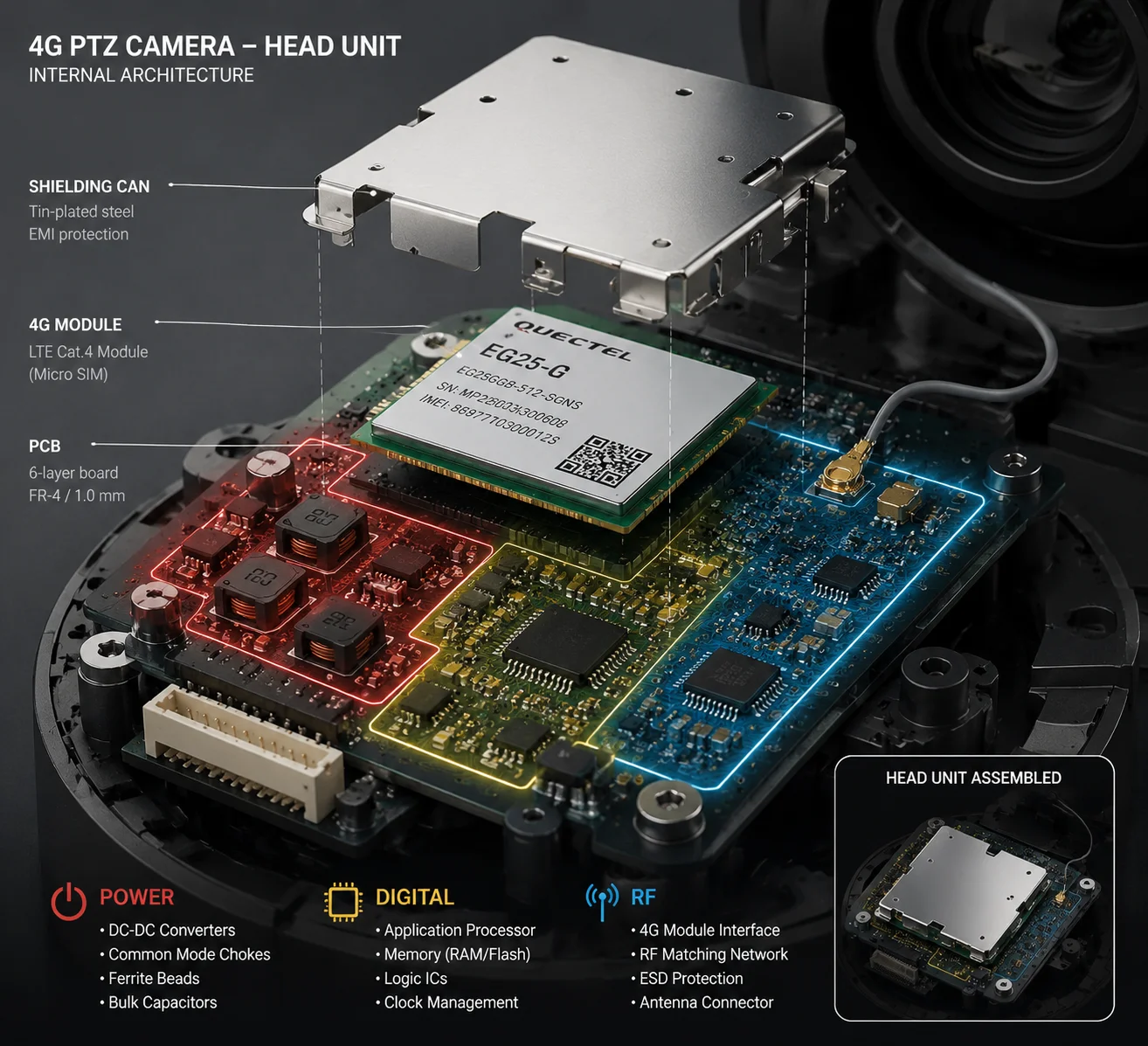
Yes, a properly engineered solar 4G surveillance system must include a dedicated shielding layer — typically a metal partition or shielding can — between the power conversion board and the 4G antenna and RF front end. This shielding creates a Faraday cage effect that blocks radiated EMI from the switching circuits, preventing it from coupling into the sensitive LTE receiver chain.
 Shielding layer between power board and 4G antenna
Why Physical Distance Alone Is Not Enough
Many engineers assume that placing the 4G antenna 5 cm or more away from the power board solves the radiation problem. In an open-air lab bench test, this might work. But inside a sealed camera housing — especially a metal or semi-metal enclosure — the situation is very different.
Metal enclosures create reflections. EMI bounces off the walls and can actually concentrate in unexpected spots. Cables act as waveguides, carrying noise from one end of the enclosure to the other. The power supply cable to the 4G module is especially dangerous because it runs from the noisy power board directly to the sensitive RF module, acting as both a conducted and radiated noise path.
The Shielding Can Approach
The most effective solution is a metal shielding can10 soldered directly over the 4G module on the PCB. This is standard practice in smartphone design, and it works equally well in industrial camera systems.
The shielding can must meet these requirements:
- Material: Tin-plated steel or mu-metal for magnetic shielding.
- Grounding: Multiple solder points connecting the can to the PCB ground plane. A single ground point is not enough — it creates a slot antenna at high frequencies.
- Seam integrity: No gaps or slots longer than 1/20th of the wavelength at the highest frequency of concern. For 700 MHz LTE, that means no gaps longer than about 21 mm.
Board-Level Partitioning
Beyond the shielding can, the PCB itself should be designed with clear zone separation:
Power zone: Contains the MPPT converter, battery charging circuit, and voltage regulators. This zone has its own ground pour connected to the main ground plane through a controlled number of vias.
RF zone: Contains the 4G module, SIM card holder, antenna matching network, and antenna connector. This zone has a solid, unbroken ground plane12 underneath. No power traces or switching signals should cross this zone.
Digital zone: Contains the main processor, video encoder, and memory. This zone sits between the power and RF zones and acts as a buffer.
Common Mode Chokes on Every Cable
Every cable that crosses from the power zone to the RF zone is a potential noise carrier. This includes:
- The DC power cable to the 4G module
- The USB or UART data lines between the processor and the 4G module
- The SIM card signal lines
Each of these should pass through a common mode choke9. A common mode choke is a special type of inductor wound on a single core with two windings in opposite directions. Normal differential signals pass through without loss. But common mode noise — the kind that turns cables into antennas — gets absorbed.
Ferrite Beads as a Last Line of Defense
In addition to common mode chokes, place ferrite bead8s on the power input pin of the 4G module. A ferrite bead acts as a frequency-dependent resistor. At low frequencies (DC to a few MHz), it has almost zero resistance. At high frequencies (100 MHz and above), it presents significant impedance, converting RF noise into heat.
Choose ferrite beads with high impedance at the frequencies that matter. For LTE Band 1311 (around 750 MHz), select a bead with peak impedance near that frequency. Murata and TDK both publish impedance-vs-frequency curves for their ferrite bead product lines — use these curves to make the right selection.
Our Approach at Loyalty-Secu
In our 4G solar PTZ camera systems, we implement all four layers of protection:
- A metal shielding can over the 4G module with 8-point ground soldering.
- Board-level zone separation with dedicated ground planes.
- Common mode chokes on all inter-zone cables.
- Ferrite beads on power and signal lines entering the RF zone.
We also run a full EMC pre-compliance scan13 on every new design before sending it to a certified lab. This catches problems early and saves weeks of redesign time. For our B2B customers like David, this means the product works on day one — no field debugging, no truck rolls, no lost contracts.
Conclusion
Controlling solar controller ripple to prevent 4G desense requires multi-stage filtering, shielded inductors, proper grounding, and physical RF isolation — all designed in from the start, not patched in the field.
1. Learn how MPPT controllers maximize solar panel efficiency and why their switching noise can interfere with 4G. ↩︎ 2. Understand how a Pi filter (C-L-C) blocks conducted noise from switching power supplies. ↩︎ 3. See why closed-magnetic-path inductors are essential to reduce radiated EMI from switching converters. ↩︎ 4. Signal to Interference plus Noise Ratio is the key metric for LTE performance and desense detection. ↩︎ 5. Use a spectrum analyzer to measure the noise floor and identify conducted/radiated interference. ↩︎ 6. Near-field probes help locate emission hotspots on a PCB for targeted shielding. ↩︎ 7. Spread-spectrum reduces peak interference by varying the switching frequency over a range. ↩︎ 8. Ferrite beads provide frequency-dependent impedance to absorb high-frequency noise on power lines. ↩︎ 9. Common mode chokes suppress noise that appears on both signal lines relative to ground. ↩︎ 10. A metal shielding can creates a Faraday cage to block radiated EMI from the 4G module. ↩︎ 11. Band 13 (746–756 MHz) is commonly used in North America and can be susceptible to harmonic interference. ↩︎ 12. A solid ground plane reduces ground loops and provides a low-impedance return path for RF currents. ↩︎ 13. Pre-compliance EMC testing catches radiated/conducted emissions issues early in the design cycle. ↩︎