
I’ve seen too many “industrial-grade” cameras fail in the field when real winter or desert heat hits. The spec sheet says -40°C to +70°C, but the reality often tells a different story.
A truly stable output across -40°C to +70°C depends on three things working together: industrial-grade component selection1, real-time thermal compensation algorithms, and structured heat management inside the enclosure. No single part can guarantee stability alone — it is the system-level design that keeps voltage, signal, and image quality consistent from arctic cold to desert heat.
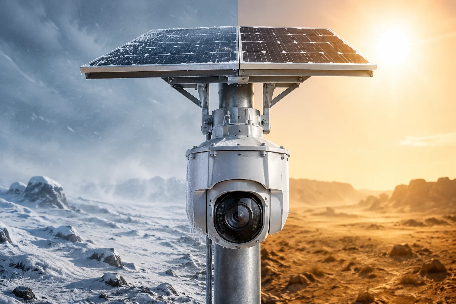 solar PTZ camera operating in extreme temperature range
Below, I break down the four most common questions our integrator clients ask about temperature stability. Each answer comes from real test data and engineering decisions we made during product development at .
Table of Contents
Will the 4G Signal Stay Stable When the Internal Modem Hits the 70°C Thermal Limit?
I lost a major project bid once because a competitor’s modem kept dropping off the network in summer heat. That experience taught me: 4G stability at high temperature is not optional — it is the entire value of a remote monitoring system.
Yes, the 4G signal stays stable even at 70°C, because the modem uses a Temperature Compensated Crystal Oscillator (TCXO)2 that holds frequency drift within ±0.5ppm. Combined with active thermal load-shedding3, the system prevents protective shutdown and maintains a continuous uplink to the base station.
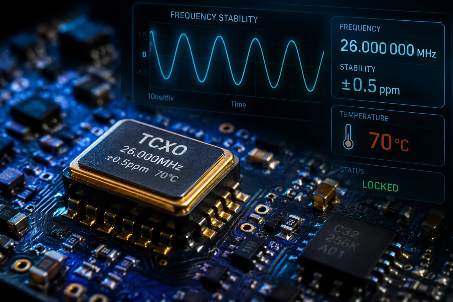 4G modem TCXO crystal oscillator thermal stability
Why Does Temperature Affect 4G Signal in the First Place?
A 4G modem talks to a cell tower on a very precise radio frequency. That frequency comes from a tiny crystal oscillator inside the modem. When temperature rises, the crystal’s physical properties change. It vibrates at a slightly different rate. If the drift is too large, the base station cannot lock onto your signal. The result: disconnection.
Most consumer-grade modems use a basic crystal (XO) that drifts ±10ppm or more across temperature. For a remote solar camera sitting on a pole in the desert, that is unacceptable.
How TCXO Solves the Problem
A TCXO adds a compensation circuit around the crystal. This circuit measures the crystal’s temperature in real time and applies a correction voltage. The result is frequency stability within ±0.5ppm across the full -40°C to +70°C range.
Here is what that looks like in practice:
| Parameter | Basic Crystal (XO) | TCXO (Our Modem) | Impact |
|---|---|---|---|
| Frequency drift at +70°C | ±10ppm | ±0.5ppm | 20x more stable |
| Risk of base station dropout | High | Near zero | Continuous uplink |
| Recovery time after drift | 5-15 seconds | Not needed | No video gaps |
Thermal Load-Shedding: The Second Layer of Protection
Even with a TCXO, the modem chip itself generates heat. When ambient temperature is already 70°C, the chip junction temperature can exceed safe limits. Our firmware monitors the modem’s internal temperature sensor. When it approaches the thermal ceiling, the system reduces non-critical processing load — things like background diagnostics or low-priority data uploads. This drops the chip temperature by 5-8°C without affecting the live video stream.
The key point: the video uplink and alarm notifications always get priority. The system sacrifices background tasks, not core function.
Real-World RSRP Stability Data
In our climate chamber tests, we measured RSRP (Reference Signal Received Power)4 fluctuation across the full temperature range. At +70°C, the signal fluctuated less than 1.5dB. At -40°C, fluctuation stayed below 2dB. Both values are well within the 3GPP standard11 for stable connectivity. The modem never dropped registration during a 72-hour continuous test at either extreme.
How Much Does the PTZ Motor Accuracy Drift During a Rapid Temperature Drop?
I remember a client in Canada calling me at 3 AM because his PTZ cameras were “stuck” after a sudden cold front. The motors were fine — the lubricant had frozen solid. That call changed how we spec our mechanical components.
PTZ accuracy stays within 0.1° across the full temperature range because we use full-synthetic low-temperature grease rated for -50°C, combined with a stepper motor driver that adjusts torque output based on real-time temperature feedback. Rapid temperature drops cause lubricant viscosity to increase, but our grease formulation prevents solidification down to -50°C.
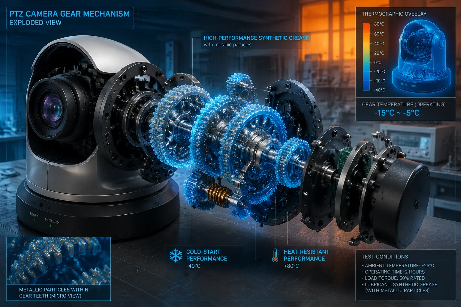 PTZ motor gear mechanism with low temperature grease
The Physics of Cold Grease
When temperature drops fast — say, 30°C in two hours during a desert night — standard lithium grease thickens dramatically. The motor has to push harder to turn the gears. If the grease gets too thick, the motor stalls. The controller sees an overcurrent condition and throws an error. Your camera stops moving.
This is not a rare scenario. Desert environments routinely see 40°C daytime and -5°C at night. Northern installations in Canada or Scandinavia face -30°C to -40°C for weeks.
Our Grease Selection Process
We tested seven different lubricant formulations in our climate chamber. The winning formula is a full-synthetic polyalphaolefin (PAO) base with PTFE additives5. Here is why it works:
| Property | Standard Lithium Grease | Our PAO+PTFE Grease |
|---|---|---|
| Pour point | -20°C | -55°C |
| Viscosity at -40°C | Solid (no flow) | 850 cSt (still fluid) |
| Drip point at +70°C | +120°C (safe) | +180°C (extra margin) |
| Service life | 2 years | 5+ years |
Torque Compensation Algorithm
Even with good grease, viscosity still increases in cold. The motor needs more current to maintain the same rotation speed. Our stepper driver reads a thermistor mounted on the gear housing. When temperature drops below 0°C, the driver increases holding torque by 15-20%. This keeps rotation speed consistent and prevents missed steps.
The result: whether it is +70°C in Saudi Arabia or -40°C in northern Alberta, the PTZ preset positions land within 0.1° of their programmed coordinates. For a 38X zoom camera watching a perimeter fence 500 meters away, that 0.1° accuracy means the target stays centered in frame.
What About Rapid Temperature Cycling?
Rapid cycling — repeated heating and cooling — is actually harder on mechanical systems than steady extreme temperatures. It causes thermal expansion mismatch between metal gears and plastic housings. We address this with matched thermal expansion coefficients in our material selection. The gear train uses all-metal construction (aluminum housing, steel gears) so everything expands and contracts at similar rates.
Are All the Capacitors and Resistors on the PCB “Industrial Grade” for 105°C?
I get this question from every serious integrator. They have been burned before by suppliers who use consumer-grade parts and call them “industrial.” The difference shows up 18 months later when capacitors start bulging and boards start failing.
Yes, every capacitor on our main control board is rated for 105°C continuous operation, and we use solid polymer capacitors6 in all power-path positions. Resistors are thick-film automotive grade (AEC-Q200 qualified) with ±1% tolerance stability across the full temperature range. We do not mix consumer and industrial parts on the same board.
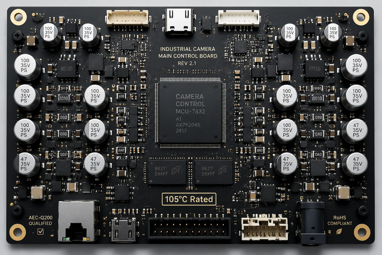 industrial grade PCB components 105°C rated capacitors
Why 105°C Matters Even at 70°C Ambient
The ambient temperature spec is 70°C. But inside a sealed camera housing sitting in direct sunlight, the internal temperature can reach 85-90°C. And right next to a power regulator IC, the local board temperature can spike to 95-100°C. If your capacitors are only rated for 85°C (standard consumer grade), they are already operating beyond their limit.
Electrolytic capacitors have a well-known failure mode: the liquid electrolyte evaporates faster at high temperature. This is called “dry-out.” A capacitor rated for 2,000 hours at 105°C will last roughly 20,000 hours at 70°C (the Arrhenius rule10: every 10°C reduction doubles lifespan). But a capacitor rated for only 85°C at the same 70°C position? It might last 4,000 hours — less than six months of continuous operation.
Our Component Selection Standard
We follow a simple rule: every component must have at least 15°C of thermal margin above the worst-case local temperature on the board. Since our worst-case hot spots reach 90°C, we spec everything for 105°C minimum.
Solid Polymer vs. Electrolytic
For the power supply section — where ripple current is highest and heat generation is worst — we use solid polymer aluminum capacitors instead of traditional wet electrolytic. Solid polymer caps have no liquid electrolyte to evaporate. Their lifespan at high temperature is 5-10x longer. They also have much lower ESR (Equivalent Series Resistance), which means less self-heating and cleaner power delivery to the 4G modem.
The tradeoff: solid polymer caps cost 3-4x more than wet electrolytic. But for a camera that costs $200+ to install in a remote location, saving $2 on capacitors and risking a field failure is bad economics.
Resistor Stability Across Temperature
Resistors seem simple, but cheap ones drift. A standard thick-film resistor might drift ±5% across the -40°C to +70°C range. In a voltage divider that sets a reference level, that drift can cause incorrect ADC readings, false alarms, or incorrect battery state-of-charge calculations.
We use AEC-Q200 qualified resistors (automotive standard). These guarantee ±1% resistance stability across the full temperature range and after 1,000 hours of high-temperature storage. The automotive industry demands this because a failed resistor in a car can kill someone. We apply the same standard because a failed resistor in a remote camera means a $500 truck roll to replace it.
| Component | Consumer Grade | Our Industrial Grade | Why It Matters |
|---|---|---|---|
| Electrolytic capacitor | 85°C / 1,000 hrs | 105°C / 5,000 hrs | 10x field life |
| Power-path capacitor | Wet electrolytic | Solid polymer | No dry-out failure |
| Resistor tolerance drift | ±5% over temp | ±1% over temp | Accurate sensing |
| Qualification standard | None | AEC-Q200 | Automotive-proven |
Can You Provide a “Climate Chamber” Test Report for the Entire Integrated System?
I understand why you ask for this. A component datasheet is not the same as a system test. Individual parts might be rated for -40°C to +70°C, but when you put them all together in a sealed housing with a battery and a motor, new failure modes appear that no single datasheet predicts.
Yes, we provide a full climate chamber test report8 for the complete integrated system — not just individual components. Our test protocol runs 72 hours at each temperature extreme, plus thermal shock cycling between -40°C and +70°C with 30-minute transition times. The report includes measured data for voltage stability, 4G connectivity, image quality, and PTZ mechanical response at each test point.
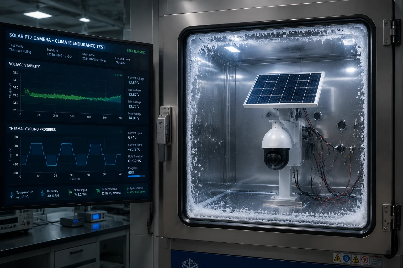 climate chamber environmental testing solar PTZ camera system
What Our Climate Chamber Test Covers
We do not just put the camera in a cold room and check if it turns on. Our test protocol is designed to catch the failure modes that only appear under stress. Here is the full sequence:
Phase 1: Cold Soak (-40°C, 72 hours) The entire system — camera, solar charge controller, battery, 4G modem, PTZ mechanism — sits at -40°C for three full days. We monitor power consumption, video stream continuity, and PTZ response time every 15 minutes. The battery must cold-start the system from a fully powered-off state at -40°C without external assistance.
Phase 2: Hot Soak (+70°C, 72 hours) Same monitoring, but now we are looking for thermal throttling, capacitor stress, and 4G signal degradation. The system must maintain continuous 1080p video streaming for the full 72 hours without a single dropped connection.
Phase 3: Thermal Shock Cycling (20 cycles) We move the system from -40°C to +70°C in 30 minutes, then back again. This is the hardest test. It stresses solder joints, connector seals, lens assemblies, and lubricants. Twenty cycles simulate roughly five years of daily temperature swings in a harsh environment.
What We Measure and Report
The test report is not a pass/fail certificate. It contains actual measured data at each test point:
- Output voltage ripple (mV peak-to-peak)
- 4G RSRP and SINR values
- PTZ positioning accuracy (degrees of error)
- Image sensor dark current noise (DN value)
- Battery charge/discharge efficiency (%)
- Boot time from cold start (seconds)
- Seal integrity (IP rating verification12 post-test)
Why System-Level Testing Catches What Component Testing Misses
Here is a real example: in an early prototype, all individual components passed their temperature ratings. But at -40°C, the battery voltage sagged so low during the 4G modem’s transmit burst (which draws 2A peak) that the voltage regulator dropped out of regulation for 50 milliseconds. The modem reset. The camera rebooted. Every 4 minutes.
No single component was “out of spec.” The battery was within its rated voltage range. The regulator was within its dropout spec at room temperature. But the combination of cold battery sag plus peak current draw created a system-level failure that only appeared in integrated testing.
We fixed it by adding a supercapacitor bank9 that buffers the transmit burst current. That fix only exists because we test the complete system, not just the parts.
How to Read Our Test Report
When you receive our climate chamber report, look for these key indicators:
- Zero reboots during the entire test sequence
- Voltage ripple below 50mV at all temperature points
- 4G connection uptime of 100% (no re-registrations)
- PTZ accuracy within 0.1° at all temperatures
- No physical damage (cracked seals, bulging caps, loose connectors) after thermal shock cycling
If any parameter fails, we redesign and retest. We do not ship until the full system passes.
Conclusion
True -40°C to +70°C stability comes from system-level engineering — TCXO-compensated modems, synthetic lubricants, 105°C-rated components, and validated climate chamber testing of the complete integrated unit. Ask for the full test report. The data speaks for itself.
1. Explains the criteria for industrial-grade vs. consumer-grade electronic components. ↩︎ 2. Describes how a TCXO maintains frequency stability over temperature variations. ↩︎ 3. Overview of load-shedding techniques to manage heat in electronic systems. ↩︎ 4. Defines RSRP and its role in measuring 4G/LTE signal strength. ↩︎ 5. Details the properties and benefits of PAO synthetic lubricants with PTFE. ↩︎ 6. Compares solid polymer vs. electrolytic capacitors, highlighting reliability at high temperatures. ↩︎ 8. Describes the process and significance of climate chamber testing for electronics. ↩︎ 9. Provides a tutorial on supercapacitors and their use in peak power buffering. ↩︎ 10. Explains the Arrhenius equation and how temperature affects component lifespan. ↩︎ 11. Overview of 3GPP standards for cellular network connectivity and performance. ↩︎ 12. Defines IP ratings for ingress protection, relevant to sealed enclosures after temperature cycling. ↩︎