
I’ve watched installers waste hours chasing “full bars” on a hilltop, only to find their 4MP video stream still stutters. RSSI alone can fool you.
The built-in RSSI signal indicators1 provide a useful starting point for on-site positioning, but they are not enough on their own. RSSI measures total received power, which includes both useful signal and background noise. For reliable 4G video streaming, you must also check deeper metrics like RSRP, RSRQ, and SINR through the camera’s software interface to find the true best installation spot.
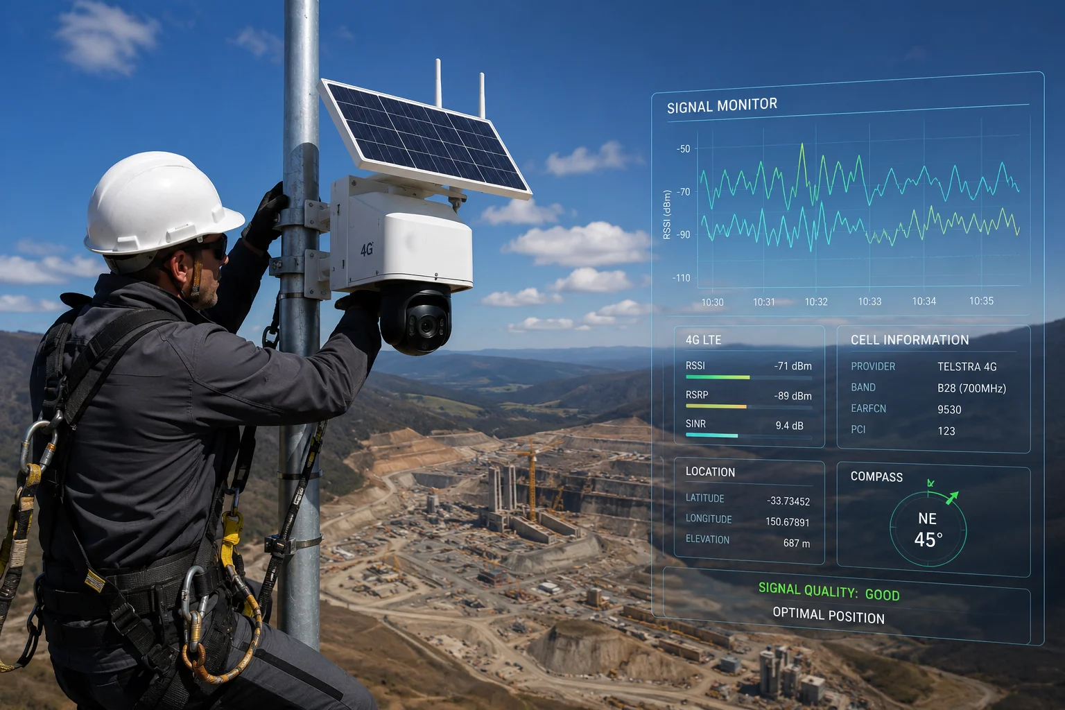 RSSI signal indicators on 4G solar PTZ camera for on-site positioning
Below, I’ll walk you through exactly what those LED indicators can and cannot do. I’ll also share the field-tested methods our integrators use across North America to avoid the most common positioning mistakes. Let’s get into the details.
Table of Contents
Can My Installer See the 4G Signal Strength via LEDs Without Using a Laptop?
Every installer I talk to asks the same thing: “Can I just look at the box and know if the signal is good?” It’s a fair question. Nobody wants to haul a laptop up a 30-foot pole.
Yes, most of our 4G solar PTZ cameras2 have built-in LED indicators on the body that show basic signal strength. Your installer can see at a glance whether the modem has registered on the network and whether the signal level is in an acceptable range. However, these LEDs only reflect RSSI, which is a rough measurement. They do not show the full picture of signal quality.
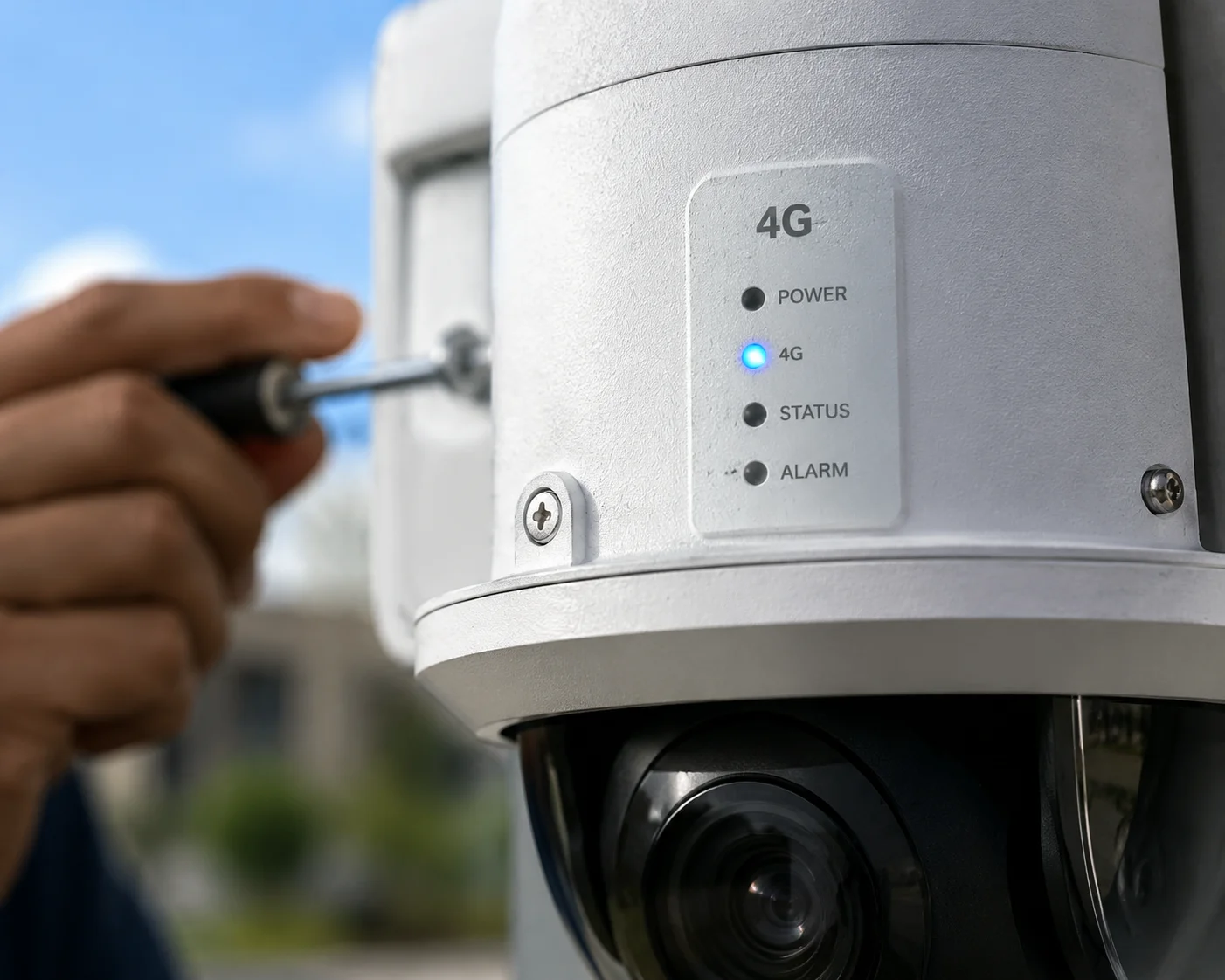 4G PTZ camera LED signal indicator visible without laptop
What the LEDs Actually Tell You
The LEDs on the camera body are designed for speed and convenience. When your installer powers up the unit in the field, the LEDs will cycle through a boot sequence. After about 30 to 60 seconds, the 4G modem registers on the nearest cell tower3. At that point, the signal LED settles into a steady or blinking pattern that represents the RSSI level.
Here is what a typical LED status means on our units:
| LED Behavior | RSSI Range | What It Means |
|---|---|---|
| Solid or fast blink | $> -65\text{dBm}$ | Strong received power. Good starting point. |
| Slow blink | $-65$ to $-85\text{dBm}$ | Moderate received power. Likely usable. |
| Very slow blink or dim | $< -85\text{dBm}$ | Weak received power. Needs further investigation. |
This is helpful for a quick “go or no-go” decision. If the LED shows almost no signal, your installer knows right away that this spot won’t work. But here is the problem: a strong RSSI does not guarantee a smooth video stream.
Why RSSI Alone Is Not Enough
RSSI measures the total power arriving at the antenna. That total power includes the useful signal from the cell tower. But it also includes noise from nearby electronics, high-voltage power lines, metal structures, and even other cell towers on the same frequency.
I’ve seen this happen many times. An installer sees a strong LED indication at a construction site. The RSSI reads $-55\text{dBm}$, which looks excellent. But the site is next to a large industrial facility with heavy electrical equipment. The noise floor is very high. So the actual signal-to-noise ratio is terrible. The camera connects, but the video freezes every few seconds.
The Practical Takeaway
Use the LEDs as a first filter. If the LED shows no signal, move on. If it shows moderate or strong signal, that’s your green light to pull out a phone or tablet and check the deeper metrics through the camera’s web interface or app. The LEDs save your installer from climbing a pole in a dead zone. But they should never be the final word on where to mount the camera.
Think of it this way: the LED tells you “there is radio energy here.” It does not tell you “this radio energy is clean enough to push a 4MP H.2654 stream at 4 Mbps upstream.” For that answer, you need RSRP, RSRQ, and SINR. I’ll explain those in the sections below.
Does the LED Flash Different Colors (Green/Yellow/Red) to Indicate Signal Quality?
I get this question a lot from project managers who want a traffic-light system. Green means go. Red means stop. It sounds simple. But cellular signal quality is not that simple.
On many of our camera models, the LED does use color coding — typically green, yellow (or amber), and red — to give a rough indication of signal strength. Green means the RSSI is strong, yellow means it is moderate, and red means it is weak or the modem has not registered. But these colors still only reflect RSSI, not the deeper quality metrics that determine whether your video will actually stream without interruption.
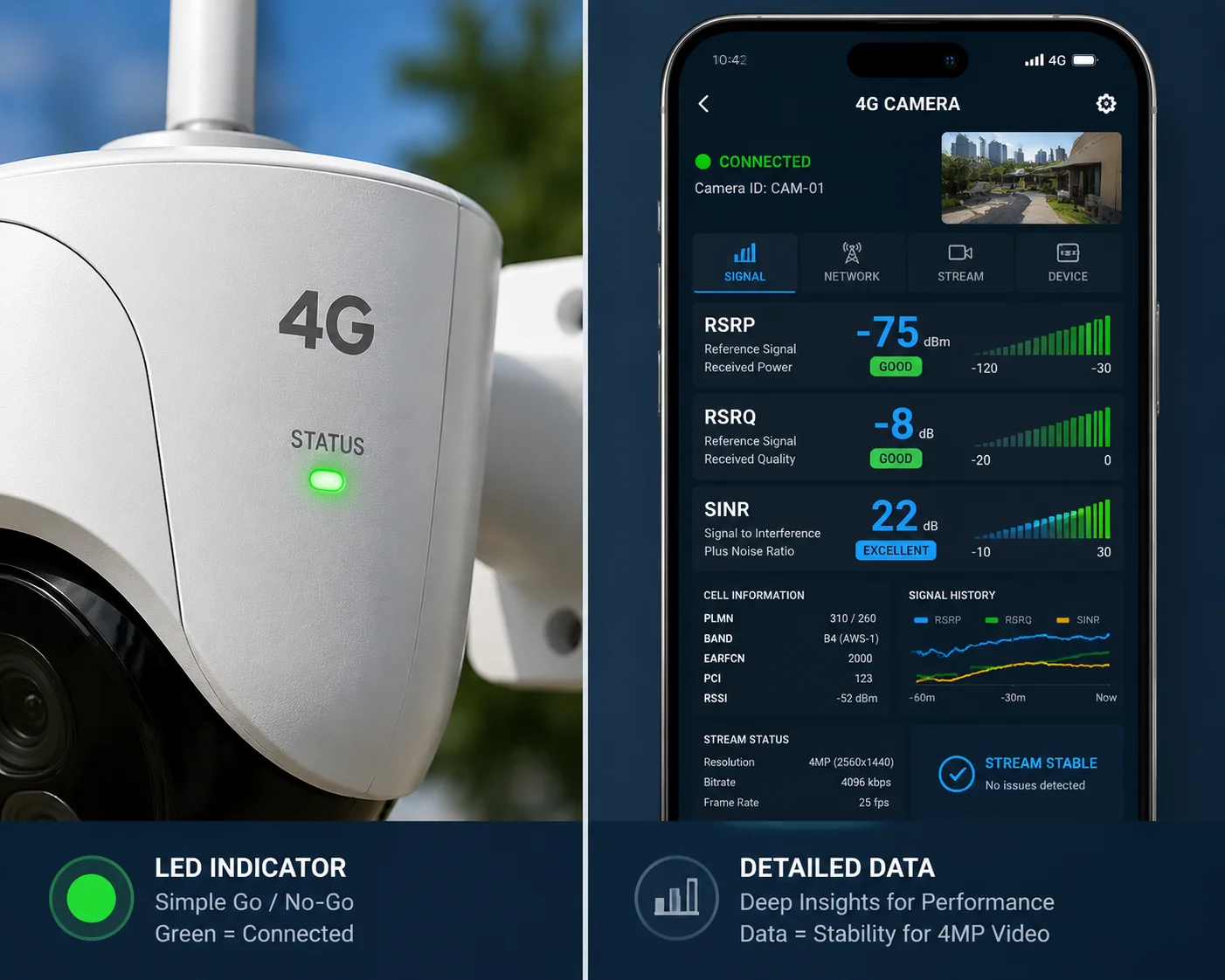 LED color indicators green yellow red on 4G PTZ camera
How the Color System Works
The color-coded LED system is mapped to RSSI thresholds that we set in the firmware. Here is a typical mapping:
| LED Color | RSSI Threshold | Installer Action |
|---|---|---|
| Green | $> -70\text{dBm}$ | Signal looks strong. Proceed to verify SINR via app. |
| Yellow / Amber | $-70$ to $-90\text{dBm}$ | Signal is borderline. Try repositioning or adjusting antenna angle. |
| Red | $< -90\text{dBm}$ or no registration | Signal is too weak. Move to a different location or add an external antenna. |
This gives your installer a fast visual reference. In bright sunlight on a rooftop, it is much easier to see a color than to read a number on a small screen. That is the whole point of the color system. It is designed for speed, not precision.
The Gap Between Color and Reality
Here is where things get tricky. I’ve personally seen a camera show a solid green LED — meaning RSSI above $-70\text{dBm}$ — at a ranch in open terrain. Everything looked perfect. But when we checked the software, the SINR was only $3\text{dB}$. That is very poor. The reason was a nearby cell tower on an adjacent frequency band causing heavy interference. The total received power was high, so the LED was green. But most of that power was interference, not useful signal.
What You Should Do After Seeing the Color
The color LED is step one. Step two is opening the camera’s web interface on your phone or tablet. Navigate to the “4G Status” page. Look at three numbers:
- RSRP (Reference Signal Received Power):[^] Look at three numbers: RSRP5 (Reference Signal Received Power): This isolates just the useful signal from the tower, ignoring noise. You want this above $-100\text{dBm}$ at minimum. Above $-80\text{dBm}$ is excellent.
- RSRQ (Reference Signal Received Quality):[^] RSRQ6 (Reference Signal Received Quality): This tells you how clean the signal is. You want this above $-10\text{dB}$.
- SINR (Signal to Interference plus Noise Ratio):[^] SINR7 (Signal to Interference plus Noise Ratio): This is the most important number. It directly controls your upload speed. You want this above $15\text{dB}$ for reliable 4MP streaming. Above $20\text{dB}$ is ideal.
A green LED with a low SINR is a trap. A yellow LED with a high SINR is actually a better installation spot. I always tell our integrators: trust the numbers on the screen, not the color on the box. The LED gets you in the right neighborhood. The software metrics get you to the right address.
A Real-World Decision Framework
When David is deploying cameras on a remote Texas farm, he might test two pole locations 50 meters apart. Location A shows a green LED. Location B shows a yellow LED. Most installers would pick A without thinking. But if David checks the app and sees that Location A has an SINR of $5\text{dB}$ while Location B has an SINR of $18\text{dB}$, Location B is the clear winner. The video will be smoother, the connection will be more stable, and there will be fewer support calls down the road.
Will the Signal Indicators Help Me Find the Best Orientation for My External Antenna?
Antenna orientation is one of the most overlooked steps in 4G camera installation. I’ve seen a $15 antenna adjustment turn a failing site into a reliable one. But the process has hidden pitfalls.
Yes, the built-in signal indicators can help guide antenna orientation8, but you must use them correctly. The 4G modem applies signal smoothing9, which means the displayed values lag behind physical changes by 3 to 5 seconds. If you rotate the antenna too fast, you will miss the optimal direction. Slow, deliberate rotation combined with software-based SINR monitoring gives the best results.
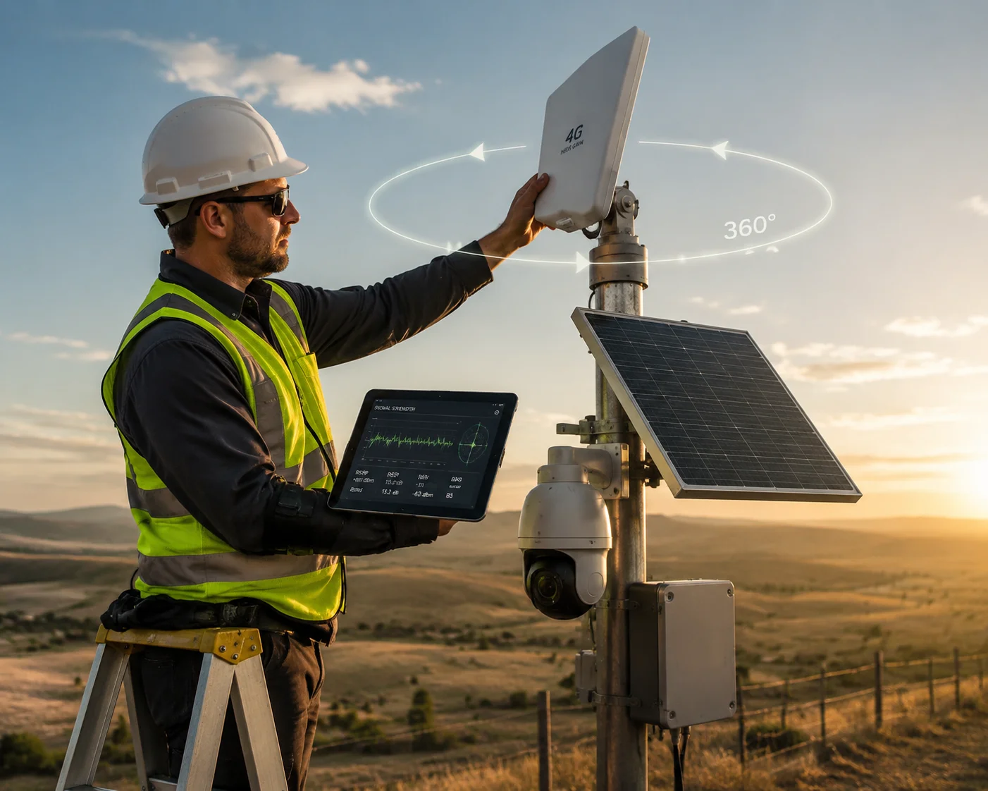 Adjusting external antenna orientation using signal indicators on 4G camera
The Smoothing Delay Problem
When you rotate an external antenna on a pole-mounted camera, the radio signal changes instantly. But the number you see on the screen does not change instantly. The 4G modem inside the camera uses a smoothing algorithm. It averages the signal readings over a short window — usually 2 to 5 seconds — to avoid showing wild fluctuations.
This is helpful during normal operation. You don’t want the signal bar jumping up and down every second. But during antenna alignment, this smoothing becomes a problem. If you rotate the antenna continuously, the displayed value is always showing you the average of where you were a few seconds ago, not where you are right now.
The Correct Rotation Method
Here is the method I recommend to every installer:
- Point the antenna in a starting direction (usually toward the nearest known cell tower).
- Wait 15 seconds. Record the RSRP and SINR values.
- Rotate the antenna $10°$ clockwise.
- Wait 15 seconds again. Record the new values.
- Repeat until you have covered a full $360°$ or at least a $180°$ arc toward the likely tower direction.
- Go back to the angle that produced the highest SINR.
This is slow. A full sweep can take 10 to 15 minutes. But it is the only reliable way to find the true best orientation. Rushing this step is the number one cause of “it worked during install but drops out at night” complaints.
The Human Body Problem
There is another factor that most people don’t think about. When your installer is standing on a ladder next to the antenna, their body absorbs and reflects radio waves. The human body is mostly water, and water is very good at blocking cellular frequencies. This means the signal readings taken while the installer is next to the antenna are not the same as the readings after the installer climbs down.
I always tell our field teams: after you lock the antenna in position, climb down, walk at least 1.5 meters away, and then check the final values through the phone app. The difference can be significant — sometimes 3 to 5 dB on SINR. That is enough to change a marginal connection into a solid one, or vice versa.
Using the LED vs. the App During Rotation
Can you use the LED color alone to find the best angle? Technically, yes. But the LED only reflects RSSI, and it has very coarse resolution. The difference between a green LED at $-65\text{dBm}$ and a green LED at $-60\text{dBm}$ is invisible — both show green. But that $5\text{dB}$ difference in RSRP might correspond to a much larger difference in SINR, depending on the interference environment.
For serious deployments — especially in remote areas where a second truck roll costs hundreds of dollars — I strongly recommend using the app or web interface during antenna alignment. Watch the SINR number in real time. It updates every second on our “4G Status” page. That real-time curve gives you far more useful information than any LED can.
Can the Signal LEDs Be Turned Off in the Software to Maintain a “Stealth” Profile?
This comes up a lot in law enforcement, border monitoring, and anti-theft deployments. A blinking LED at night is like a beacon saying “camera here.” It defeats the whole purpose of covert surveillance.
Yes, on our cameras you can disable all external LEDs through the software interface. This includes the signal indicator LED, the power LED, and the network status LED. Once disabled, the camera operates with no visible light output, which is essential for stealth or covert installations where the camera must remain undetected.
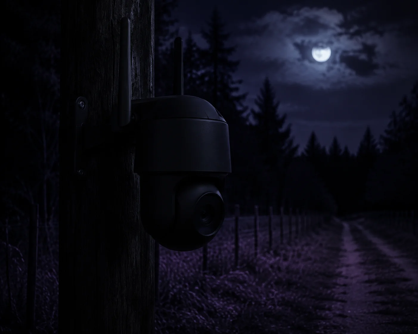 Stealth mode 4G PTZ camera with LEDs turned off for covert deployment
Why Stealth Mode Matters
In many real-world deployments, the camera is not meant to be seen. Construction site theft monitoring, wildlife observation, rural property protection — these all require the camera to blend into its surroundings. A flashing green or red LED, especially at night, draws attention. It can alert intruders to the camera’s location. In the worst case, they destroy or steal the camera before it captures useful evidence.
Our firmware includes a “Stealth Mode” toggle in the system settings. When you enable it, all LEDs on the camera body turn off completely. The camera continues to operate normally — recording, streaming, sending alerts — but with zero visible light output. The IR illuminator for night vision uses wavelengths (850nm or 940nm) that are invisible or nearly invisible to the human eye, depending on the model you choose.
What You Lose When LEDs Are Off
There is a trade-off. When the LEDs are off, your installer loses the quick visual feedback during maintenance visits. If someone needs to check whether the camera is powered on or connected to the network, they can’t just glance at the box. They need to connect via the app or web interface.
Here is a comparison of the two modes:
| Feature | LEDs On (Normal Mode) | LEDs Off (Stealth Mode) |
|---|---|---|
| Quick power status check | Yes — glance at LED | No — must use app |
| Signal strength indication | Yes — color-coded LED | No — must use app |
| Covert deployment suitability | Poor — visible at night | Excellent — no light output |
| Maintenance convenience | High | Lower — requires device access |
How to Configure Stealth Mode
The setting is in the camera’s web interface under System > LED Control. You can also access it through our mobile app. There are usually three options:
- All LEDs On: Normal operation. All status LEDs function as designed.
- All LEDs Off: Full stealth. No visible light from the camera body.
- LEDs On During Boot Only: The LEDs turn on for 60 seconds after power-up (so the installer can confirm the unit is alive), then automatically turn off.
The third option is a good compromise for many deployments. It gives the installer a brief window to verify the camera is working, then goes dark for ongoing operation.
Combining Stealth Mode with Signal Optimization
Here is a workflow I recommend for covert deployments:
- Install the camera with LEDs on. Use the color indicators for initial positioning.
- Connect via the app. Check RSRP, RSRQ, and SINR. Optimize antenna orientation using the method I described above.
- Run a speed test through the camera interface to confirm upload bandwidth meets your video bitrate requirements.
- Once everything is confirmed, enable Stealth Mode10 in the software.
- Do a final visual check at night to make sure no light is leaking from the housing.
This way, you get the benefit of the LEDs during installation, and the benefit of invisibility during operation. You don’t have to choose one or the other.
A Note on IR Illuminator Visibility
Even with all LEDs off, some IR illuminators at 850nm produce a faint red glow that is visible to the human eye at close range. If your deployment requires absolute invisibility, ask us about our 940nm IR models. These produce zero visible glow. The trade-off is slightly shorter IR range, but for covert work, it is usually worth it.
Conclusion
RSSI indicators are a helpful first step, but never the final answer. Always check SINR through the software, rotate your antenna slowly, and switch to Stealth Mode after setup is complete.
1. Understand what RSSI measures and its limitations in cellular positioning. ↩︎ 2. Overview of 4G solar-powered PTZ cameras for remote surveillance. ↩︎ 3. Basics of how cell towers communicate with mobile devices. ↩︎ 4. H.265 video compression reduces bandwidth while maintaining quality, crucial for 4MP streaming. ↩︎ 5. Learn how RSRP isolates the useful signal from the tower, ignoring noise. ↩︎ 6. RSRQ indicates how clean the signal is, beyond just received power. ↩︎ 7. SINR directly controls upload speed and is the most important metric for reliable video streaming. ↩︎ 8. Best practices for rotating and aligning external antennas for optimal signal. ↩︎ 9. Understanding why modem signal readings lag behind real changes during antenna alignment. ↩︎ 10. How to disable all LEDs for covert surveillance to avoid detection. ↩︎