
I have seen metal PTZ cameras go completely silent in the field. No 4G signal. No Wi-Fi. The metal shell killed everything.
A metal PTZ camera avoids the Faraday Cage effect through four core strategies: RF-transparent plastic windows in the housing, external antenna routing via SMA connectors, slot antenna isolation at metal joints, and offset-mounted internal antennas near non-metallic zones. These methods let RF signals pass freely while keeping the full-metal body’s durability intact.
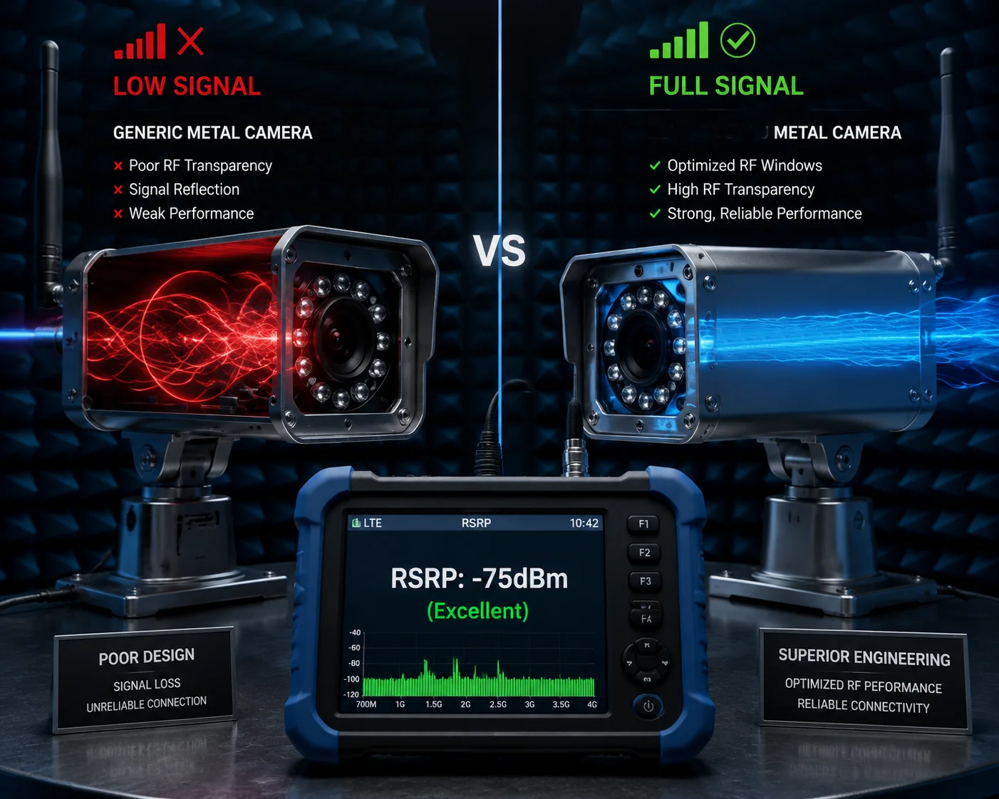
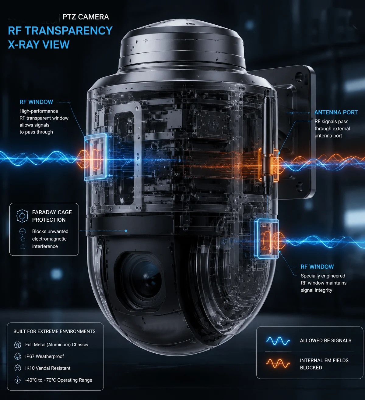 Metal PTZ camera structural design avoiding Faraday Cage effect
Below, I will walk you through each design choice we use at Loyalty-Secu. I will explain why each one matters, how it works in practice, and how you can test it yourself before committing to a bulk order.
Table of Contents
Is the 4G Module Isolated From the Metal Housing to Prevent Signal Absorption?
If your 4G module sits directly against a metal wall, the housing eats the signal. I have measured this myself — signal drops of 10 dB or more in poorly designed units.
Yes, the 4G module must be physically and electrically isolated from the metal housing. At Loyalty-Secu, we use IPEX-to-SMA shielded feed lines to route the RF signal outside the metal body. The module’s RF reference ground is separated from the chassis ground through controlled impedance paths, preventing the metal shell from absorbing or shorting out the signal.
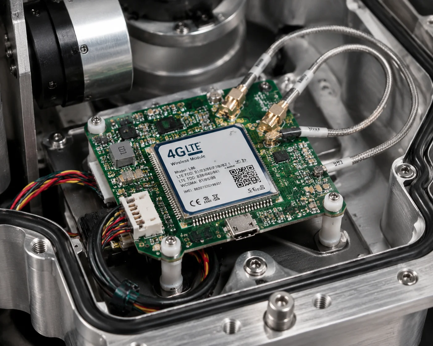 4G module isolation from metal PTZ camera housing
Why Direct Contact Kills Your Signal
Think of a metal PTZ camera body as a closed metal box. In physics, a closed conductive shell blocks electromagnetic waves from entering or leaving. This is the Faraday Cage1 effect.
When a 4G module is bolted directly to the inside wall of this box, two bad things happen at the same time.
First, the antenna’s near-field radiation gets absorbed by the surrounding metal. The energy that should travel outward to a cell tower instead turns into heat inside the chassis. Second, if the antenna’s ground plane merges with the chassis ground without proper impedance control, the entire metal body becomes part of the antenna system — but in an uncontrolled, destructive way. The result is a messy radiation pattern and massive signal loss.
How We Isolate the Module
At Loyalty-Secu, we take a three-layer approach to isolation:
| Layer | Method | Purpose |
|---|---|---|
| Mechanical | Nylon standoffs and rubber gaskets between module and chassis | Prevent direct metal-to-metal contact |
| Electrical | Controlled impedance trace from module RF pin to IPEX connector | Keep the RF path clean and predictable |
| Thermal | Thermally conductive but electrically insulating pads | Allow heat to escape without creating a ground loop |
The key point here is that isolation does not mean the module floats freely. It means every connection between the module and the metal body is intentional and controlled. We decide exactly where current flows. We decide where it does not.
The Ground Loop Trap
One mistake I see from other factories is this: they isolate the antenna but forget about the USB or UART data cables connecting the 4G module to the main processor. These cables can act as unintended antennas. They pick up RF energy and dump it into the chassis ground. The fix is simple — use shielded cables with ferrite choke11s at both ends. But many factories skip this step to save $0.30 per unit. That $0.30 can cost your client 6 dB of signal strength in the field.
For someone like David, who deploys cameras in remote areas where every decibel counts, this is not a small detail. It is the difference between a stable 4G link and a camera that drops offline every afternoon when the cell tower gets busy.
How Do You Ensure the Internal Antennas Can Radiate Through the Metal Body?
Internal antennas inside a metal box sound like a contradiction. I thought so too, until we started using RF-transparent windows and offset mounting together.
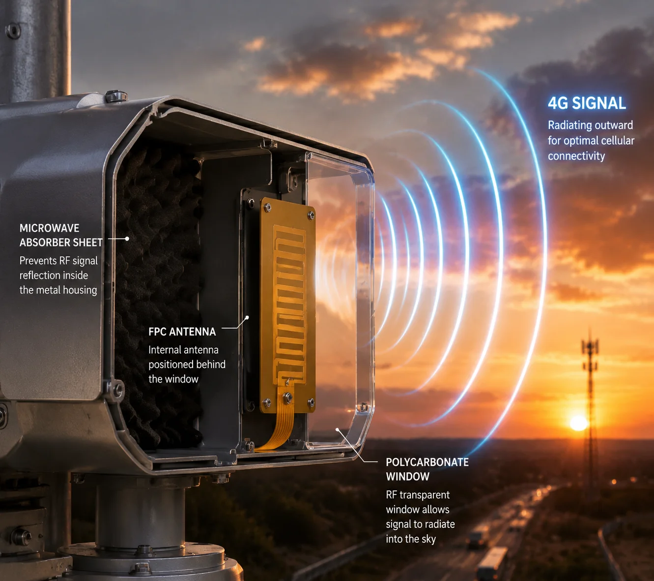
We ensure internal antenna radiation by placing antennas directly behind non-metallic sections of the housing — typically polycarbonate or ABS plastic caps. The antenna is offset-mounted at the edge of the PCB, as far from metal surfaces as possible, with absorber material behind it to prevent destructive reflections inside the cavity.
 Internal antenna radiation through metal PTZ camera body
The RF Window Concept
An RF window is simply a section of the camera housing made from plastic instead of metal. Electromagnetic waves pass through plastic almost as easily as they pass through air. So if you place your antenna right behind a plastic window, the signal goes out with very little loss.
The challenge is making this window strong enough and sealed enough to maintain the camera’s IP663 rating. We use polycarbonate6 (PC) for most of our RF windows. PC is strong enough to handle impact, UV-resistant for outdoor use, and nearly invisible to RF signals in the 700 MHz to 2600 MHz range that 4G LTE2 uses.
Where We Place the Windows
The location of the RF window matters a lot. You cannot just put it anywhere. The window must face the direction where the antenna needs to radiate. For a PTZ camera mounted on a pole, the strongest signal path is usually horizontal — toward the nearest cell tower. So we place the RF window on the upper body of the camera, above the pan-tilt mechanism, where it has a clear line of sight in all horizontal directions.
Offset Mounting: Getting the Antenna Away From Metal
Even with an RF window, the antenna still sits inside a partially metal cavity. Metal surfaces near the antenna cause reflections. These reflections can add up constructively (good) or destructively (bad). To minimize destructive interference, we mount the FPC (Flexible Printed Circuit) antenna at the very edge of the PCB, pressed against the plastic window.
We also place a thin sheet of microwave absorber9 material on the metal wall behind the antenna. This absorber converts reflected RF energy into a tiny amount of heat, instead of letting it bounce back and cancel out the direct signal.
Performance Comparison: Window vs. No Window
| Configuration | RSRP Loss vs. Free Air | Practical Impact |
|---|---|---|
| Antenna behind full metal wall | -15 dB to -25 dB | Camera cannot maintain 4G connection |
| Antenna behind RF window (no absorber) | -3 dB to -6 dB | Usable, but marginal in weak signal areas |
| Antenna behind RF window (with absorber + offset mount) | -0.5 dB to -1.5 dB | Near-ideal performance, passes OTA testing |
The third configuration is what we ship. It costs more in materials and assembly time, but it means David’s cameras stay online in rural Montana or a construction site in northern Alberta — places where signal is already weak.
Are There Non-Metallic “Windows” in the Housing for RF Signals to Pass Through?
Every time I show a client our camera, they ask the same thing: “It looks all-metal — where does the signal get out?” The answer is hiding in plain sight.
Yes, there are non-metallic windows built into the housing. These are precision-molded polycarbonate or ABS plastic sections integrated into the camera’s top cap or antenna mount zone. They are sealed with industrial-grade gaskets to maintain IP66 protection, and they are visually matched to the metal finish so the camera looks like a single-material design.
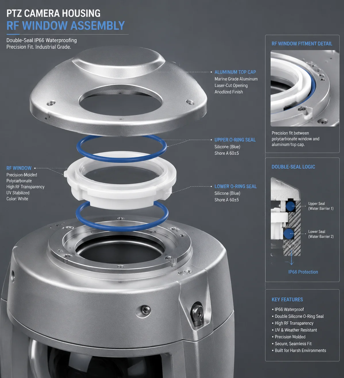 Non-metallic RF windows in metal PTZ camera housing
Why Not Just Use an External Antenna for Everything?
External antennas work great. They are the most reliable way to beat the Faraday Cage effect. But they have drawbacks in certain deployments:
- Vandalism risk: A visible antenna stub can be snapped off.
- Wind loading: On tall poles in high-wind areas, every protruding part adds stress to the mount.
- Aesthetics: Some smart city projects require a clean, integrated look with no visible antennas.
This is why RF windows exist. They give you the signal performance of an external antenna with the clean look of a sealed metal body.
How We Build the Window Into the Housing
The process starts in our mold shop. We design the metal housing with a precise cutout — usually 40 mm × 60 mm for a 4G LTE antenna, or 25 mm × 25 mm for Wi-Fi. The plastic window is injection-molded separately, then press-fitted into the cutout with a silicone gasket compressed to a specific thickness.
Material Selection for the Window
Not all plastics are equal when it comes to RF transparency. Here is what we have tested:
| Material | RF Loss at 2.4 GHz | UV Resistance | Impact Strength | Cost |
|---|---|---|---|---|
| Polycarbonate (PC) | 0.3 dB | Excellent (with UV coating) | Very High | Medium |
| ABS | 0.4 dB | Moderate | High | Low |
| Nylon (PA66) | 0.8 dB | Good | High | Medium |
| Acetal (POM) | 1.2 dB | Poor | Medium | Low |
We use PC for most outdoor PTZ cameras. It gives us the lowest RF loss and the best durability. ABS is our choice for cost-sensitive indoor models.
The Seal Must Not Fail
An RF window is a potential weak point for water ingress. If the gasket fails, water enters the electronics cavity and the camera dies. This is why we use a double-seal design: one O-ring on the outer edge of the window, and one on the inner edge. Even if the outer seal degrades after years of sun exposure, the inner seal keeps water out.
We test every unit in a simulated rain chamber at 100 liters per square meter per minute for 30 minutes. If any moisture enters, the unit fails QC and goes back to the line. For David’s team, this means one less reason to send a technician up a pole in January.
Slot Antennas: The Hidden Alternative
In some of our higher-end models, we skip the plastic window entirely and use the metal housing itself as the antenna. This is called a slot antenna5. The idea is simple: if you cut a narrow slot in a metal sheet and feed RF energy across the slot, the slot radiates like a dipole antenna.
We create these slots at the joints between metal parts — for example, where the dome meets the base. A thin insulating gasket (0.5 mm polyimide) separates the two metal sections. The gap becomes the slot. If the slot length is tuned to half the wavelength of the target frequency (about 83 mm for 1800 MHz LTE), it radiates efficiently.
This approach is elegant, but it requires very precise mechanical tolerances. A 1 mm change in slot width can shift the resonant frequency by 50 MHz. This is why we keep this design for our premium product lines where we control every dimension in-house.
Why Do Some All-Metal Cameras Experience 50% Signal Loss Compared to Plastic Ones?
I have tested competitor cameras that lose half their signal strength the moment you close the metal housing. That is not a design trade-off. That is a design failure.
Some all-metal cameras lose 50% (3 dB) or more of their signal because they lack any RF mitigation strategy — no plastic windows, no external antenna ports, no slot antenna design. The metal housing forms a complete Faraday Cage around the internal antenna, and the signal has nowhere to go. This is a pure engineering oversight, not an unavoidable consequence of using metal.
 Signal loss comparison between metal and plastic PTZ cameras
The Physics Behind 50% Loss
A 50% signal loss equals 3 dB. But in practice, many poorly designed metal cameras lose far more than 3 dB. I have measured losses of 12 dB to 18 dB in some units — that is a 94% to 98% reduction in signal power. At that point, the 4G module cannot even register on the network.
The reason is straightforward. A metal enclosure with no RF openings reflects almost all electromagnetic energy back into the cavity. The small amount of energy that does leak out escapes through tiny gaps — screw holes, cable glands, seam imperfections. But these leakage paths are random and uncontrolled. They do not form a useful radiation pattern. The signal that escapes goes in unpredictable directions, and most of it is wasted.
Why Do Factories Still Make This Mistake?
There are three common reasons:
Cost pressure. Adding an RF window, an SMA connector, or a slot antenna design adds $2 to $5 to the BOM (Bill of Materials). Some factories cut this to win price wars. The camera looks identical on the outside, but the RF performance is crippled.
Lack of RF expertise. Many camera factories are strong in optics and video processing but weak in RF engineering. They buy a 4G module from a supplier, solder it onto the main board, and assume it will work. They never run an OTA test. They never measure RSRP with the housing closed vs. open.
Copy-paste design. Some factories copy the mechanical design of a plastic camera and simply swap the material to metal. The plastic version worked fine because the entire housing was RF-transparent. The metal version fails because nobody redesigned the antenna system.
How David Can Spot This Problem Before Buying
I always tell my clients: do not trust the datasheet alone. Ask for one simple test result.
Ask the factory to provide RSRP7 readings with the antenna inside the closed housing and with the antenna pulled outside the housing through a temporary cable. The difference between these two numbers tells you everything.
- Less than 1 dB difference: Excellent RF design. The housing is not hurting the signal.
- 1 dB to 3 dB difference: Acceptable. The camera will work in most conditions.
- More than 3 dB difference: The housing is a problem. Walk away.
At Loyalty-Secu, we run this test on every new design during the prototype phase. We also run full OTA testing10 in an anechoic chamber8 to measure the 3D radiation pattern. Our target is less than 1 dB of housing-induced loss. We publish these results for any client who asks.
The Ground Plane Advantage: When Metal Actually Helps
Here is something most people do not expect: a metal housing can actually improve antenna performance — if the antenna is outside the housing.
When you mount an external antenna on top of a metal camera body, the body acts as a ground plane4. A ground plane reflects the antenna’s downward radiation upward, concentrating the signal toward the horizon where cell towers are. This can add 2 dB to 4 dB of gain compared to the same antenna floating in free space.
This is why our external-antenna models often outperform plastic cameras in real-world tests. The metal body is not a liability. It is a feature — but only if the antenna is on the outside.
Conclusion
Metal PTZ cameras do not have to suffer from the Faraday Cage effect. With RF windows, external antenna routing, slot antennas, and proper isolation, a metal body can match or even beat plastic in signal performance. Ask your factory for RSRP test data — the numbers never lie.
1. Understand the electromagnetic shielding principle that blocks RF signals in metal enclosures. ↩︎ 2. Learn about the 4G wireless standard used in cellular cameras. ↩︎ 3. Understand the ingress protection rating for dust and water resistance in outdoor cameras. ↩︎ 4. Learn how a metal surface can improve antenna radiation when properly designed. ↩︎ 5. Explore how a cut in a metal surface can be used as an efficient radiating element. ↩︎ 6. Read about the thermoplastic commonly used for RF-transparent windows due to its low RF loss and durability. ↩︎ 7. Understand the key metric for measuring LTE signal strength in the field. ↩︎ 8. Learn about the controlled environment used for accurate antenna radiation pattern testing. ↩︎ 9. Understand how absorber materials reduce reflected energy inside cavities to improve antenna efficiency. ↩︎ 10. Learn about over-the-air testing methods to validate real-world wireless performance. ↩︎ 11. Discover how ferrite chokes suppress high-frequency noise on cables to prevent signal degradation. ↩︎