
I have deployed PTZ cameras in places where cell signal barely exists. Remote farms, deep forests, mountain ridges. At -110dBm, most cameras just die.
At -110dBm RSRP, a 4G PTZ camera can still push a low-bitrate video stream — but only if it has high-gain antennas, adaptive bitrate firmware, and robust reconnection logic. Without these, expect frozen frames, constant buffering, and frequent disconnections that make the feed almost useless.
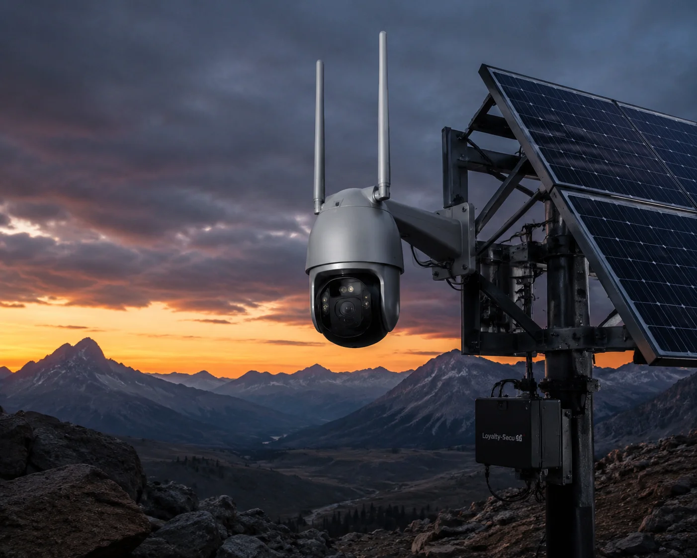 4G PTZ camera streaming in ultra-weak signal environment
Below, I break down exactly what happens at -110dBm — from sub-stream stability to packet loss, firmware behavior, and P2P retry logic. If you are planning a deployment in a dead zone, this is the guide you need before you buy.
Table of Contents
Can the Camera Maintain a 1080p Sub-Stream Without Crashing When the RSRP Is -110dBm?
I have watched cameras crash and reboot in loops when the signal drops below -105dBm. A 1080p sub-stream at -110dBm is not a given. It is a fight.
A 1080p sub-stream at -110dBm is possible but not reliable on stock hardware. The camera must drop to 720p or 640×480, cut the bitrate to 256–512kbps, and use H.265+ encoding. Without a high-gain antenna3 upgrade, the stream will freeze or crash within minutes.
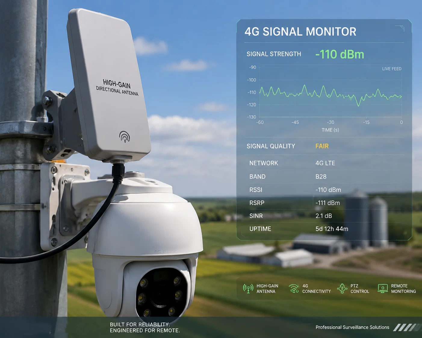 4G camera sub-stream performance in weak signal
What -110dBm Actually Means for Your Link Budget
Let me put -110dBm in context. This is not just “low signal.” This is the edge of what a 4G modem can even detect. The noise floor on most LTE modules sits around -115 to -120dBm. So at -110dBm, your signal-to-noise ratio (SNR) is only about 5–10dB. That is barely enough for the modem to maintain a connection, let alone push video.
Here is what happens at the physical layer:
| RSRP Range | Signal Quality | What You Can Expect |
|---|---|---|
| -80 dBm or better | Good | Stable 1080p main stream, smooth PTZ control |
| -90 to -80 dBm | Fair | 1080p sub-stream works, occasional stutter |
| -100 to -90 dBm | Poor | Must use sub-stream, frequent bitrate drops |
| -110 to -100 dBm | Very Poor | Sub-stream barely holds, heavy packet loss |
| -110 dBm or worse | Edge / Dead Zone | Stream crashes without hardware upgrades |
At -110dBm, the LTE modem drops to the lowest modulation scheme — QPSK with heavy coding. This means your actual uplink speed might be only 200–500kbps. A 1080p sub-stream at 25fps typically needs at least 512kbps to 1Mbps. So the math does not work unless you make changes.
The Hardware Fix: Antennas Matter More Than the Modem
The stock rubber-duck antenna on most 4G cameras gives you 3–5dBi of gain. At -110dBm, that is not enough. I always tell my clients: swap it for a 12–15dBi high-gain omnidirectional antenna or a directional panel antenna pointed at the nearest cell tower.
This single change can improve your effective signal by 8–10dB. That moves you from -110dBm to roughly -100dBm at the modem input. That is the difference between “unusable” and “it works.”
Also, make sure the 4G module supports MIMO — dual-antenna diversity reception. Even if one antenna path fades due to multipath interference, the other path can still capture the signal. This adds about 3–5dB of SNR improvement.
The Firmware Fix: H.265+ and Forced Sub-Stream
On the software side, the camera firmware must do several things automatically:
- Force sub-stream mode7 when RSRP1 drops below -100dBm. The main stream at 4Mbps will choke the uplink instantly.
- Enable H.265+ encoding2 at maximum compression. This can cut the bitrate by 50–70% compared to H.264, giving you a usable 720p stream at just 256kbps.
- Reduce the frame rate from 25fps to 10–15fps. Each frame you remove saves precious bandwidth.
Without these automatic adjustments, the camera will try to push too much data through a tiny pipe. The buffer overflows. The stream freezes. The modem resets. The camera crashes.
What Is the Packet Loss Rate of Your 4G PTZ in “Dead Zone” Areas With Minimal Cellular Bars?
I have tested packet loss in areas where my phone shows zero bars. The numbers are ugly. But they are real, and you need to know them before you commit to a site.
In dead zone areas with RSRP around -110dBm, packet loss on 4G PTZ cameras typically ranges from 15% to 30%. This causes visible artifacts, frozen frames, and audio dropouts. Forward Error Correction (FEC)6 can recover about half of the lost packets, but the stream will still show noticeable quality degradation.
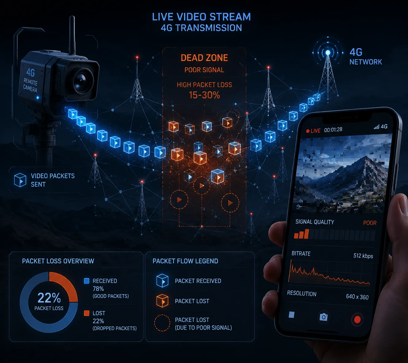 Packet loss testing in dead zone cellular area
Why Packet Loss Spikes at -110dBm
At -110dBm, the LTE radio link is operating at its absolute minimum. The base station and the modem are both struggling. The error rate on the air interface goes up sharply. The modem uses HARQ (Hybrid Automatic Repeat Request)8 to retransmit corrupted packets, but each retransmission adds latency. When too many packets need retransmission at the same time, the system gives up on some of them. Those become lost packets.
For video streaming, packet loss4 hits differently depending on the transport protocol:
TCP vs. UDP: Which Suffers More?
| Protocol | Behavior at 15–30% Packet Loss | Impact on Video |
|---|---|---|
| TCP (used by some RTSP, HTTP streams) | Retransmits every lost packet, shrinks window | Stream pauses, long buffering, high latency |
| UDP (used by RTP, some P2P streams) | Drops lost packets, no retransmission | Mosaic artifacts, frozen frames, glitches |
| UDP + FEC (forward error correction) | Sends redundant data to recover losses | Better quality, but uses 20–30% more bandwidth |
Most cheap 4G cameras use plain UDP for video transport. At 20% packet loss, you will see blocky artifacts every few seconds. The I-frames (keyframes) are the most critical. If an I-frame is lost, every following P-frame becomes garbage until the next I-frame arrives. That is why you see the screen turn into a mosaic and stay that way for several seconds.
How FEC Helps — and Its Limits
A well-designed 4G PTZ camera uses FEC to fight packet loss. FEC works by sending extra redundant packets alongside the real data. If some packets are lost, the receiver can reconstruct the missing data from the redundant packets.
At 15% packet loss, FEC with 20% redundancy can recover almost all lost packets. But at 25–30% packet loss, even 30% FEC redundancy is not enough. And adding more redundancy means using more bandwidth — which you do not have at -110dBm.
This is the core trade-off in dead zone deployments. You are always balancing between video quality, latency, and reliability. There is no magic solution. The physics of the radio link sets a hard limit.
What I Recommend to My Clients
For sites where packet loss consistently exceeds 20%, I suggest these steps:
- Store all recordings locally on the camera’s SD card or onboard NVR. Do not rely on cloud recording over 4G in a dead zone.
- Use 4G only for alarm-triggered short clips and low-resolution live preview.
- Set the I-frame interval to 1 second (GOP = frame rate). This means even if you lose an I-frame, the next one comes quickly and the picture recovers faster.
Does the Firmware Automatically Adjust the Bitrate and I-Frame Interval in Weak Signal Conditions?
I have seen too many cameras that just keep pushing 4Mbps into a 300kbps pipe. The result is always the same: buffer overflow, stream crash, reboot loop. Smart firmware is the difference between a working camera and an expensive paperweight.
Yes — properly engineered 4G PTZ firmware will automatically reduce the bitrate from 4Mbps down to 256–512kbps, increase the I-frame interval, and lower the frame rate when it detects RSRP below -100dBm. This adaptive bitrate control5 (ABR) is essential for maintaining any usable stream in weak signal conditions.
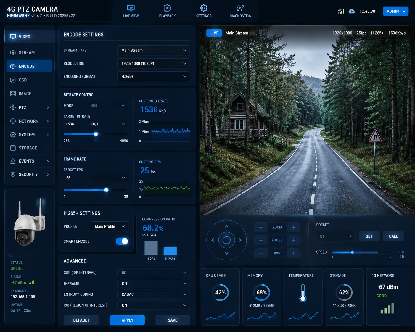 Firmware adaptive bitrate control in weak signal
How Adaptive Bitrate Control Works in Practice
The camera’s firmware continuously monitors two things: the RSRP value reported by the 4G modem, and the actual uplink throughput. When either drops below a set threshold, the firmware triggers a series of adjustments.
Here is the typical sequence:
- RSRP drops below -95dBm: The firmware switches from main stream to sub-stream automatically. Resolution drops from 1080p to 720p or 640×480.
- RSRP drops below -100dBm: Bitrate is reduced to 512kbps or lower. Frame rate drops to 15fps.
- RSRP drops below -105dBm: H.265+ encoding is forced on. Bitrate drops to 256kbps. Frame rate drops to 10fps.
- RSRP drops below -110dBm: The camera enters “survival mode.” It may stop live streaming entirely and only upload alarm-triggered snapshots or 5-second clips.
The I-Frame Interval Problem
The I-frame interval (also called GOP length) is a critical but often overlooked setting. An I-frame is a complete image. P-frames and B-frames only contain the changes from the previous frame. If an I-frame is lost due to packet loss, every frame after it is corrupted until the next I-frame arrives.
In strong signal conditions, a typical GOP length is 2–3 seconds (e.g., 50–75 frames at 25fps). This is efficient because I-frames are large and use a lot of bandwidth.
But at -110dBm, a 3-second GOP is dangerous. If you lose the I-frame, you get 3 seconds of garbage on screen. Smart firmware shortens the GOP to 1 second or even 0.5 seconds in weak signal mode. This means more I-frames, which uses more bandwidth per frame, but recovery from packet loss is much faster.
What Most Cheap Cameras Get Wrong
Many budget 4G cameras from China have a fixed bitrate setting. The firmware does not monitor RSRP at all. It just pushes whatever bitrate the user configured, regardless of the actual network condition. This is the number one reason cameras crash in weak signal areas.
When I evaluate a 4G PTZ for a client, I always ask the factory three questions:
- Does the firmware support automatic bitrate reduction based on RSRP?
- What is the minimum bitrate the encoder can output?
- Can the I-frame interval be adjusted dynamically, or is it fixed?
If the answer to any of these is “no,” that camera is not suitable for dead zone deployment. Period.
The Role of H.265+ in Bandwidth Savings
H.265+ (also called Smart H.265 or H.265 Plus) is not just a marketing term. It is a real encoding optimization that analyzes scene complexity and reduces bitrate for static scenes. In a typical outdoor surveillance scene where most of the frame is sky, trees, or empty ground, H.265+ can reduce the bitrate by 50–70% compared to standard H.265.
At -110dBm, this is the difference between a stream that works and one that does not. A 720p stream at standard H.265 might need 1Mbps. With H.265+, the same stream can run at 300–400kbps. That fits within the available uplink bandwidth at -110dBm.
How Many Retries Will the P2P Server Attempt Before Timing Out in a Low-Signal Scenario?
I have stared at a spinning loading icon on my phone for 45 seconds, waiting for a P2P connection that never came. In low-signal areas, the P2P handshake is the weakest link in the entire chain.
Most P2P platforms used by Chinese 4G PTZ cameras attempt 3 to 5 connection retries with a total timeout of 30 to 60 seconds. If the camera’s uplink is too slow to complete the handshake, the P2P server gives up and returns a “device offline” error — even though the camera is technically still connected to the 4G network.
 P2P server retry and timeout in low signal scenario
How P2P Connections Work in 4G Cameras
When you open your phone app and tap on a camera, here is what happens behind the scenes:
- Your phone sends a request to the P2P cloud server (usually run by the camera manufacturer or a third-party platform like ThroughTek TUTK9, Agora, or a proprietary system).
- The P2P server looks up the camera’s device ID and checks if it has an active heartbeat connection.
- The server tries to establish a direct peer-to-peer tunnel between your phone and the camera. This involves NAT traversal (hole punching).
- If direct P2P fails, the server falls back to relay mode — routing the video through the cloud server.
At -110dBm, every step of this process is slow and unreliable.
Where the Timeout Happens
The P2P handshake requires several round trips between the camera, the server, and your phone. Each round trip at -110dBm can take 500ms to 2 seconds instead of the normal 50–100ms. If the total handshake takes longer than the server’s timeout window, the connection fails.
| P2P Stage | Normal Latency | Latency at -110dBm | Failure Risk |
|---|---|---|---|
| Camera heartbeat to server | 50–100ms | 500ms–2s | Heartbeat may expire, server marks camera offline |
| NAT traversal / hole punch | 200–500ms | 2–5s | Often fails, falls back to relay |
| Relay stream setup | 100–300ms | 1–3s | Relay server may timeout |
| First video frame delivery | 500ms–1s | 5–15s | User sees black screen, gives up |
The total time from tapping “view” to seeing the first frame can be 10–30 seconds at -110dBm. Many users will close the app before the stream even starts.
The Watchdog and Auto-Reconnect Problem
When the 4G modem loses its connection to the base station (which happens frequently at -110dBm), the camera must detect the loss and reconnect. This is where the firmware’s watchdog function becomes critical.
A good watchdog does the following:
- Monitors the modem’s registration status every 5–10 seconds.
- If the modem reports “no service” for more than 15–30 seconds, the watchdog resets the modem hardware.
- After reset, the modem re-registers with the network and re-establishes the P2P heartbeat.
- The entire recovery cycle takes 30–90 seconds.
During this recovery window, the camera is completely offline. No live view, no alerts, no cloud uploads. If the signal is so weak that the modem keeps dropping and reconnecting, the camera can spend more time offline than online.
Dual-SIM Failover: A Real Solution for Dead Zones
For critical deployments in dead zone areas, I always recommend dual-SIM 4G cameras. In the United States, AT&T and Verizon often have complementary coverage. A location where AT&T shows -110dBm might have Verizon at -95dBm, or vice versa.
A dual-SIM camera can automatically switch to the stronger carrier when the primary SIM’s signal drops below a threshold. This does not eliminate the problem, but it significantly reduces the total offline time.
However, most budget 4G cameras from China only support a single SIM. Dual-SIM models are available but cost more. For a system integrator deploying in remote North American sites, the extra cost is worth it. One truck roll to a remote farm to fix a dead camera costs more than the price difference between a single-SIM and dual-SIM model.
My Practical Advice for P2P in Weak Signal
- Do not rely on P2P live view as your primary monitoring method in dead zones. Use local SD card recording and download clips when the signal improves.
- Set the camera to upload only alarm-triggered snapshots and short video clips (5–10 seconds) via 4G. This requires far less bandwidth than continuous streaming.
- If real-time viewing is essential, schedule it during off-peak hours when the cell tower is less congested. Network congestion at -110dBm makes an already bad situation worse.
- Test the P2P platform’s timeout settings before deployment. Some platforms allow you to extend the timeout from 30 seconds to 120 seconds. This gives the camera more time to complete the handshake in weak signal conditions.
Conclusion
At -110dBm, no 4G PTZ camera works perfectly out of the box. But with high-gain antennas, adaptive firmware, H.265+ encoding, and smart deployment strategies, you can still get a usable — if imperfect — surveillance stream from the edge of cellular coverage. Choose your hardware carefully, test before you commit, and always have a local recording fallback.
1. Understand Reference Signal Received Power, the key metric for 4G signal strength. ↩︎ 2. Learn how H.265+ reduces bitrate by up to 70% for bandwidth-constrained streams. ↩︎ 3. See how high-gain antennas improve signal reception in weak areas. ↩︎ 4. Explore how packet loss affects video quality and what you can do about it. ↩︎ 5. Discover how ABR adjusts resolution and bitrate based on signal strength. ↩︎ 6. Learn how FEC recovers lost packets with redundant data. ↩︎ 7. Learn how forcing sub-stream saves bandwidth when signal drops. ↩︎ 8. See how retransmissions cause latency and packet loss. ↩︎ 9. Check one common P2P platform used in 4G cameras. ↩︎