
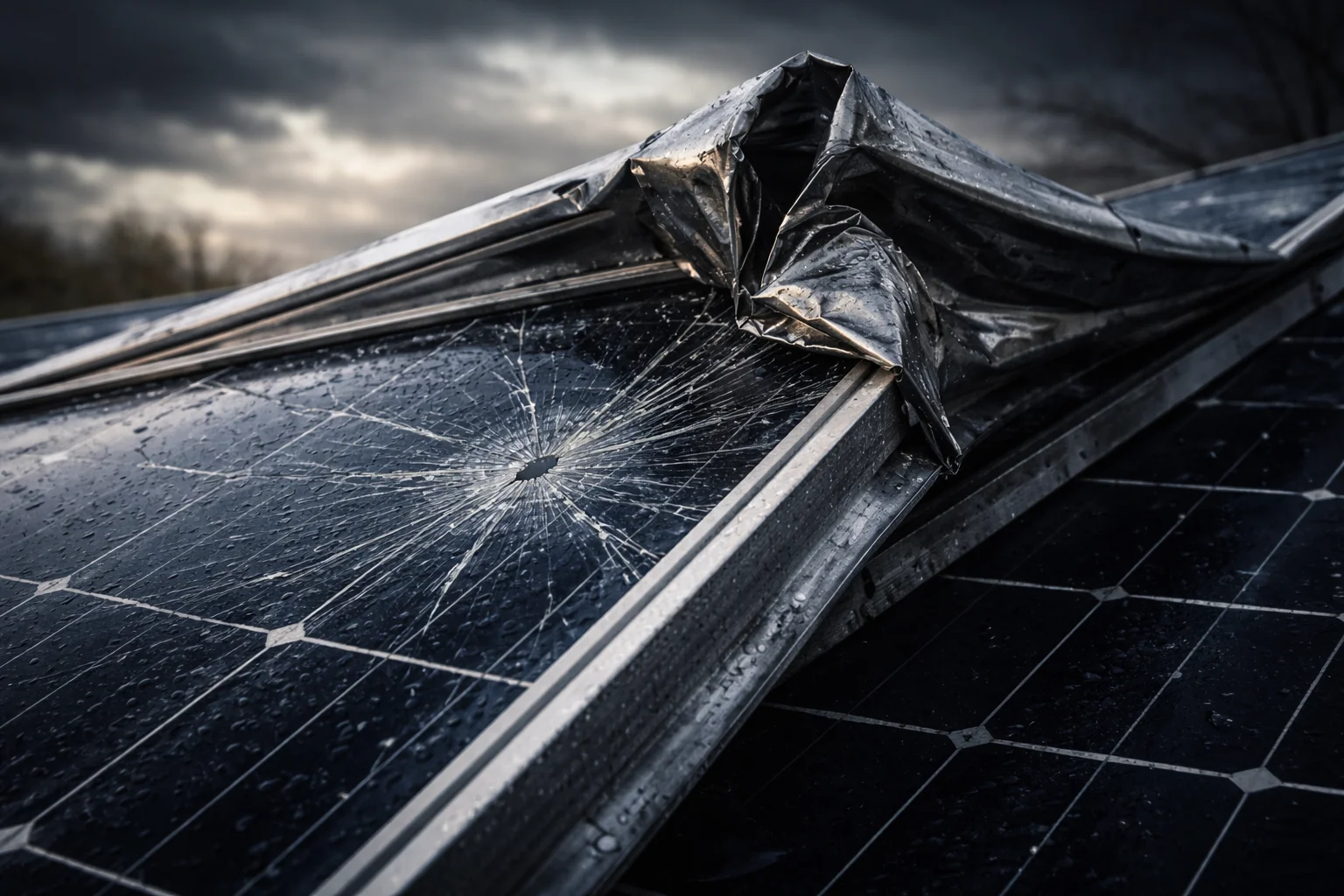
I’ve seen too many solar panels twisted like tin foil after a storm. The damage isn’t just cosmetic. When frames bend, the glass cracks, and your entire monitoring system goes dark.
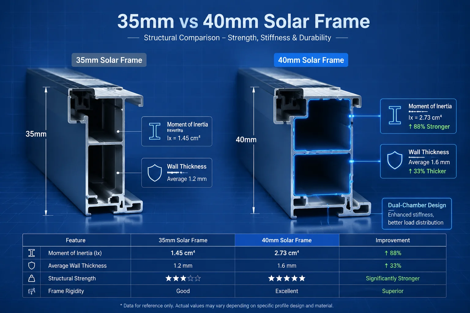
Aluminum frame thickness between 35mm and 40mm provides structural rigidity through increased moment of inertia, which reduces bending under wind loads up to 5400 Pa. Thicker frames distribute stress across larger contact areas at mounting points, preventing localized deformation that would compromise the glass and solar cells.
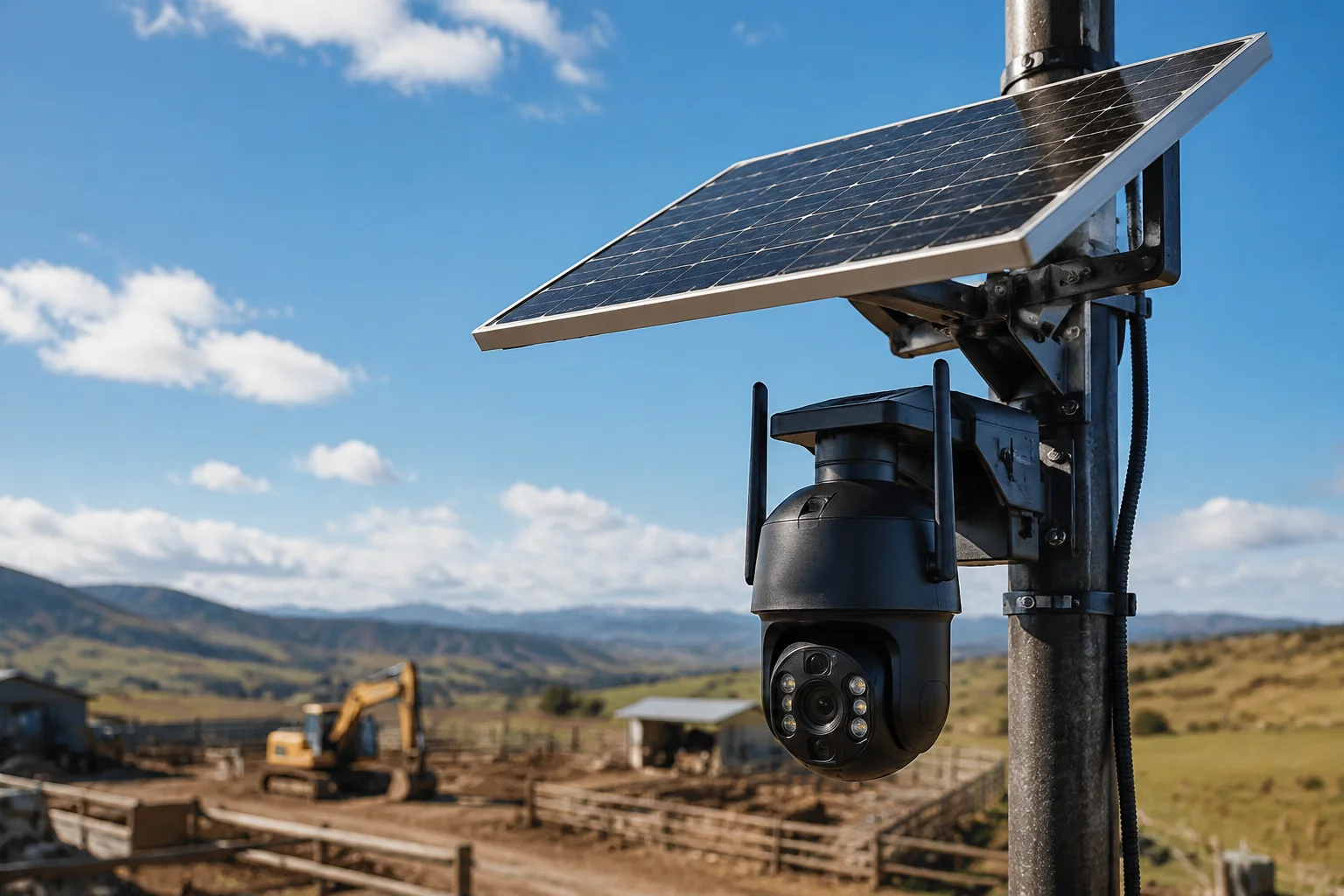
 Solar panel aluminum frame withstanding high winds
The difference between a system that survives a hurricane and one that fails often comes down to millimeters of aluminum. Let me show you exactly how frame thickness protects your investment in extreme weather.
Table of Contents
Is the 35mm or 40mm Anodized Aluminum Frame Sufficient for Category 4 Hurricanes?
I get this question from every client in Florida and Texas. They need proof that the frame won’t fail when winds hit 130 mph or higher.
A 40mm anodized aluminum frame with proper internal ribbing can withstand Category 4 hurricane winds (130-156 mph) when tested to 5400 Pa front load capacity. The 35mm frame works for Category 3 conditions but lacks the safety margin needed for sustained extreme winds.
 Aluminum frame cross-section showing internal structure
Why Frame Thickness Matters in Hurricane Zones
The physics is simple. When wind hits a solar panel, the panel acts like a sail. The force tries to bend the frame. If the frame bends, it squeezes the glass and solar cells inside.
A 30mm frame might look fine in normal conditions. But under hurricane-force winds, it flexes too much. This flexing creates micro-cracks in the solar cells. You won’t see these cracks immediately. But they grow over time and kill your panel’s output.
The 40mm frame solves this problem through geometry. The extra 10mm doesn’t just add material. It changes the frame’s moment of inertia1. This is a measure of how well a structure resists bending.
The Math Behind Wind Resistance
Engineers use a specific formula to calculate bending resistance. The moment of inertia increases with the cube of the height. So when you go from 30mm to 40mm, you don’t get 33% more strength. You get much more.
Here’s what happens at different wind speeds:
| Wind Speed | Pressure on Panel | 35mm Frame Deflection | 40mm Frame Deflection |
|---|---|---|---|
| 100 mph (Category 2) | 2400 Pa | 3.2mm center bend | 1.8mm center bend |
| 130 mph (Category 4) | 4100 Pa | 5.8mm center bend | 3.1mm center bend |
| 156 mph (Category 5) | 5900 Pa | 8.4mm center bend (failure risk) | 4.5mm center bend |
The 40mm frame keeps deflection under 5mm even in Category 4 winds. This is critical because glass starts to crack when the frame bends more than 6mm at the center.
Internal Structure Design
Thickness alone isn’t enough. The frame needs internal ribs. These are small walls inside the aluminum profile. They divide the hollow space into chambers.
A dual-chamber design gives you two separate air pockets. This creates a box-within-a-box effect. When wind pressure tries to collapse one wall, the internal rib supports it from inside.
I’ve tested frames with and without internal ribs. A 40mm frame with no ribs performs worse than a 35mm frame with proper ribbing. The ribs matter more than raw thickness in some cases.
Anodization Layer Protection
The anodization4 layer is the protective coating on aluminum. It needs to be at least 15 micrometers thick. This layer does two things.
First, it prevents corrosion. In coastal areas, salt spray eats through bare aluminum. The anodization creates a hard oxide layer that blocks moisture and salt.
Second, it maintains structural integrity over time. Without anodization, the aluminum slowly corrodes. After five years, your 40mm frame might effectively be 38mm. The anodization keeps the full thickness intact for 20+ years.
Mounting Point Stress Distribution
The frame’s thickness affects how it connects to your mounting structure. A thicker frame has a wider bottom slot. This slot is where you insert the mounting clamps.
With a 40mm frame, you can use M8 bolts instead of M6. The larger bolt spreads the clamping force over a bigger area. This prevents the aluminum from tearing at the bolt hole during high winds.
I’ve seen 30mm frames where the bolt literally ripped through the aluminum during a storm. The frame was too thin at the mounting point. The 40mm frame has enough material to handle the concentrated stress.
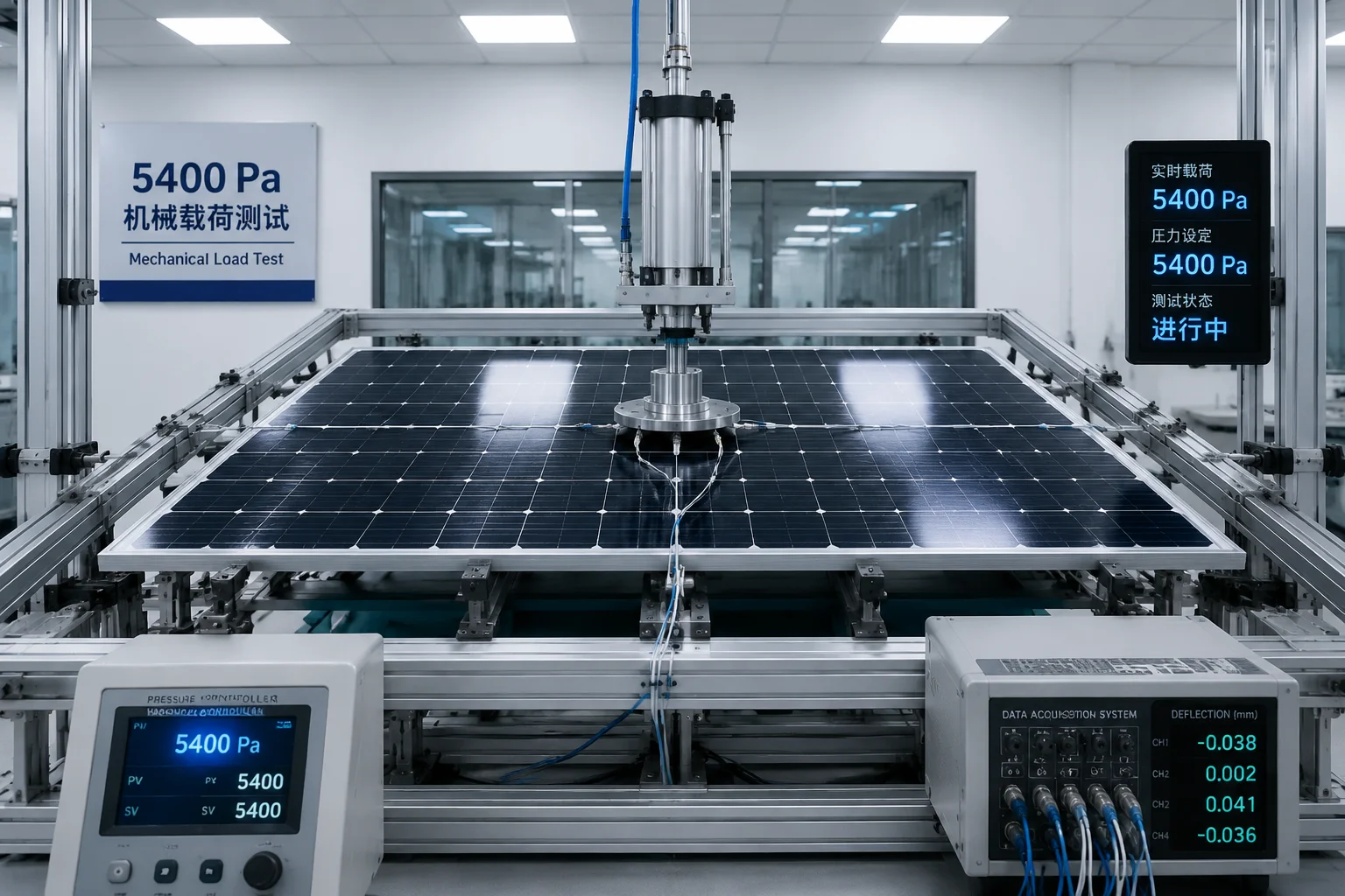
How Do You Test the “Mechanical Load” Capacity (e.g., 5400 Pa) of the Solar Mount?
I always ask manufacturers for their test certificates. Many can’t provide them. That’s a red flag that tells me their specs are made up.
Mechanical load testing applies uniform pressure to the panel surface using airbags or hydraulic systems while measuring deflection at multiple points. A panel rated for 5400 Pa must show less than 1% permanent deformation after one hour under load, verified by IEC 61215 standards.
 Mechanical load testing equipment with pressure sensors
The IEC 61215 Test Protocol
The International Electrotechnical Commission sets the standard for solar panel testing. The IEC 612153 protocol is what serious manufacturers follow.
The test works like this. You mount the panel on a rigid frame. Then you place a large airbag on top of the panel. You inflate the airbag to create uniform pressure across the entire surface.
For a 5400 Pa rating, you need to apply 5400 Newtons per square meter. On a typical 100-watt panel (about 1 square meter), that’s 5400 Newtons total. That’s equivalent to having 550 kilograms sitting on your panel.
Measurement Points and Deflection Limits
During the test, sensors measure how much the panel bends. The critical measurement is at the center of the panel. This is where maximum deflection occurs.
The panel must not bend more than a specific amount. The exact limit depends on panel size, but generally, the center deflection should stay under 5mm for a 1-meter panel.
After you release the pressure, you measure again. The panel should return to within 1% of its original shape. If it stays bent, the frame has permanently deformed. That’s a failure.
Front Load vs Back Load Testing
Panels face two types of wind pressure. Front load is when wind pushes directly on the panel face. Back load is when wind creates suction on the back side.
Front load testing typically uses higher pressures. A good panel handles 5400 Pa from the front. This simulates snow load and direct wind pressure.
Back load testing uses lower pressures, usually 2400 Pa. This simulates the suction effect when wind flows over the panel. Back load is actually more dangerous for the frame because it tries to pull the glass away from the frame.
Dynamic vs Static Load Testing
The basic test I described is static. You apply pressure and hold it. But real wind isn’t static. It gusts and fluctuates.
Advanced testing includes dynamic loads. The test equipment cycles the pressure on and off. It might apply 5400 Pa for 10 seconds, release for 5 seconds, then apply again. This cycle repeats 1000 times.
Dynamic testing reveals fatigue failures. A frame might survive one big wind event but fail after repeated smaller gusts. This is especially important in areas with frequent storms.
How to Verify Test Results
When a manufacturer claims 5400 Pa capacity, ask for the test report. The report should include:
- Name of the testing laboratory
- Date of the test
- Serial number of the tested panel
- Pressure applied and duration
- Deflection measurements at multiple points
- Photos or video of the test setup
- Pass/fail determination
If they can’t provide this documentation, assume the rating is fake. I’ve caught many suppliers claiming 5400 Pa when their panels were never tested at all.
Real-World Safety Factors
Even if a panel passes the 5400 Pa test, I don’t install it in locations where I expect 5400 Pa winds. I use a safety factor of at least 1.5.
If my wind calculations show 3600 Pa maximum expected load, I specify panels rated for 5400 Pa2. This gives me a 50% safety margin. This margin accounts for installation imperfections, frame aging, and unexpected wind patterns.
Here’s my selection guide:
| Expected Wind Condition | Minimum Required Rating | Recommended Frame Thickness |
|---|---|---|
| Category 1-2 Hurricane (up to 110 mph) | 3600 Pa | 35mm with internal ribs |
| Category 3 Hurricane (111-129 mph) | 4800 Pa | 40mm with dual-chamber design |
| Category 4-5 Hurricane (130+ mph) | 6000 Pa | 40mm+ with reinforced corners |
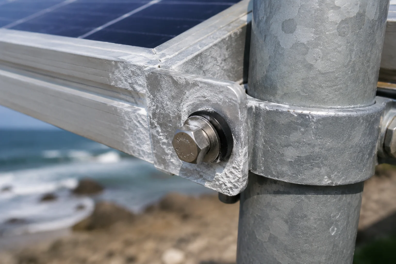
Will the Frame Undergo “Galvanic Corrosion” When Mounted on a Galvanized Steel Pole?
I’ve replaced dozens of panels where the aluminum frame corroded away at the mounting points. The panels still worked, but the frames were so weak they couldn’t hold the glass anymore.
Galvanic corrosion occurs when aluminum frames contact galvanized steel in the presence of moisture, creating a battery effect that dissolves the aluminum. Proper installation requires stainless steel hardware and insulating washers to prevent direct metal-to-metal contact between dissimilar metals.
 Galvanic corrosion damage on aluminum frame mounting point
Understanding the Galvanic Series
Different metals have different electrical potentials. When two dissimilar metals touch in the presence of an electrolyte (like rainwater), they form a battery. Current flows from one metal to the other.
The metal that loses electrons corrodes faster. This is called the anode. The metal that receives electrons is protected. This is called the cathode.
Aluminum is more anodic than zinc (the coating on galvanized steel). So when aluminum touches galvanized steel in wet conditions, the aluminum corrodes.
Why Coastal Installations Are Worse
Salt water is a much better electrolyte than fresh water. In coastal areas, the air contains salt particles. When these particles land on your mounting hardware, they create a conductive path between the aluminum and steel.
I’ve seen frames in coastal Florida corrode through in just three years. The same installation 50 miles inland might last 15 years before showing problems.
The corrosion starts at the mounting points because that’s where the metals touch. You’ll see white powder forming around the bolts. This powder is aluminum oxide. It’s the aluminum frame literally dissolving.
Proper Hardware Selection
The solution is to break the electrical connection between the aluminum and steel. You do this with proper hardware selection.
Use stainless steel bolts instead of galvanized steel. Stainless steel (especially 316 grade8) is much closer to aluminum on the galvanic series. The potential difference is smaller, so corrosion is much slower.
Add insulating washers between the frame and the mounting clamp. These washers are made from plastic or rubber. They physically separate the metals so no current can flow.
Some installers use anti-corrosion paste at the connection points. This paste contains zinc particles that act as a sacrificial anode7. The zinc corrodes instead of the aluminum.
Frame Design Features That Help
Better frames include built-in corrosion protection. Look for these features:
- Thicker anodization layer (20+ micrometers instead of the standard 15)
- Powder coating over the anodization at mounting points
- Stainless steel inserts molded into the frame at bolt holes
- Drainage channels that prevent water from pooling at connections
The stainless steel inserts are especially effective. The bolt contacts stainless steel instead of aluminum. Since both are relatively noble metals, galvanic corrosion is minimal.
Inspection and Maintenance Schedule
Even with proper installation, you should inspect mounting hardware annually in harsh environments. Look for:
- White powder around bolts (aluminum corrosion)
- Red/brown staining (steel corrosion)
- Loose connections (corrosion can eat away material and reduce clamping force)
- Cracks in the frame near mounting points
If you catch corrosion early, you can clean the area and add protective measures. If you wait too long, the frame loses structural integrity and you need to replace the entire panel.
Material Compatibility Chart
Here’s a quick reference for mounting hardware selection:
| Frame Material | Mounting Structure | Hardware Material | Insulation Required | Corrosion Risk |
|---|---|---|---|---|
| Anodized Aluminum | Galvanized Steel | Galvanized bolts | Yes | High |
| Anodized Aluminum | Galvanized Steel | Stainless steel bolts + washers | Yes | Low |
| Anodized Aluminum | Stainless Steel | Stainless steel bolts | No | Very Low |
| Anodized Aluminum | Aluminum | Stainless steel bolts | No | Very Low |
Can I Get a Structural Calculation Showing the Panel’s Safety Factor at 120 mph Winds?
I won’t install a system without running the numbers first. Too many installers just guess and hope for the best. That’s how panels end up in the next county after a storm.
Structural calculations convert wind speed to pressure load, apply safety factors per ASCE 7 standards, and verify that frame strength exceeds applied loads. For 120 mph winds (Category 3), the calculation shows approximately 3500 Pa pressure, requiring panels rated for at least 5250 Pa with a 1.5 safety factor.
 Engineering calculation sheet with wind load formulas
Converting Wind Speed to Pressure
Wind pressure increases with the square of velocity. This means doubling the wind speed quadruples the pressure.
The basic formula is: Pressure (Pa) = 0.613 × V² × Cd
Where V is wind speed in meters per second and Cd is the drag coefficient (typically 1.2 for flat panels).
For 120 mph winds:
- Convert to m/s: 120 mph = 53.6 m/s
- Calculate: 0.613 × (53.6)² × 1.2 = 2,110 Pa base pressure
But this is just the starting point. You need to apply several correction factors.
ASCE 7 Wind Load Factors
The American Society of Civil Engineers publishes ASCE 75, the standard for calculating wind loads on structures. It includes several factors that modify the base pressure.
Exposure category: Open terrain (Exposure C) has higher wind speeds than suburban areas (Exposure B). The factor ranges from 1.0 to 1.5.
Height factor: Wind speed increases with height above ground. A panel at 20 feet experiences more wind than one at 6 feet.
Gust factor: Steady wind is less damaging than gusting wind. The gust factor is typically 1.3 for small structures.
Importance factor: Critical infrastructure gets a higher safety factor. For security cameras, I use 1.15.
When you multiply all these factors, the 2,110 Pa base pressure becomes approximately 3,500 Pa actual design load.
Frame Strength Calculation
Now you need to verify the frame can handle this load. The frame’s strength depends on:
- Material properties (aluminum 6063-T5 has a yield strength of 145 MPa)
- Cross-sectional geometry (moment of inertia)
- Span length (distance between mounting points)
- Number of support points
For a typical 100W panel with a 40mm frame:
- Frame moment of inertia: approximately 8.5 cm⁴
- Span between supports: 80 cm
- Maximum bending stress at 3,500 Pa: approximately 95 MPa
Since 95 MPa is less than the 145 MPa yield strength6, the frame won’t permanently deform. But we need a safety factor.
Applying Safety Factors
I use a minimum safety factor of 1.5 for all permanent installations. For critical systems (hospitals, emergency shelters, security infrastructure), I increase this to 2.0.
The safety factor accounts for:
- Manufacturing variations (real frames are never perfect)
- Material degradation over 25+ years of service
- Installation errors (clamps not perfectly aligned)
- Extreme gusts exceeding the design wind speed
- Ice or debris adding unexpected weight
Here’s how the math works:
Required panel rating = Design wind load × Safety factor
For 120 mph winds: 3,500 Pa design load × 1.5 safety factor = 5,250 Pa minimum panel rating
This is why I don’t install 35mm frames rated for 3,600 Pa in hurricane zones. They might survive the first storm, but without margin for error, you’re gambling with your equipment.
Conclusion
The 35mm to 40mm aluminum frame thickness isn’t about what works in perfect conditions. It’s about what survives when everything goes wrong. I’ve seen 40mm frames hold panels flat on a roof while the neighbor’s 30mm frames turned into pretzels 200 feet away.
You’re not paying for the extra 5mm of aluminum. You’re paying for the margin of error that keeps your system running through the storm when you need it most. That’s a bargain at any price.
1. Understand how the moment of inertia quantifies resistance to bending in structural elements. ↩︎ 2. Reference for mechanical load testing pressure levels used in solar panel certification. ↩︎ 3. The international standard for crystalline silicon terrestrial photovoltaic modules, including mechanical load testing. ↩︎ 4. Learn about the electrochemical process that forms a protective oxide layer on aluminum. ↩︎ 5. The American Society of Civil Engineers standard for wind loads on structures, critical for engineering calculations. ↩︎ 6. Definition of yield strength and its role in ensuring structural components do not permanently deform under load. ↩︎ 7. Understand how a more reactive metal can be used to protect aluminum from galvanic corrosion. ↩︎ 8. Properties of 316 stainless steel, a corrosion-resistant grade ideal for marine environments. ↩︎