
I’ve seen too many solar PTZ projects fail because installers picked the wrong voltage. The camera works fine on the bench. But after running 50 feet of cable to a remote pole, it won’t even boot up. The problem? Voltage drop ate up all the power before it reached the device.
Choosing 24V over 12V cuts transmission loss to just 25% of what you’d get with 12V. This happens because doubling the voltage halves the current, and power loss follows the square of current (I²R). For a 50-foot cable run, 24V systems maintain stable voltage while 12V systems often fail to meet minimum device requirements.
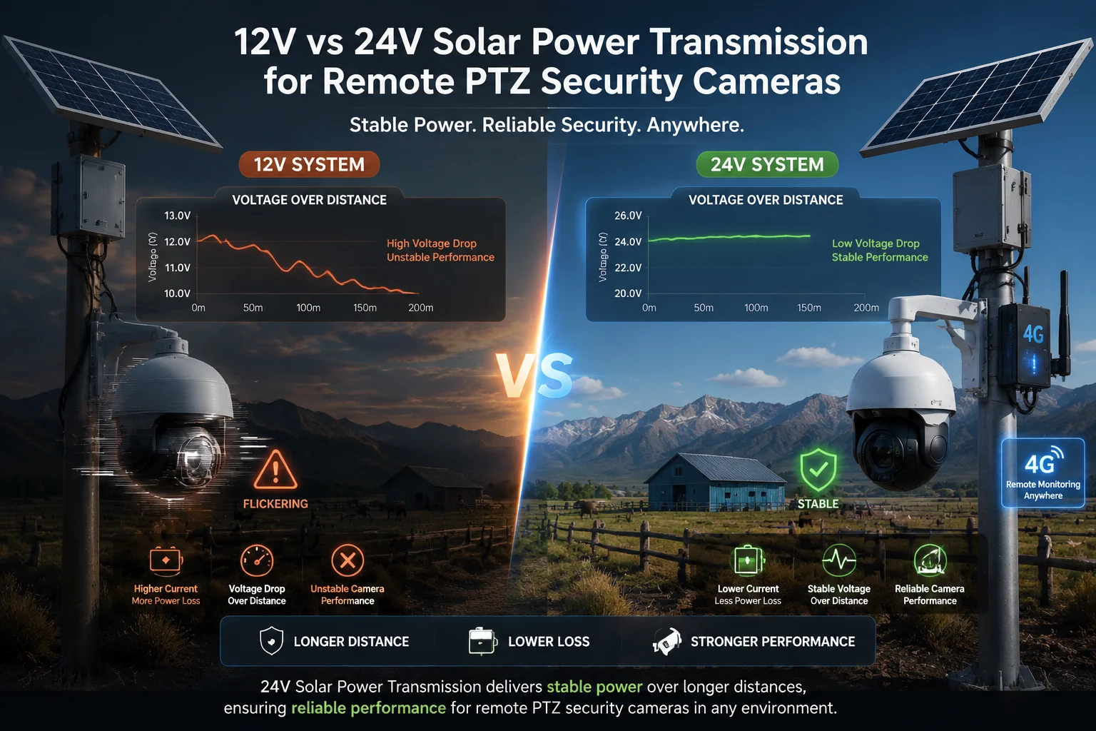 Solar PTZ camera voltage comparison 12V vs 24V transmission efficiency
If you’re installing multiple high-power PTZ cameras1 with 4G modules in off-grid locations, voltage selection isn’t just about efficiency. It’s about whether your system will work at all. Let me break down exactly how voltage affects your cable costs, system reliability, and long-term performance.
Table of Contents
Will a 24V System Significantly Reduce the “Voltage Drop” in My 50-Foot Power Cable?
I used to think voltage drop was just a minor annoyance. Then I watched a $15,000 project nearly collapse because the cameras kept rebooting. The client had four PTZ units spread across a farm, each one 15 meters from the solar panel. Every time a camera tried to zoom or activate its IR lights, the voltage would sag below 11V and the whole unit would crash.
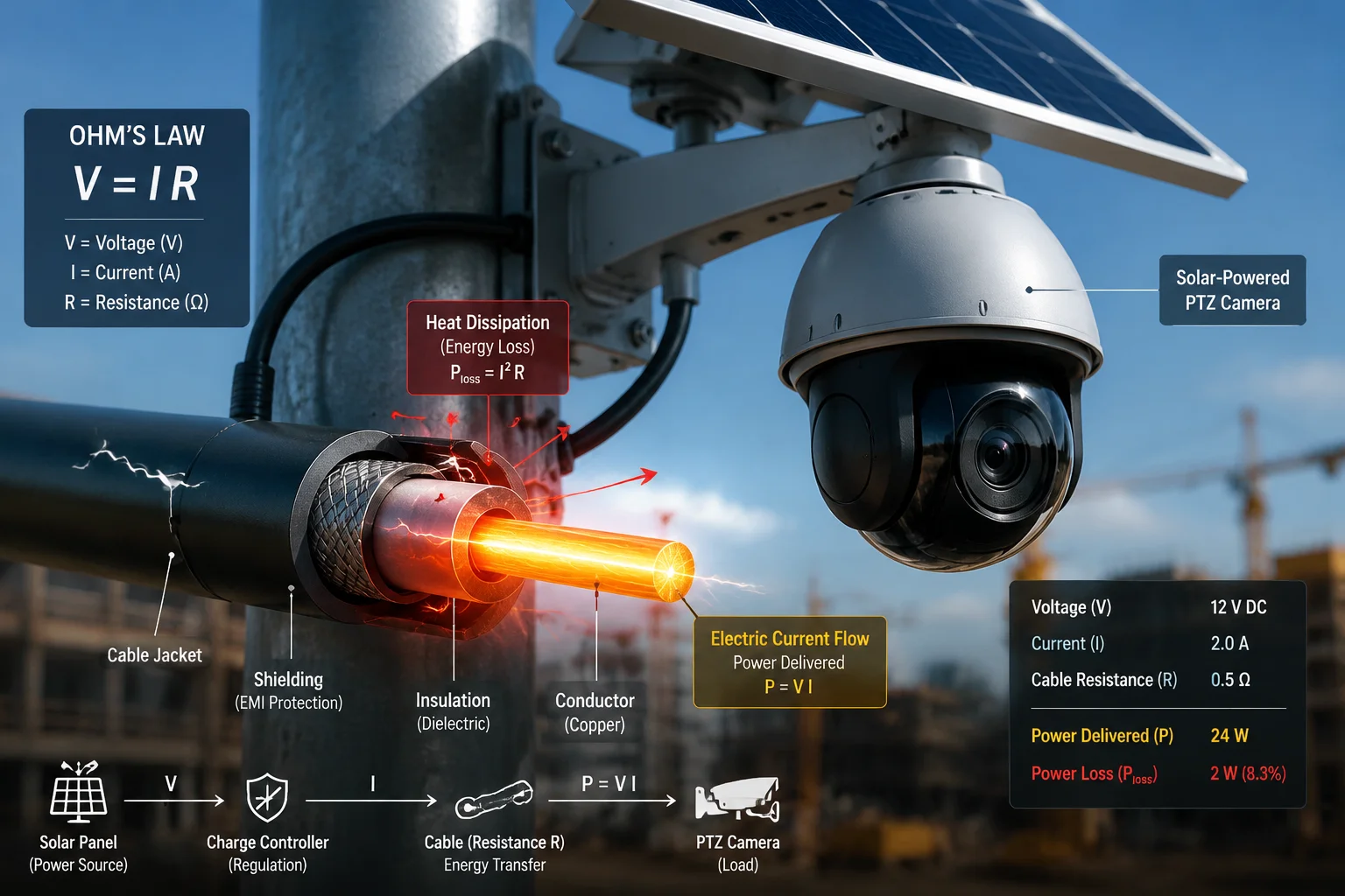
Yes, a 24V system reduces voltage drop by 75% compared to 12V for the same power load and cable size. When you double the voltage, you cut the current in half. Since voltage drop equals current times resistance (V=IR), halving the current directly halves the voltage drop. But power loss (heat) drops even more dramatically because it follows I²R.
 24V vs 12V voltage drop comparison chart long distance cable
The Physics Behind Voltage Drop
Voltage drop happens because every wire has resistance. When current flows through that resistance, some voltage gets “used up” heating the wire instead of powering your camera.
The formula is simple: Voltage Drop = Current × Resistance
Here’s what matters: resistance stays the same for a given wire. But current changes based on your system voltage.
If your PTZ camera draws 60W of power:
- At 12V: Current = 60W ÷ 12V = 5 amps
- At 24V: Current = 60W ÷ 24V = 2.5 amps
Now let’s say your 50-foot cable (round trip = 100 feet) has 0.5 ohms of resistance:
- At 12V: Voltage drop = 5A × 0.5Ω = 2.5V
- At 24V: Voltage drop = 2.5A × 0.5Ω = 1.25V
The 24V system loses half as much voltage. But here’s the critical part: your camera needs a minimum voltage to operate. Most PTZ cameras with 4G modules2 need at least 11V to boot up properly.
Real-World Impact on System Stability
Let’s use actual numbers from a typical solar PTZ installation:
| System Voltage | Cable Length | Wire Gauge | Current Draw | Voltage Drop | Voltage at Camera | Status |
|---|---|---|---|---|---|---|
| 12V | 50 feet | 14 AWG | 5A | 2.5V | 9.5V | Failed (below 11V minimum) |
| 12V | 50 feet | 10 AWG | 5A | 1.0V | 11.0V | Marginal (no safety margin) |
| 24V | 50 feet | 14 AWG | 2.5A | 1.25V | 22.75V | Excellent (large safety margin) |
| 24V | 50 feet | 16 AWG | 2.5A | 2.0V | 22.0V | Good (adequate margin) |
Notice something important: the 12V system with 14 AWG wire completely fails. You’d need to upgrade to 10 AWG wire (which costs 3x more and weighs twice as much) just to barely meet the minimum voltage requirement.
The 24V system works fine even with thinner 14 AWG wire. You could even use 16 AWG and still have plenty of voltage headroom.
Why Safety Margin Matters
PTZ cameras don’t draw constant power. When the camera pans, tilts, or activates IR illuminators, current spikes. A camera that normally draws 3A might briefly pull 6A during a fast pan movement.
With a 12V system running at the edge of its voltage tolerance, these current spikes cause the voltage to dip below the minimum threshold. The camera’s processor resets. The 4G module loses connection. You get random reboots that are nearly impossible to diagnose remotely.
A 24V system gives you breathing room. Even during peak current draw, you maintain enough voltage to keep everything stable.
Temperature Effects on Cable Resistance
Here’s something most installers forget: wire resistance increases with temperature. In direct sunlight, a black cable running up a pole can reach 60°C (140°F) or higher.
Copper resistance3 increases by about 0.4% per degree Celsius. A cable that’s 30°C hotter than room temperature will have roughly 12% more resistance. That 1.25V drop at 24V becomes 1.4V. Still acceptable. But that marginal 1.0V drop at 12V becomes 1.12V, pushing your camera below its operating threshold.
This is why 12V systems that work fine during cool mornings start failing in afternoon heat.
Can I Use Thinner, More Flexible Wires with a 24V Solar Setup to Save on Installation Costs?
I remember pricing out cable for a 20-camera project. The quote for 10 AWG copper came back at $2.80 per foot. For 4,000 feet of cable, that’s over $11,000 just for wire. The client asked if there was any way to cut that cost without compromising reliability.
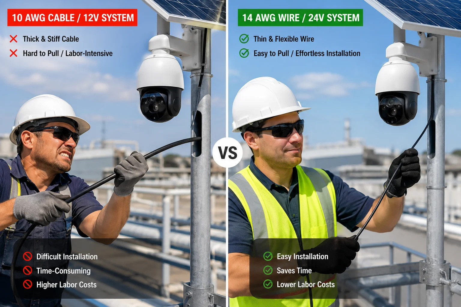
Yes, 24V systems allow you to use wire that’s 2-3 gauge sizes thinner than equivalent 12V systems while maintaining the same voltage drop percentage. This typically cuts cable costs by 40-60% and makes installation much easier because thinner wire is lighter and more flexible. For a 50-foot run carrying 60W, you can use 14 AWG at 24V instead of 10 AWG at 12V.
 Flexible thin gauge wire installation 24V solar PTZ system
Wire Gauge Economics
Wire cost increases exponentially as you go to thicker gauges. This happens because you’re buying more copper, and copper is expensive.
Here’s the price breakdown for common wire gauges (approximate costs for 2-conductor outdoor-rated cable):
| Wire Gauge | Cost per Foot | Weight per 100ft | Flexibility | Typical 12V Use | Typical 24V Use |
|---|---|---|---|---|---|
| 16 AWG | $0.45 | 3.2 lbs | Very flexible | Short runs only (<10ft) | Medium runs (up to 30ft) |
| 14 AWG | $0.70 | 5.1 lbs | Flexible | Short runs (up to 15ft) | Long runs (up to 60ft) |
| 12 AWG | $1.10 | 8.1 lbs | Moderate | Medium runs (up to 30ft) | Very long runs (100ft+) |
| 10 AWG | $2.80 | 12.8 lbs | Stiff | Long runs (up to 50ft) | Rarely needed |
| 8 AWG | $4.20 | 20.3 lbs | Very stiff | Very long runs (100ft+) | Rarely needed |
For that 50-foot run I mentioned earlier, switching from 10 AWG to 14 AWG saves you $2.10 per foot. Over 50 feet, that’s $105 per camera. With 20 cameras, you save $2,100 on cable alone.
Installation Labor Savings
Thinner wire doesn’t just cost less to buy. It costs less to install.
10 AWG wire is stiff and heavy. Running it through conduit requires two people. Making tight bends around corners often requires heat guns or special tools. Terminating thick wire into screw terminals takes more time and sometimes requires ferrules.
14 AWG wire is flexible enough for one person to handle. It feeds through conduit easily. It bends around corners without tools. It terminates quickly into standard screw terminals.
On a 20-camera project, the labor difference can be 2-3 hours per camera. At $75/hour for skilled installation labor, that’s another $3,000-$4,500 in savings.
Mechanical Advantages
Thinner wire has real practical benefits beyond cost:
Flexibility: 14 AWG wire can make tight 90-degree bends without kinking. This matters when routing cable through crowded junction boxes or around obstacles on a pole.
Weight: A 100-foot run of 10 AWG cable weighs nearly 13 pounds. The same length of 14 AWG weighs just 5 pounds. When you’re carrying cable up a 30-foot ladder, that difference matters.
Connector compatibility: Many solar charge controllers and camera terminals are designed for 14-16 AWG wire. Forcing 10 AWG wire into these terminals often requires adapters or custom crimping.
Conduit fill: Electrical codes limit how much wire you can run through a conduit4. Thinner wire means you can run more circuits through the same conduit, or use smaller (cheaper) conduit.
The Catch: You Still Need Proper Sizing
Switching to 24V doesn’t mean you can use any random thin wire. You still need to calculate voltage drop and ensure it stays within acceptable limits (typically 3% or less).
The rule of thumb: for the same voltage drop percentage, you can use wire with 4x the resistance at 24V compared to 12V. Since wire resistance roughly doubles for every 3 gauge sizes, this means you can go about 2-3 gauges thinner.
But you also need to check ampacity5 (current-carrying capacity). Even though 24V systems draw less current, you still need wire thick enough to handle that current safely without overheating. For most solar PTZ applications drawing 2-4 amps, 14 AWG is more than adequate.
When Thinner Wire Isn’t Appropriate
There are situations where you shouldn’t downsize wire even with 24V:
Very long runs (over 100 feet): Even at 24V, you’ll need thicker wire to keep voltage drop acceptable.
High-power loads (over 100W per camera): Cameras with large IR illuminators or heaters draw more current. Calculate your specific voltage drop.
Harsh environments: If your cable will be exposed to extreme heat, physical abuse, or rodents, thicker wire provides more durability.
Future expansion: If you might add more cameras or higher-power devices later, oversizing wire now is cheaper than replacing it later.
Is the Conversion Efficiency of the Camera Better When Supplied with 24V Instead of 12V?
I had a client who insisted on 24V because he’d read somewhere that “higher voltage is always more efficient.” He was half right. The transmission efficiency is definitely better. But what happens inside the camera itself? That’s where things get interesting.
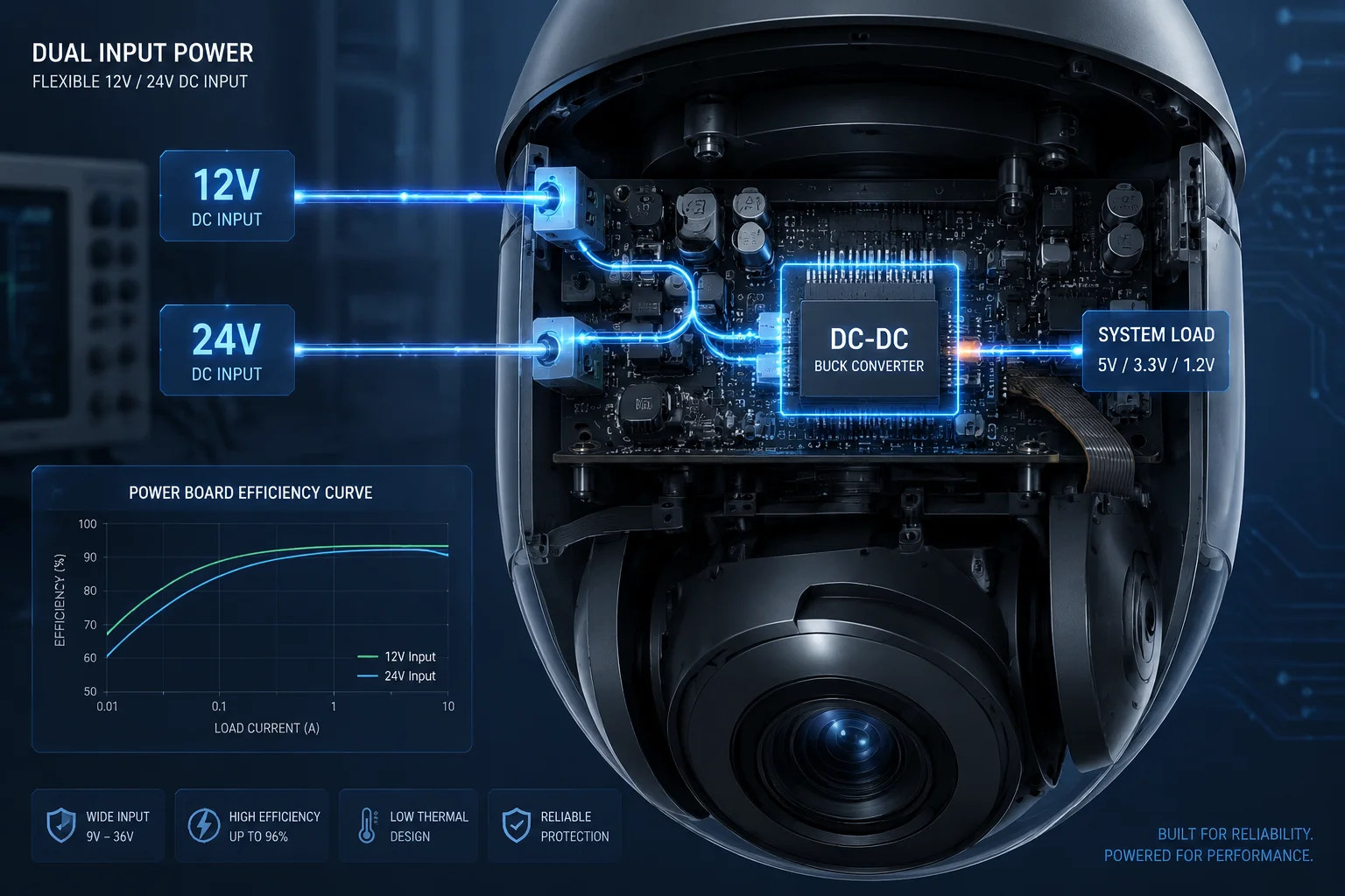
Camera internal conversion efficiency is typically 1-3% lower when supplied with 24V instead of 12V because the camera’s internal DC-DC converter must step down from a higher voltage. However, this small internal loss is completely overshadowed by the 50-75% reduction in cable transmission loss. The overall system efficiency is significantly better with 24V for any cable run over 10 feet.
 DC-DC buck converter efficiency curve 12V vs 24V input
How Camera Power Supplies Work
Modern PTZ cameras don’t run directly on 12V or 24V. Inside the camera housing, there are multiple voltage rails:
- Main processor: 5V or 3.3V
- Motor drivers: 12V
- IR LEDs: 3-5V (depending on series/parallel configuration)
- 4G module: 3.8V to 4.2V
- Image sensor: 1.8V to 3.3V
The camera uses DC-DC converters6 (usually buck converters) to step down the input voltage to these various levels. These converters are efficient, but not perfect. They lose some energy as heat.
Buck Converter Efficiency
A typical buck converter7 operates at 85-95% efficiency. The efficiency depends on several factors:
Input-to-output voltage ratio: Larger voltage drops generally mean slightly lower efficiency. Stepping 24V down to 5V is a bigger drop than stepping 12V down to 5V.
Load current: Converters are most efficient at 50-80% of their maximum rated current. At very light loads or very heavy loads, efficiency drops.
Switching frequency: Higher frequency converters can use smaller inductors but may have higher switching losses.
For a camera that needs 5V internally:
- 12V input: Buck converter steps down 7V (efficiency ~92%)
- 24V input: Buck converter steps down 19V (efficiency ~89%)
That 3% difference means a camera drawing 30W at the internal 5V rail will pull:
- At 12V input: 30W ÷ 0.92 = 32.6W from the 12V supply
- At 24V input: 30W ÷ 0.89 = 33.7W from the 24V supply
The 24V system wastes an extra 1.1W inside the camera. Over 24 hours, that’s 26 watt-hours of extra heat.
Why This Doesn’t Matter
That extra 1.1W of internal loss is completely irrelevant compared to cable losses.
Let’s use our earlier example: 50 feet of 14 AWG cable, 60W camera load.
12V system cable loss:
- Current: 5A
- Voltage drop: 2.5V
- Power loss: 5A × 2.5V = 12.5W
24V system cable loss:
- Current: 2.5A
- Voltage drop: 1.25V
- Power loss: 2.5A × 1.25V = 3.1W
The 24V system saves 9.4W in cable losses but wastes an extra 1.1W in internal conversion. Net savings: 8.3W.
That’s a 14% improvement in overall system efficiency. Over a 24-hour period, that’s 200 watt-hours saved per camera. With four cameras, you save 800 watt-hours per day. That’s the difference between needing a 200W solar panel versus a 150W panel.
Heat Management Considerations
The extra heat generated inside the camera housing from less efficient DC-DC conversion is usually not a problem. Camera housings are designed to dissipate 5-10W of heat through passive cooling (aluminum housing acting as a heatsink).
The bigger heat problem is actually in the cable itself. Remember that 12.5W of power loss in the 12V system? That heat is spread along 50 feet of cable. In direct sunlight, this can push cable temperature high enough to accelerate insulation degradation.
The 24V system’s 3.1W of cable loss generates much less heat, extending cable life.
When Internal Efficiency Actually Matters
There’s one scenario where camera internal efficiency becomes important: very short cable runs (under 5 feet) with high-power cameras.
If your cable loss is negligible (say, 0.5W), then that extra 1.1W of internal conversion loss actually matters. In this case, 12V might be slightly more efficient overall.
But this scenario is rare in solar PTZ installations. If your camera is only 5 feet from your solar panel and battery, you probably don’t need 4G connectivity or solar power in the first place. You’d just run AC power.
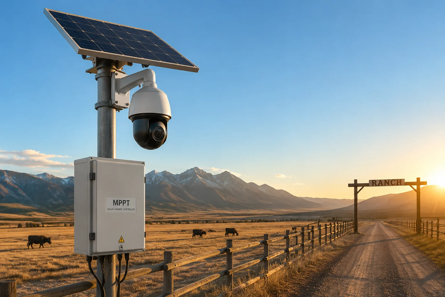
The Real Efficiency Winner: MPPT Charge Controllers
Here’s what actually matters for solar system efficiency: your charge controller.
A good MPPT8 (Maximum Power Point Tracking) charge controller operates at 96-98% efficiency regardless of whether it’s charging a 12V or 24V battery bank. The solar panel voltage is typically 18-22V for “12V” panels or 36-44V for “24V” panels.
Cheap PWM9 (Pulse Width Modulation) controllers waste 20-30% of your solar energy. Upgrading from PWM to MPPT saves far more energy than any difference between 12V and 24V camera input.
If you’re serious about efficiency, spend your money on a quality MPPT controller, not on worrying about whether your camera prefers 12V or 24V.
How Do I Choose Between 12V and 24V for a System with Four High-Power PTZ Cameras?
I just finished designing a system for a construction site with four PTZ cameras spread across 200 meters. Each camera had 40X optical zoom, 800-meter IR range, and a 4G module. The client’s first instinct was to use 12V because “that’s what car batteries use.” I had to walk him through why that would be a disaster.
For systems with four high-power PTZ cameras, choose 24V if any camera is more than 15 feet from the power source, if total system power exceeds 200W, or if you need to minimize cable costs. Choose 12V only if all cameras are within 10 feet of the battery bank and you need maximum compatibility with automotive accessories. For most professional installations, 24V is the clear winner.
 Four camera solar PTZ system 24V battery bank wiring diagram
Power Budget Analysis
High-power PTZ cameras with 4G modules and long-range IR can draw significant current. Let’s calculate a realistic power budget:
Per-camera power consumption:
- Idle (no movement, no IR): 8W
- Active pan/tilt: 15W
- IR illuminators at full power: 20-30W
- 4G module transmitting: 5-6W
- Heater (if equipped and active): 10-20W
That puts peak total per camera at 55-80W. For four cameras simultaneously active at night, that’s 220-320W total.
At 12V, peak current = 320W ÷ 12V = 26.7 amps
At 24V, peak current = 320W ÷ 24V = 13.3 amps
That 26.7A at 12V is severe. It requires 6 AWG or thicker cable for any run over 30 feet. The 24V system cuts the current in half, allowing 12-14 AWG for the same distance.
Conclusion
After designing dozens of solar PTZ systems, my rule is simple: If you need to run power cable more than 15 feet, use 24V.
The benefits are overwhelming:
- 75% reduction in transmission loss
- 40-60% lower cable costs (thinner, cheaper wire)
- Stable operation even during current spikes and high temperatures
- 50% lower battery bank current (less stress on batteries)
- Easy voltage conversion to 12V with a $20 DC-DC converter if needed
The only compelling reason to use 12V is very short distances or complete reliance on 12V-specific automotive components. For everyone else, 24V is the professional choice.
1. Overview of PTZ (pan-tilt-zoom) cameras and their applications. ↩︎ 2. Wikipedia page on 4G mobile broadband technology. ↩︎ 3. Explanation of electrical resistance in cables and how temperature affects it. ↩︎ 4. Guidelines for conduit fill calculations based on electrical codes. ↩︎ 5. Definition and explanation of ampacity (current-carrying capacity) of conductors. ↩︎ 6. General article on DC-DC converters and their types. ↩︎ 7. Wikipedia article on buck converters (step-down DC-DC converters). ↩︎ 8. Explanation of Maximum Power Point Tracking used in solar charge controllers. ↩︎ 9. Explanation of pulse-width modulation and its use in charge controllers. ↩︎