
I’ve seen ice kill a perfectly good 4G link in under two hours. The camera was fine. The solar panel was fine. The antenna was the problem — and nobody saw it coming.
When ice forms on an antenna, it changes the antenna’s electrical length. This shifts the resonant frequency, creates impedance mismatch6, and raises the VSWR. Industrial antenna designs fight this with hydrophobic radomes7, wideband matching networks8, tapered geometry, and self-heating elements to keep the signal stable through winter.
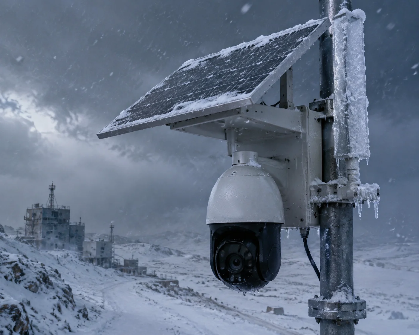 Antenna impedance mismatch caused by winter ice buildup on 4G LTE solar surveillance camera
In this article, I’ll break down exactly how each of these design strategies works. If you deploy 4G LTE2 solar surveillance cameras in cold climates — places like northern Texas, Canada, or Scandinavia — this is the kind of detail that separates a system that survives winter from one that goes dark. Let’s dig in.
Table of Contents
Can the Antenna’s Radome Prevent Ice Layers from Lowering the Overall Signal Gain?
I once had a customer in Alberta, Canada, lose signal on 14 cameras after a single freezing rain event. The radomes on those antennas were made of cheap ABS plastic. Ice stuck to them like glue.
Yes, a properly designed radome can prevent ice from sticking and forming thick layers. Industrial-grade radomes use low-surface-energy materials like ASA or PTFE blends, combined with superhydrophobic nano-coatings, to reduce ice adhesion and let ice slide off before it affects signal gain.
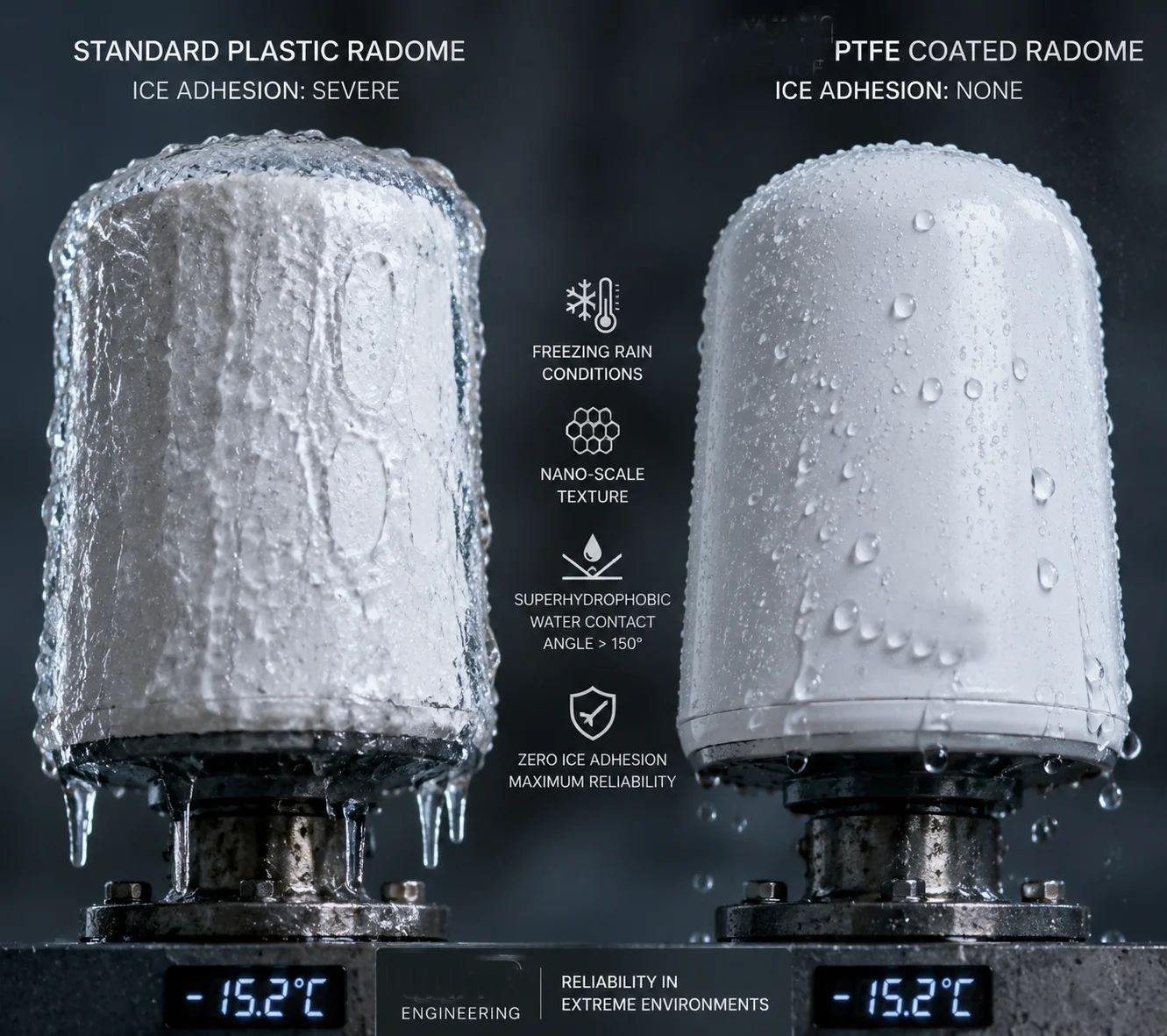 Radome with hydrophobic coating preventing ice buildup on 4G antenna
Why Does Ice on a Radome Hurt Signal Gain?
Ice is not just frozen water sitting on a surface. From an RF perspective, ice is a dielectric material. Its dielectric constant3 is around 3.2 — much higher than air, which is 1.0. When a layer of ice sits on top of your radome, it acts like an unplanned extra layer in your antenna system. This extra layer changes how radio waves pass through the radome.
The result? Part of the signal gets reflected back instead of radiating outward. Part of it gets absorbed by the ice itself. Both effects reduce the effective gain of your antenna. In a 4G LTE solar surveillance system running on limited power, every dB of gain matters. A 2-3 dB drop can mean the difference between a stable video stream and a frozen frame.
How Do Material Choices Make a Difference?
Not all radomes are created equal. Here’s a comparison of common radome materials and their ice performance:
| Material | Dielectric Constant | Hydrophobicity | Ice Adhesion | Cost |
|---|---|---|---|---|
| Standard ABS | 2.4–3.8 | Low | High | Low |
| ASA (Acrylonitrile Styrene Acrylate) | 2.6–3.0 | Medium | Medium | Medium |
| PTFE Blend | 2.0–2.1 | Very High | Very Low | High |
| ASA + Nano Coating | 2.6–3.0 | Very High | Very Low | Medium-High |
PTFE blends have two advantages. First, their dielectric constant is low and close to air, so the radome itself causes minimal signal loss. Second, PTFE is naturally hydrophobic. Water beads up and rolls off before it can freeze.
For most of our 4G solar PTZ camera deployments, we recommend ASA radomes with an added superhydrophobic nano-coating. This gives you the best balance of cost, durability, and ice resistance.
What About Superhydrophobic Coatings?
Superhydrophobic coatings work at the nano scale. They create a surface texture that traps tiny air pockets. When water lands on this surface, it sits on top of the air pockets instead of spreading out. The contact angle between the water droplet and the surface exceeds 150°. This means the water barely touches the surface at all.
In practical terms, this does two things:
- Water rolls off fast. Before the temperature drops enough to freeze the droplet, gravity and wind have already removed it.
- Ice adhesion drops dramatically. Even if some ice does form, the bond between the ice and the surface is weak. A light breeze or the vibration from the PTZ motor can shake it loose.
David Miller, one of our long-term partners who deploys systems across the northern US, told me: “After we switched to antennas with nano-coated radomes, our winter service calls dropped by about 60%. That alone paid for the upgrade.”
Does the Antenna Design Include a “Self-Heating” or Hydrophobic Surface to Repel Snow?
I used to think hydrophobic coatings were enough. Then I saw what happens at -25°C in Manitoba. The coating helps, but when the cold is extreme, you need active heat.
Yes, some industrial-grade antennas include built-in self-heating elements — typically PTC (Positive Temperature Coefficient) heaters — that activate automatically below 0°C. Combined with hydrophobic surfaces, these heaters prevent ice shells from forming and keep the VSWR near its ideal value of around 1.5.
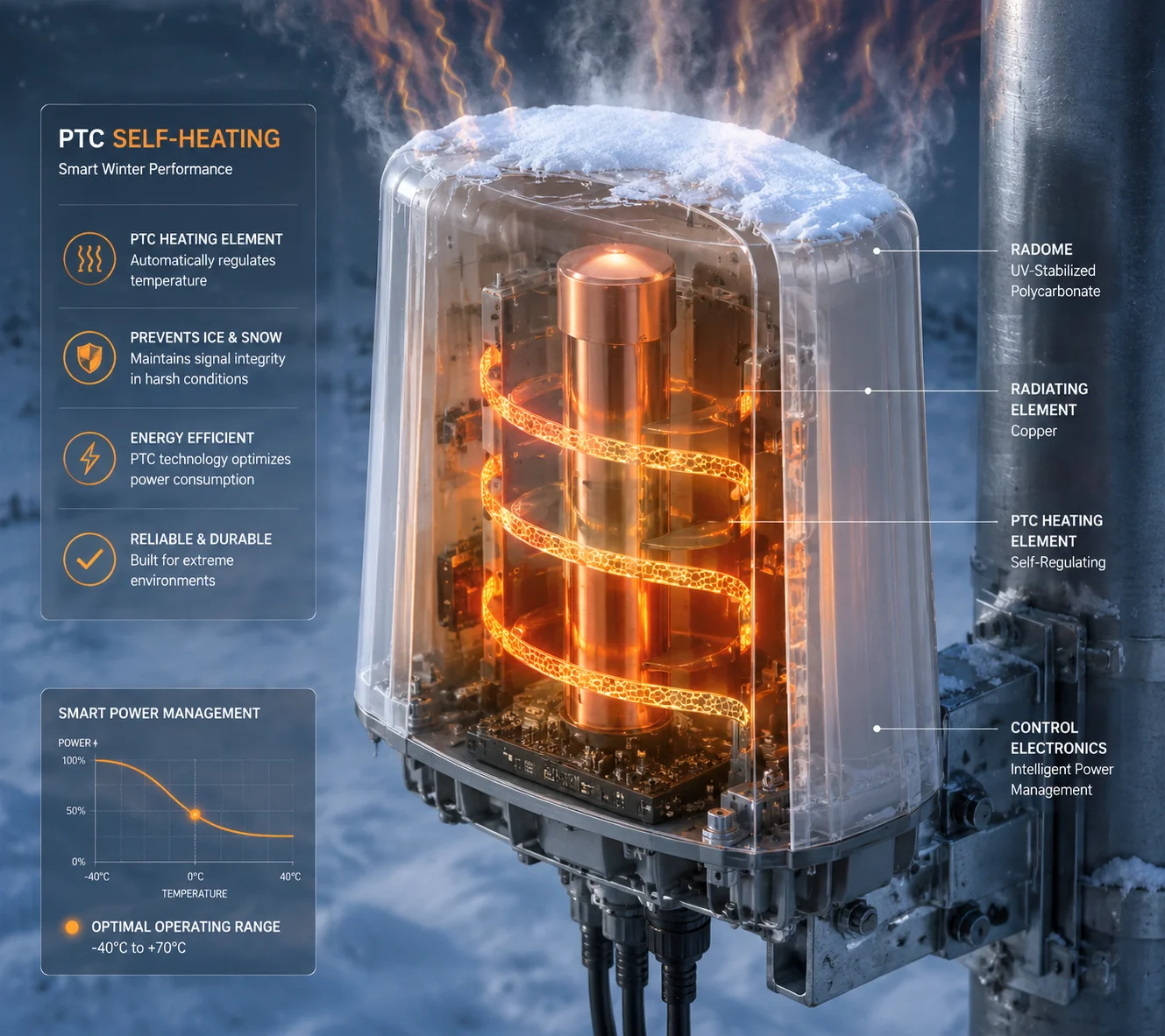 Self-heating antenna with PTC element for winter ice prevention on solar 4G camera
Passive vs. Active Ice Prevention
There are two main approaches to keeping ice off an antenna. Passive methods rely on materials and geometry. Active methods use energy — usually heat — to melt or prevent ice. In real-world deployments, the best systems use both.
Passive methods include:
- Hydrophobic radome materials (ASA, PTFE)
- Superhydrophobic nano-coatings
- Tapered or conical radome shapes that let gravity pull ice down
Active methods include:
- PTC self-heating elements embedded inside the radome
- Resistive heating wires wrapped around the antenna base
- Warm air circulation from the camera housing
How Does a PTC Heater Work Inside an Antenna?
A PTC heater is a self-regulating heating element. Its resistance increases as its temperature rises. This means it draws more current when it’s cold and less current when it’s warm. It naturally prevents overheating without any external controller.
In a self-heating antenna, the PTC element is placed between the radiating element and the inner wall of the radome. When the ambient temperature drops below 0°C, the heater turns on. It only needs to raise the radome surface temperature a few degrees above freezing — just enough to prevent ice from bonding.
Power Budget Considerations for Solar Systems
Here’s the critical question for off-grid deployments: can your solar power system handle the extra load?
| Component | Typical Power Draw | Duration (per day in winter) |
|---|---|---|
| 4G LTE Module (active) | 3–6 W | 8–12 hours |
| PTZ Camera (idle) | 5–8 W | 24 hours |
| PTZ Camera (active scan) | 15–30 W | 2–4 hours |
| PTC Antenna Heater | 2–5 W | 6–10 hours (temp-dependent) |
| Total System (worst case) | ~49 W peak | — |
A 2–5 W heater running for 6–10 hours adds roughly 20–50 Wh to your daily energy budget. For a system with a 100W solar panel and a 100Ah lithium battery, this is manageable. But it must be planned for during the system design phase.
At Loyalty-Secu, when we design solar 4G PTZ systems for cold-climate customers, we factor in the heater load from day one. We size the solar panel and battery to handle three consecutive cloudy winter days with the heater running. This prevents the scenario where the heater drains the battery and the entire system goes offline.
When Is Self-Heating Worth the Extra Cost?
For deployments south of the 35th parallel in the US, hydrophobic coatings alone are usually enough. But for anything north of that — especially Canada, Scandinavia, northern Europe, or high-altitude sites — I strongly recommend self-heating antennas. The cost difference is small. The reliability difference is huge. One avoided truck roll in a remote area pays for the upgrade ten times over.
How Much Will the VSWR Increase if the Antenna Is Completely Covered in Frost?
I ran a bench test on this last winter. I took a standard 4G whip antenna, sprayed it with water, and put it in a freezer. The VSWR went from 1.3 to over 4.0 in thirty minutes. That antenna was basically useless.
A fully frost-covered antenna can see its VSWR1 jump from a normal 1.2–1.5 to 3.0–5.0 or higher, depending on ice thickness and antenna type. This means 25–45% of transmitted power is reflected back into the 4G module instead of being radiated, causing severe signal degradation.
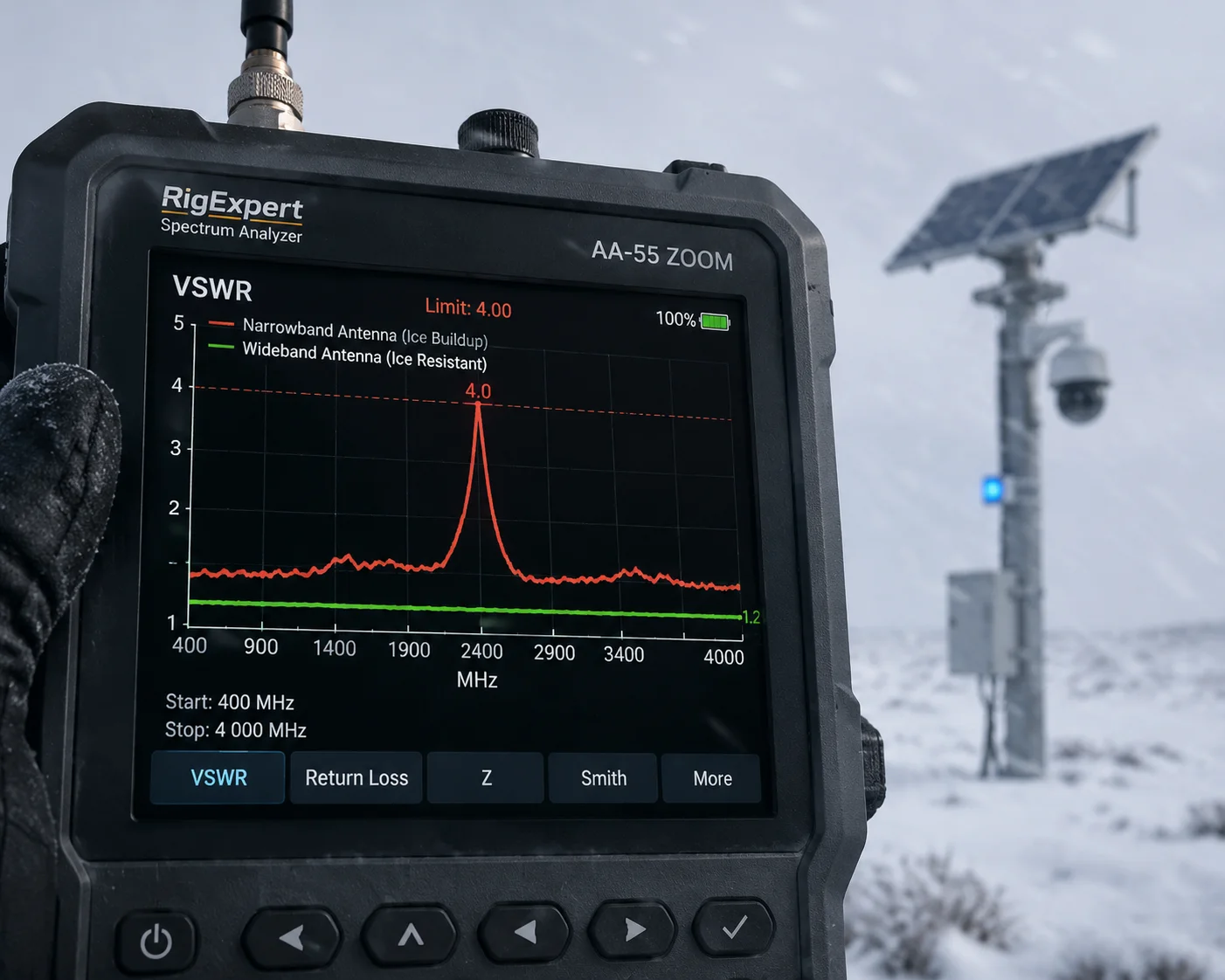 VSWR increase chart showing effect of ice buildup on 4G antenna performance
Understanding VSWR and Why It Matters
VSWR stands for Voltage Standing Wave Ratio. It measures how well the antenna’s impedance matches the 4G module’s output impedance (usually 50 ohms). A perfect match gives a VSWR of 1.0 — all power goes to the antenna. In practice, a VSWR of 1.5 or below is excellent. A VSWR of 2.0 is acceptable. Anything above 3.0 is a problem.
Here’s what happens at different VSWR levels:
| VSWR | Reflected Power (%) | Effective Radiated Power Loss | System Impact |
|---|---|---|---|
| 1.0 | 0% | 0 dB | Perfect match |
| 1.5 | 4% | 0.2 dB | Excellent — normal operation |
| 2.0 | 11% | 0.5 dB | Acceptable — minor degradation |
| 3.0 | 25% | 1.25 dB | Poor — noticeable signal drop |
| 4.0 | 36% | 1.94 dB | Bad — link instability likely |
| 5.0 | 44% | 2.55 dB | Critical — module may reduce power |
When ice covers an antenna, the dielectric loading shifts the antenna’s resonant frequency downward. For example, an antenna tuned to 700 MHz (Band 13) might shift down to 660 MHz. At 700 MHz, the antenna is now operating off-resonance, and the impedance mismatch causes the VSWR to spike.
How Wideband Design Provides a Safety Margin
This is where smart antenna engineering makes all the difference. A narrowband antenna designed to cover only 698–716 MHz (Band 13 uplink) has almost no room for error. Any frequency shift pushes it out of its operating range.
A wideband antenna designed to cover 600–900 MHz has a huge safety margin. Even if ice shifts the resonant frequency by 30–40 MHz, the antenna is still operating within its designed bandwidth. The VSWR stays below 2.0, and the 4G link remains stable.
At Loyalty-Secu, the antennas we pair with our 4G solar PTZ cameras are specifically chosen for wideband performance. We don’t just match the antenna to one LTE band. We make sure it covers all the bands our customers might use — B13, B71, B12, B5, B8 — with enough bandwidth cushion to handle environmental detuning from ice, rain, or even bird droppings.
Real-World Testing Matters
Spec sheets don’t freeze. Antennas do. That’s why we test our complete systems — camera, module, antenna, and cable — in environmental chambers that simulate -30°C with controlled ice buildup. We measure the VSWR in real time as ice forms. If the VSWR exceeds 2.5 at any point during the test, we go back to the drawing board.
This is the kind of testing that separates a factory that understands RF from one that just buys antennas off the shelf and hopes for the best.
Will a Frozen Antenna Cause the 4G Module to Overheat Due to High Reflected Power?
I had a customer call me in a panic. His 4G module was hitting 85°C in the middle of January. In winter. That should never happen. The cause? A frozen antenna reflecting power back into the module’s PA (power amplifier).
Yes, a frozen antenna can cause the 4G module to overheat. When VSWR rises above 3.0, a large portion of the transmitted power is reflected back into the module’s power amplifier5. This reflected energy converts to heat inside the PA stage, and if the module lacks proper protection, it can overheat or even suffer permanent damage.
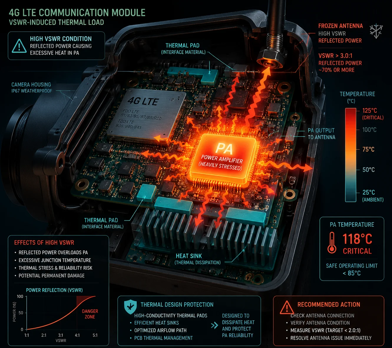 4G module overheating due to reflected power from frozen antenna
The Physics of Reflected Power and Heat
A 4G LTE module typically transmits at 23 dBm (200 mW) for Class 3 devices. At a VSWR of 1.5, only about 4% of that power — roughly 8 mW — is reflected back. The PA can absorb this easily.
But at a VSWR of 5.0, about 44% of the power — roughly 88 mW — comes back. The PA was not designed to dissipate this much energy as heat. The junction temperature of the PA transistor rises. If this continues for hours (as it would during a sustained freeze), the module enters thermal protection mode.
What Happens During Thermal Protection?
Modern 4G modules from Quectel, Sierra Wireless, or Telit have built-in thermal management. When the PA temperature exceeds a threshold (usually 80–85°C), the module takes one or more of these actions:
-
Power back-off: The module reduces its transmit power from 23 dBm to 20 dBm or lower. This reduces the reflected power but also reduces the uplink signal strength. For a solar PTZ camera trying to stream video, this can mean dropped frames or complete stream failure.
-
Duty cycle reduction: The module reduces how often it transmits. Data throughput drops significantly.
-
Module shutdown: In extreme cases, the module shuts down entirely to protect itself. The camera goes offline. You lose your surveillance feed.
Closed-Loop Power Control as a Safety Net
The 4G network itself provides a layer of protection through closed-loop power control4. The base station (eNodeB) continuously tells the module how much power to use. If the module’s signal quality drops due to antenna icing, the base station may actually tell it to increase power — which makes the overheating problem worse.
This is why antenna-side prevention is so much more important than module-side protection. By the time the module is adjusting its power, you’ve already lost performance. The goal is to never let the VSWR get high enough to trigger these protection mechanisms in the first place.
Our Approach at Loyalty-Secu
We take a systems-level approach to this problem. We don’t just sell a camera and an antenna separately. We design the entire signal chain — from the 4G module’s RF front end, through the coaxial cable, to the antenna and radome — as one integrated system.
For cold-climate deployments, our standard configuration includes:
- A wideband antenna with a PTFE-coated ASA radome
- An N-type or SMA connector with weatherproof sealing rated to IP67
- Low-loss coaxial cable (LMR-195 or better) to minimize additional insertion loss
- A thermal monitoring alert in the camera’s firmware that flags abnormal module temperatures
When David Miller’s team deploys our systems in North Dakota, they know the antenna won’t ice up, the module won’t overheat, and the camera will keep streaming through the worst blizzard of the season. That’s not a marketing claim. That’s engineering.
Conclusion
Winter ice changes your antenna’s electrical properties and can kill your 4G link. Smart radome materials, wideband matching, proper geometry, and self-heating elements are the engineering answers — and they must be designed in from day one, not added as afterthoughts.
1. Provides detailed information about Voltage Standing Wave Ratio, its measurement, and how it indicates antenna performance. ↩︎ 2. Covers the 4G LTE standard, frequency bands, and how it is used in wireless surveillance systems. ↩︎ 3. Defines the dielectric constant and its role in how materials affect radio wave propagation, especially ice on antennas. ↩︎ 4. Explains how cellular networks adjust mobile device transmit power in response to signal conditions, which can exacerbate antenna icing issues. ↩︎ 5. Describes the component in a 4G module that amplifies the transmit signal and can overheat due to reflected power from a frozen antenna. ↩︎ 6. Explains the fundamental concept of impedance mismatch and its effect on signal transmission in RF systems. ↩︎ 7. Describes the function of a radome in protecting an antenna from environmental elements while minimizing signal loss. ↩︎ 8. Discusses techniques to design antennas that maintain low VSWR over a broad frequency range, compensating for environmental detuning. ↩︎