
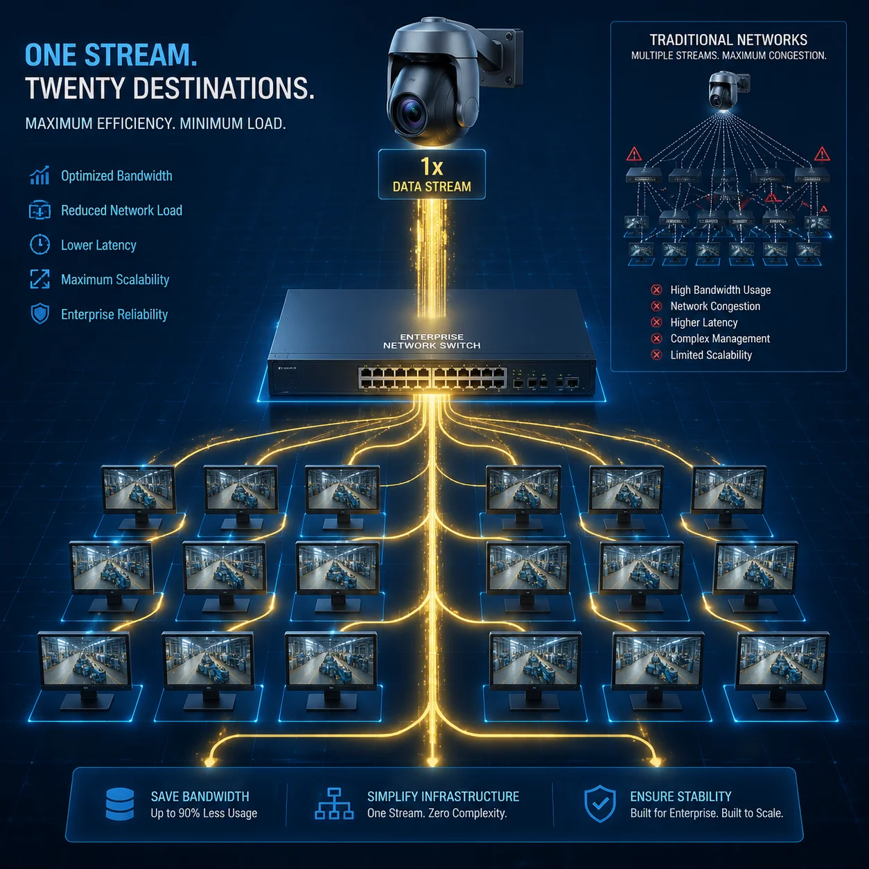
I have seen networks crash because 20 monitors pulled the same 4K stream1 through unicast. It is painful, expensive, and 100% avoidable.
Yes, our industrial-grade PTZ cameras fully support Multicast (IGMP v2/v3). In a large LAN where multiple clients need the same H.265 stream at the same time, the camera sends only one copy of the video. The network switches then replicate that single stream to each viewer. This drops your backbone bandwidth from N × Bitrate down to 1 × Bitrate, no matter how many screens are watching.
 PTZ camera multicast bandwidth optimization in large LAN
Below, I will walk you through the most common questions I get from system integrators and CTOs about Multicast deployment. Each answer comes from real project experience, not a datasheet copy-paste. If you are planning a multi-station monitoring setup, a factory-wide surveillance network, or a cross-VLAN campus project, keep reading.
Table of Contents
How Many Concurrent Clients Can View a Single 4K Stream Using Multicast on My Network?
Every time I quote “unlimited viewers, same bandwidth,” people think I am exaggerating. I am not. But there is a catch most vendors will not tell you.
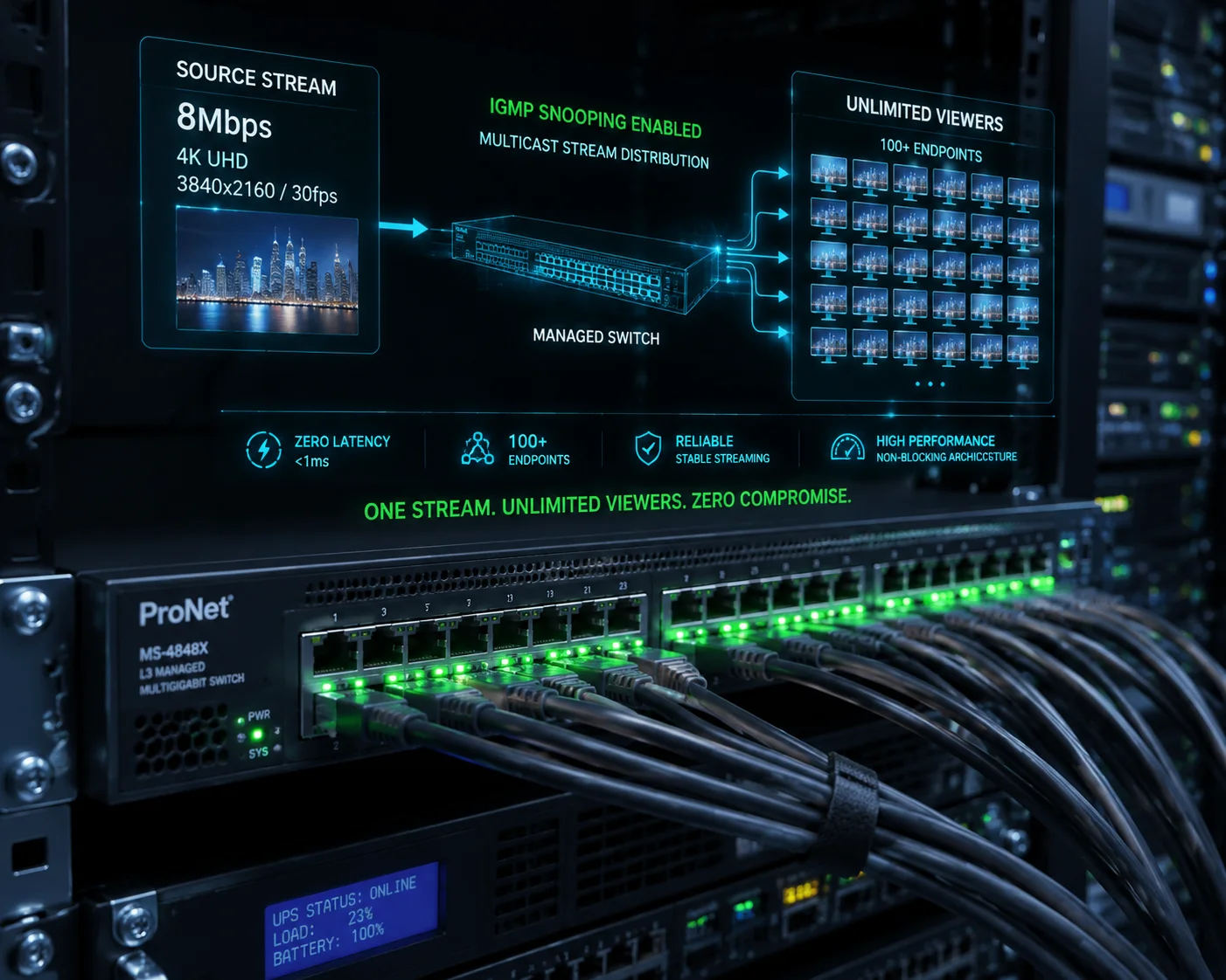
With Multicast enabled, the number of concurrent clients viewing a single 4K stream is not limited by the camera. It is limited by your switch fabric and IGMP snooping capacity. In practice, a properly configured managed switch can serve 50, 100, or even 200+ endpoints from one 8Mbps stream without adding any extra load to the camera’s uplink port.
 Multicast concurrent clients 4K stream network switch
Why the Camera Is No Longer the Bottleneck
In a unicast3 setup, the camera’s CPU and network interface must generate a separate RTP session8 for every single viewer. I have tested this on many cameras in our lab. Most PTZ cameras start dropping frames after 8–10 simultaneous unicast connections. Some cheaper models freeze at 5. The camera simply runs out of processing power.
With Multicast, the camera creates one IGMP group stream. That is it. One stream leaves the camera’s Ethernet port. The replication work shifts entirely to the network infrastructure.
Where the Real Limit Lives
The actual ceiling depends on three things in your network:
| Factor | What It Controls | Typical Limit |
|---|---|---|
| Switch backplane bandwidth | Total data the switch can move internally | 48–256 Gbps on enterprise switches |
| IGMP snooping table size | How many multicast groups and members the switch can track | 1,000–8,000 entries on Cisco Catalyst series |
| Uplink port speed | The pipe between your access switch and core switch | 1 Gbps or 10 Gbps |
So if your 4K H.265 stream runs at 8 Mbps, and your uplink is 1 Gbps, the math is simple. The uplink can carry 125 copies of that stream. But with Multicast, it only carries one copy on that uplink. The access switch at the viewer’s side does the replication locally.
A Real-World Number
In a recent factory project, one of our partners in Europe connected 64 monitoring workstations to a single 4K PTZ stream. The camera’s uplink port stayed at a flat 8 Mbps. CPU usage on the camera stayed below 30%. No frame drops. No latency spikes. The key was that every switch in the path had IGMP snooping turned on.
What Happens Without IGMP Snooping
If you skip IGMP snooping, the switch treats the multicast stream like a broadcast. Every port on every switch gets the video data. Your printers, your VoIP phones, your access control panels — they all receive 8 Mbps of video they never asked for. I have seen this bring down an entire office network in under 10 minutes. So the answer to “how many clients” is really “as many as your switches can handle,” but only if your switches are configured correctly.
Will Multicast Help Prevent Network Congestion When Streaming to Multiple Security Stations?
I talk to integrators every week who blame the camera for choppy video. Nine times out of ten, the problem is not the camera. It is the network architecture.
Multicast is the single most effective method to prevent network congestion when multiple security stations view the same camera feed. Instead of the camera sending duplicate streams to each station, it sends one stream, and the network delivers it efficiently. This eliminates the multiplicative bandwidth problem that causes congestion, packet loss, and frozen video.
 Multicast prevent network congestion security stations
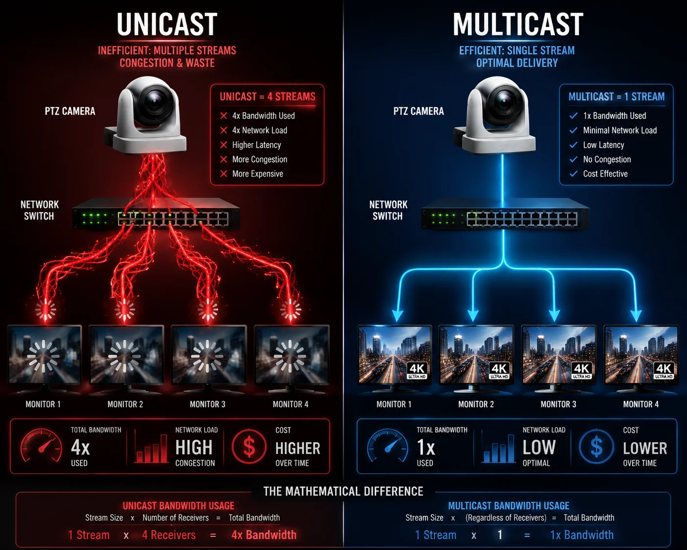
The Congestion Math: Unicast vs. Multicast
Let me put real numbers on this. Say you have a control room with 16 monitors, and each monitor displays a different camera. But 4 of those monitors show the same PTZ camera — maybe a gate entrance or a critical perimeter view.
Unicast scenario:
- Camera sends 4 separate streams at 6 Mbps each.
- Camera uplink usage: 24 Mbps.
- Core switch must route 4 independent flows.
- If 3 more stations in a second building also want that stream, the camera now pushes 42 Mbps for one single view.
Multicast scenario:
- Camera sends 1 stream at 6 Mbps.
- Every switch along the path carries only 6 Mbps for that camera, regardless of how many endpoints subscribe.
- Camera CPU stays idle. Uplink stays clean.
The Congestion Points Most People Miss
Network congestion does not always happen where you expect. Here are the three most common choke points I see in large surveillance LANs:
| Choke Point | Why It Gets Congested | How Multicast Fixes It |
|---|---|---|
| Camera uplink port | Multiple unicast sessions saturate the 100 Mbps port | Only one stream leaves the camera |
| Core switch uplink | Aggregated traffic from dozens of cameras overwhelms the trunk | Multicast traffic is replicated at the edge, not the core |
| Wireless bridge link | Limited throughput (often 50–100 Mbps effective) shared by all traffic | One copy crosses the bridge; local switch replicates |
Special Note for Solar 4G Off-Grid Projects
David, I know many of your projects involve our 4G solar PTZ systems deployed in remote areas. Here is the honest truth: standard 4G/5G public networks do not support Multicast. Mobile carriers block IGMP traffic on their infrastructure. So if your remote camera sends video over 4G to a cloud VMS, Multicast will not help on that WAN segment.
However, if you set up a local wireless bridge network between multiple poles on a job site — say a construction site with 5 camera poles and a site office — then Multicast becomes very useful. The Wireless bridge7 only carries one copy of each stream. The switch in the site office replicates it to the foreman’s laptop, the safety officer’s monitor, and the NVR. This setup can cut your wireless bridge load by 60–70%.
IGMP Snooping: The Non-Negotiable Requirement
I cannot stress this enough. Without IGMP snooping2 enabled on every switch in the path, Multicast traffic floods every port. This is worse than unicast because now every device on the VLAN receives the video stream. The result is a broadcast storm. I always tell our partners: before you enable Multicast on the camera, confirm IGMP snooping is active on your switches. Check the switch management interface. Look for the IGMP snooping status under the VLAN settings. If it says “disabled,” fix that first.
Is the Multicast Implementation Compatible with Standard Cisco or Juniper Layer-3 Switches?
I get this question a lot from North American integrators. They run Cisco or Juniper in every rack, and they need a straight answer before they spec our cameras into a bid.
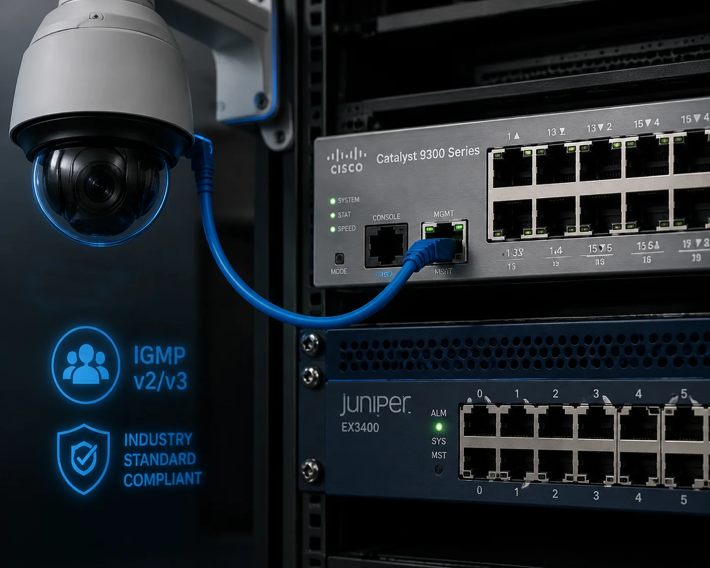
Our PTZ cameras use standard IGMP v2 and IGMP v3 protocols for Multicast. This means they are fully compatible with any managed switch that supports IGMP snooping, including Cisco Catalyst, Cisco Nexus, Juniper EX series, HPE Aruba, and H3C. There is no proprietary protocol involved. If your switch speaks IGMP, it works with our camera.
 Multicast compatible Cisco Juniper layer 3 switches IGMP
Why Standards Matter More Than Brand Names
Some camera manufacturers use proprietary streaming methods that only work with their own NVRs or their own software. That locks you into one ecosystem. Our cameras follow ONVIF Profile T4, which defines exactly how Multicast should be configured and discovered. Any ONVIF-compliant VMS — Milestone, Genetec, Blue Iris, Digifort — can automatically detect the Multicast group address and start receiving the stream.
IGMP Version Compatibility
There are two versions of IGMP that matter in practice:
- IGMP v2: The most widely deployed version. Supports basic join and leave messages. Works on almost every managed switch made in the last 15 years.
- IGMP v3: Adds source-specific multicast (SSM). This lets the switch filter traffic not just by group address but also by source IP. Useful in very large networks where multiple cameras might use the same group address range.
Our cameras support both. The camera defaults to IGMP v2 for maximum compatibility. You can switch to v3 in the web interface if your network requires it.
Tested Switch Platforms
I want to be specific here because vague compatibility claims waste everyone’s time. Our engineering team has tested Multicast streaming on the following platforms:
| Switch Platform | IGMP Snooping | Multicast Routing | Test Result |
|---|---|---|---|
| Cisco Catalyst 2960/3560/3850 | Supported | Supported (L3 models) | ✅ Full compatibility |
| Cisco Nexus 3000/5000 | Supported | Supported | ✅ Full compatibility |
| Juniper EX2300/EX3400 | Supported | Supported | ✅ Full compatibility |
| HPE Aruba 2530/2930 | Supported | Supported (2930) | ✅ Full compatibility |
| H3C S5130/S5560 | Supported | Supported | ✅ Full compatibility |
| TP-Link TL-SG3428 | Supported | Limited | ✅ Works for single VLAN |
What About Unmanaged Switches?
Unmanaged switches do not support IGMP snooping. If you plug our camera into a cheap unmanaged switch and enable Multicast, the switch will flood the stream to all ports. This defeats the entire purpose. For any project where Multicast matters, you need managed switches. This is not a camera limitation. It is a fundamental network requirement.
Cross-Vendor Interoperability in Practice
One of our partners in the Middle East runs a mixed network: Cisco core switches, H3C distribution switches, and TP-Link access switches. They enabled Multicast on 24 of our PTZ cameras. Every switch handled the IGMP joins correctly. The video played smoothly on all 40+ workstations. The only issue they hit was a TP-Link switch that had IGMP snooping disabled by default. Once they turned it on, everything worked. The lesson: check every switch in the path, not just the core.
Can I Set a Unique Multicast Group IP and TTL (Time to Live) for My Cross-VLAN Project?
Cross-VLAN multicast is where most projects get complicated. I have helped dozens of integrators troubleshoot this exact scenario, and the answer starts with proper camera-side configuration.
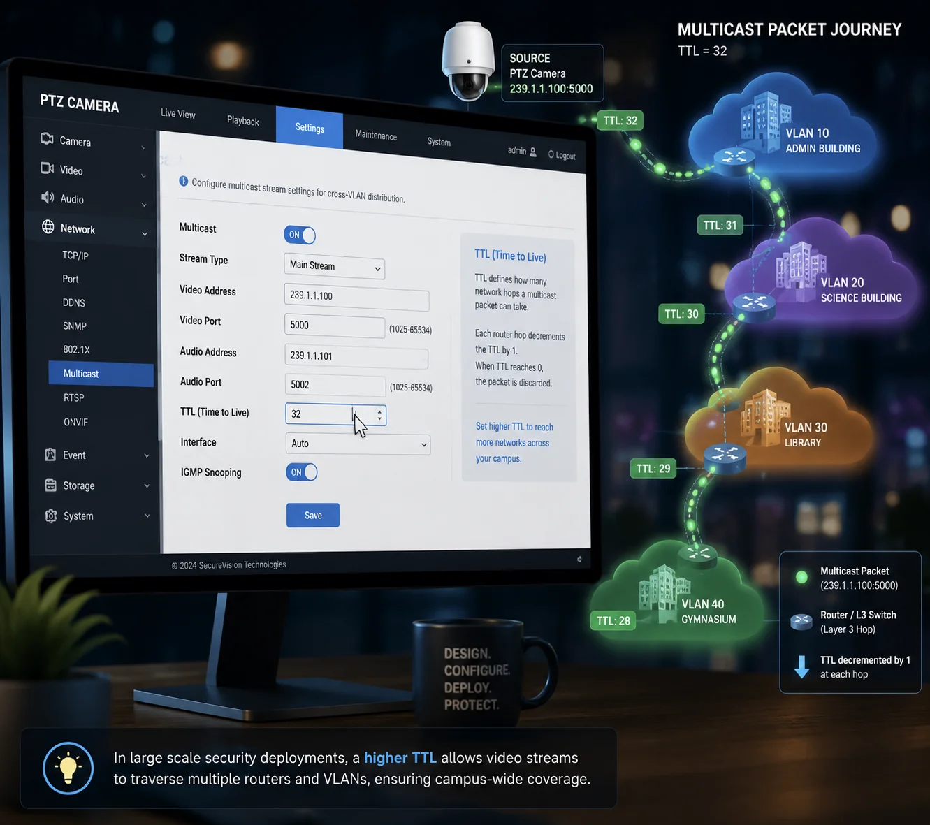
Yes, you can configure a custom Multicast group IP address and TTL value directly in the camera’s web interface. The group IP can be any valid Class D address between 224.0.0.0 and 239.255.255.255. The TTL can be set from 1 to 255, controlling how many router hops the stream can cross. For cross-VLAN deployments, set the TTL to at least 16 to ensure the stream passes through your layer-3 routing boundaries.
 Multicast group IP TTL cross VLAN configuration PTZ camera
Understanding the Multicast Address and Why It Matters
A Multicast group IP is not like a regular IP address. It does not belong to any single device. It is a “channel” that any device can subscribe to. Think of it like a radio frequency. The camera broadcasts on a specific channel, and any client that tunes in receives the stream.
Our cameras let you configure separate Multicast addresses and ports for three data types:
- Video stream: The main H.265 or H.264 video feed.
- Audio stream: Two-way or one-way audio, if your project requires it.
- Metadata stream: AI analytics results, such as human detection bounding boxes, license plate data, or motion event triggers.
This separation is important. Some VMS platforms subscribe only to the video Multicast group. Others need the metadata group to display AI overlays. By assigning different group addresses, you keep the traffic organized and give your VMS granular control over what it receives.
TTL: The Cross-VLAN Key
TTL stands for Time to Live. Every time a Multicast packet crosses a layer-3 boundary (a router or a layer-3 switch doing inter-VLAN routing), the TTL decreases by 1. When it reaches 0, the packet is dropped.
- TTL = 1: The stream stays within the local subnet. It will not cross any router. Good for single-VLAN setups.
- TTL = 16: The stream can cross up to 16 routing hops. This is enough for most campus networks with multiple VLANs.
- TTL = 32: Safe for very large enterprise networks with complex routing topologies.
- TTL = 128 or 255: Only needed for multi-site WAN Multicast, which is rare in surveillance.
I usually recommend TTL = 32 as a safe default for cross-VLAN projects. It gives you enough headroom without creating unnecessary traffic leakage into distant network segments.
Cross-VLAN Multicast: The Network Side
Setting the TTL on the camera is only half the job. Your network must also be configured to route Multicast traffic between VLANs. This requires:
- PIM (Protocol Independent Multicast)5: Must be enabled on the layer-3 interfaces of your core switch or router. PIM-SM (Sparse Mode) is the most common choice.
- Rendezvous Point (RP)6: In PIM-SM, you need to designate one router as the RP. This is the meeting point where sources and receivers find each other.
- IGMP on each VLAN interface: The layer-3 switch must run IGMP on every VLAN SVI (Switched Virtual Interface) where cameras or viewers exist.
Configuration Path on the Camera
The setup is straightforward. Log into the camera’s web interface. Navigate to:
Network > Advanced Settings > Multicast
From there, you can set:
- Multicast group IP address (e.g., 239.1.1.10)
- Multicast port (e.g., 8600 for video, 8602 for audio, 8604 for metadata)
- TTL value (e.g., 32)
- Enable or disable Multicast per stream (main stream, sub stream)
Once saved, the camera immediately begins sending IGMP membership reports. Any IGMP-aware switch on the network will detect the new Multicast source and begin forwarding the stream to subscribed clients.
A Practical Tip for Large Projects
If you are deploying 50 or more cameras, plan your Multicast group addresses carefully. I recommend using the 239.x.x.x range (administratively scoped addresses) and assigning each camera a unique group IP. For example:
- Camera 01: 239.1.1.1
- Camera 02: 239.1.1.2
- Camera 50: 239.1.1.50
This makes troubleshooting much easier. If a specific stream has issues, you can filter by group IP in Wireshark and isolate the problem in seconds.
Conclusion
Our PTZ cameras fully support Multicast with IGMP v2/v3, custom group IPs, and adjustable TTL. Pair them with managed switches, and your large LAN stays clean, fast, and scalable.
1. Details on 4K resolution and its bandwidth requirements. ↩︎ 2. Cisco documentation on IGMP snooping to control multicast traffic at the switch level. ↩︎ 3. Understanding unicast vs. multicast for video streaming. ↩︎ 4. Official ONVIF profile for advanced PTZ and multicast streaming features. ↩︎ 5. Learn about PIM routing protocol for multicast across network segments. ↩︎ 6. Cisco white paper on Rendezvous Point in PIM-SM multicast routing. ↩︎ 7. Explanation of wireless bridging for extending network links. ↩︎ 8. Learn about RTP for real-time audio and video transmission. ↩︎