
I’ve heard this question from almost every North American integrator I work with. You pick a rugged all-metal PTZ camera1. Then you worry: will the metal body kill my 4G signal on B2 or B42?
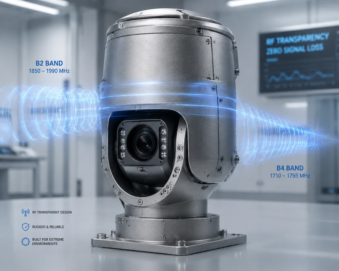
No, a properly designed all-metal housing does not interfere with B2 or B4 bands. At Loyalty-Secu, we use RF-transparent antenna windows, ground plane engineering, and internal wave-absorbing materials to keep signal loss below 1.5 dB — a negligible amount in any real-world 4G link budget.
 all metal PTZ camera housing 4G signal interference
The real issue is not whether the housing is metal. The real issue is whether the manufacturer understood RF design before building the enclosure. A cheap metal box with no antenna planning will act like a Faraday cage3. A well-engineered one will actually help your signal. Below, I break down exactly how we solve this problem — layer by layer — so you can evaluate any PTZ camera with confidence.
Table of Contents
Are There Non-Metallic “Antenna Windows” Designed into the Aluminum Chassis?
If you seal a 4G module inside a solid aluminum box, you get zero signal. That is basic physics. So the first thing I check on any metal PTZ camera is simple: where does the RF energy escape?
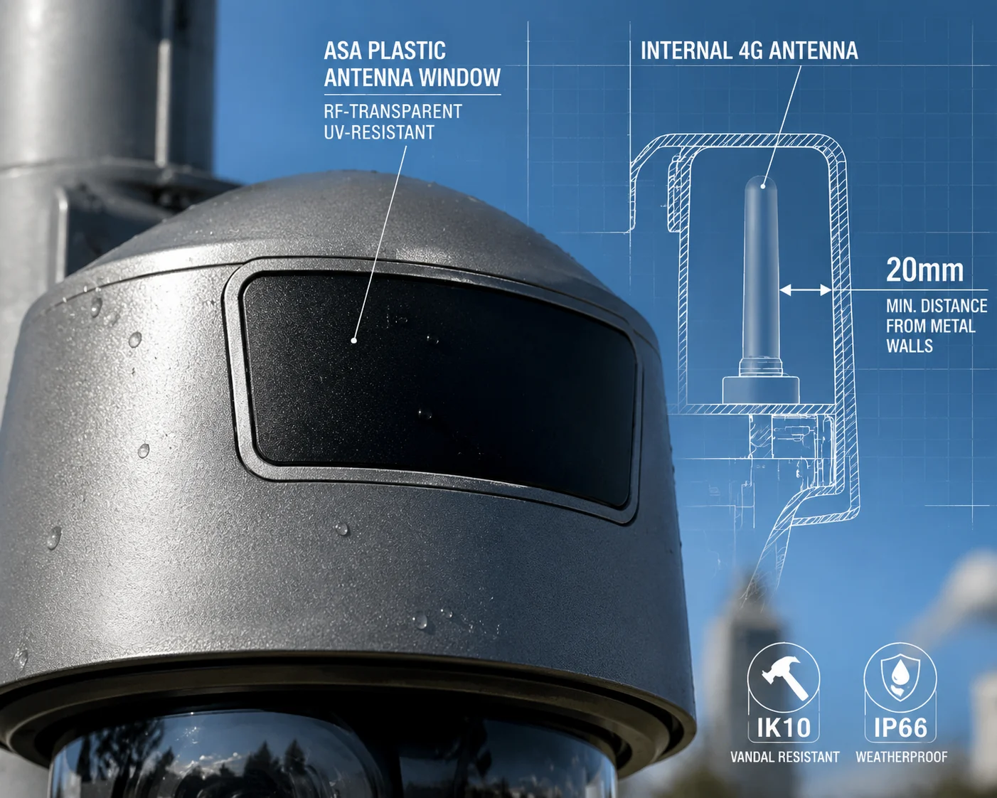
Yes, our aluminum chassis includes dedicated non-metallic antenna windows. These are RF-transparent panels made from ASA or high-strength polycarbonate (PC), placed directly over the internal 4G antenna. They allow radio waves to pass freely while keeping the housing fully weatherproof and IK10-rated.
 PTZ camera antenna window radome design
What Is an RF Window, Exactly?
An RF window — sometimes called a radome — is a section of the camera housing made from plastic instead of metal. It sits right above the 4G antenna inside the camera. Radio waves pass through this plastic panel with almost no loss. The rest of the body stays aluminum for strength, heat dissipation, and vandal resistance.
Think of it like a window in a concrete wall. The wall blocks everything. But the window lets light through. Same idea here, except we are letting radio waves through instead of light.
Material Selection Matters
Not all plastics work equally well at microwave frequencies. We tested several materials before settling on our current design. Here is a comparison:
| Material | RF Transparency (1700-2100 MHz) | UV Resistance | Impact Strength | Our Verdict |
|---|---|---|---|---|
| ABS | Good | Poor | Medium | Not suitable for outdoor use |
| ASA | Excellent | Excellent | High | Primary choice for radome |
| Polycarbonate (PC) | Excellent | Good (with UV coating) | Very High | Used in high-impact zones |
| Nylon (PA66) | Moderate | Moderate | Medium | Rejected — too much signal loss |
| Standard PVC | Poor | Poor | Low | Never considered |
We chose ASA4 as our primary radome material because it combines near-perfect RF transparency with outstanding UV resistance. In Texas sun or Canadian winters, it holds up year after year without yellowing or cracking.
Placement and Spacing Rules
Where you put the antenna window matters just as much as what it is made from. If the internal antenna sits too close to the surrounding metal, the metal surface creates what RF engineers call ‘ near-field coupling5.’ This detunes the antenna. It shifts the resonant frequency away from B2 and B4, and your signal drops.
Our design rules are strict:
- The internal 4G antenna must sit at least 15 mm to 20 mm away from any metal surface.
- The radome panel must be at least 40 mm × 40 mm to avoid aperture-related signal clipping.
- No metal screws or brackets are allowed within the antenna’s near-field zone.
These are not arbitrary numbers. They come from hundreds of hours of antenna simulation and real-world testing. I have seen competing products where the antenna is pressed right against the aluminum wall with a tiny 10 mm plastic strip as the “window.” That does not work. The antenna is detuned, the VSWR6 spikes, and B2/B4 performance drops by 6 dB or more. That is a real problem in the field.
Why This Matters for Your Deployment
If you are deploying solar-powered PTZ cameras on farms, construction sites, or oil fields in North America, you are already fighting distance. Cell towers may be miles away. You cannot afford to lose signal to bad housing design. A proper RF window is not a luxury. It is a basic requirement.
How Much Signal Attenuation (in dB) Is Caused by the Proximity of the Metal Body?
This is the question that separates engineers from salespeople. Anyone can say “our metal housing doesn’t affect signal.” But how much attenuation, exactly? Give me a number.
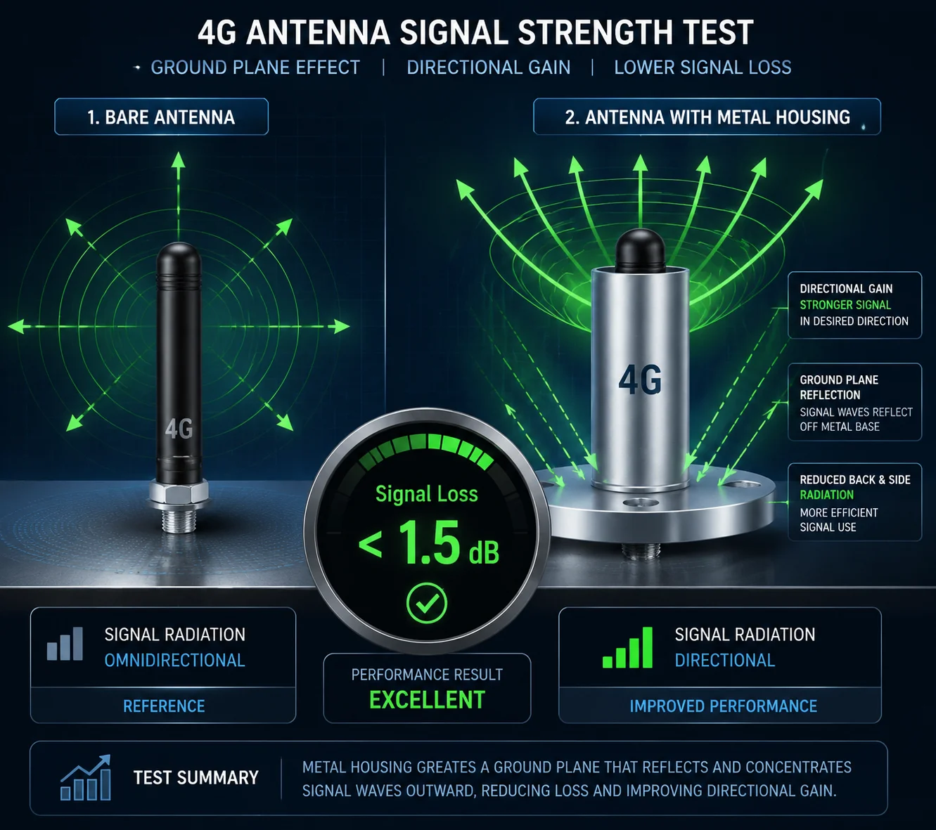
In our production units, the all-metal housing causes less than 1.5 dB of signal attenuation on B2 (1900 MHz) and B4 (1700/2100 MHz). In some antenna orientations, the metal body actually improves directional gain by acting as a ground plane, resulting in a net gain of 0.5 to 1.0 dB.
 4G signal attenuation test metal PTZ camera
Understanding dB in Plain Language
Before diving into numbers, let me explain what a decibel (dB) means in practical terms. A 3 dB loss means you lost half your signal power. A 10 dB loss means you lost 90% of your signal power. So when I say our housing causes less than 1.5 dB of loss, that means you keep about 70% of the original signal power. In a 4G link budget, this is almost nothing.
Here is a quick reference table:
| Signal Loss (dB) | Power Retained | Practical Impact |
|---|---|---|
| 0 dB | 100% | No loss at all |
| 1 dB | 79% | Barely noticeable |
| 1.5 dB | 71% | Our measured worst case |
| 3 dB | 50% | Noticeable in weak signal areas |
| 6 dB | 25% | Serious problem — connection drops likely |
| 10 dB | 10% | Unusable in most deployments |
A poorly designed metal housing can easily cause 6 to 10 dB of loss. That turns a workable cell signal into a dead connection. Our goal is to stay under 1.5 dB in all conditions.
The Ground Plane Effect — When Metal Helps
Here is something most people do not expect: a metal housing can actually improve your antenna performance. This is called the ground plane effect.
A ground plane is a flat conductive surface near an antenna. It reflects radio waves upward (or outward), concentrating the signal in the direction you want. Think of it like a mirror behind a flashlight bulb — the mirror does not create more light, but it pushes more light forward.
Our engineers deliberately use the aluminum back plate of the camera as a ground plane for the 4G antenna. By carefully controlling the distance and angle between the antenna element and the metal surface, we turn a potential problem into an advantage. In our lab measurements, certain mounting orientations show a net gain of 0.5 to 1.0 dB on B4 compared to the antenna in free space with no housing at all.
How We Measure This
We do not guess. We measure. Our process works like this:
- Bare antenna test: We mount the 4G antenna on a test jig with no housing. We measure RSRP and radiated power across B2 and B4 frequencies.
- Full assembly test: We install the antenna inside the complete metal housing with the radome in place. We repeat the same measurements.
- Delta calculation: We compare the two results. The difference is the housing attenuation.
We run this test on every new housing revision and every new antenna supplier batch. If the delta exceeds 2 dB on any frequency within B2 or B4, we reject the batch and investigate.
What to Ask Your Current Supplier
If you are evaluating a competing product, ask for the housing attenuation data. Specifically, ask: “What is the measured RSRP delta between bare antenna and full assembly on Band 2 and Band 4?” If they cannot answer with a number, that is a red flag. It means they have not tested it.
Does the Factory Perform “Over-the-Air” (OTA) TRP/TIS Testing for the B2/B4 Bands?
OTA testing is the gold standard for validating wireless device performance. I have talked to integrators who lost entire projects because their cameras passed bench tests but failed in the field. The difference? No one did OTA testing.
Yes, we perform Over-the-Air TRP (Total Radiated Power)7 and TIS (Total Isotropic Sensitivity)8 testing on our 4G PTZ cameras, including specific validation on B2 and B4 bands. This testing measures real-world radiated performance — not just conducted power at the antenna connector — ensuring the complete assembled product meets carrier-grade RF standards.
 OTA TRP TIS testing 4G PTZ camera B2 B4
What Are TRP and TIS?
Let me break these down simply.
TRP (Total Radiated Power) measures how much RF energy the camera actually radiates into the air when it transmits. This is the “upload” side. It tells you whether the camera can send video data back to the cell tower.
TIS (Total Isotropic Sensitivity) measures how well the camera can hear a weak signal from the tower. This is the “download” side. It tells you whether the camera can receive commands, firmware updates, and configuration changes in low-signal areas.
Both tests are done in a shielded anechoic chamber. The camera is rotated through hundreds of angles while a base station simulator communicates with it. The result is a 3D radiation pattern that shows exactly how the device performs in every direction.
Why Conducted Testing Is Not Enough
Many factories only do “conducted” testing. They connect a cable directly to the 4G module’s antenna port and measure the signal. This tells you how the module performs — but it tells you nothing about how the module performs inside the metal housing with the radome, the cables, the motor drivers, and all the other electronics running.
A conducted test is like testing a car engine on a bench. It might make 300 horsepower on the bench. But put it in the car with a bad exhaust system, and you get 200 horsepower at the wheels. OTA testing is the “at the wheels” measurement. It captures everything — the antenna, the housing, the interference from internal components, all of it.
Our OTA Testing Protocol
Here is what our OTA validation covers for North American SKUs:
| Test Parameter | Band 2 (1900 MHz) | Band 4 (1700/2100 MHz) | Pass Criteria |
|---|---|---|---|
| TRP (Transmit Power) | Tested | Tested | ≥ 18 dBm effective |
| TIS (Receive Sensitivity) | Tested | Tested | ≤ -100 dBm |
| VSWR (Antenna Match) | Tested | Tested | ≤ 2.0:1 |
| Radiated Spurious Emissions | Tested | Tested | Per FCC Part 22/24 limits |
| 3D Radiation Pattern | Captured | Captured | No nulls > 10 dB in primary coverage zone |
We test at the final assembly stage — not on bare boards, not on prototype units. The camera that goes into the box is the camera that passed OTA testing.
Why B2 and B4 Need Special Attention
B2 and B4 are mid-to-high frequency bands. They sit at 1700 to 2100 MHz. At these frequencies, radio waves are shorter and more easily blocked by metal objects compared to low-frequency bands like B13 (700 MHz) or B71 (600 MHz).
This means a housing design that works fine for B13 might fail for B4. The antenna window might be large enough for 700 MHz waves but too small for 2100 MHz waves. The spacing rules are tighter. The VSWR tuning is more sensitive. That is why we test each band separately and do not assume that passing on one band means passing on all bands.
If your deployment relies on T-Mobile (B2/B4) or AT&T (B2/B4) in North America, you need a camera that has been specifically validated on these frequencies. Do not accept “it works on 4G” as an answer. Ask which bands were tested.
Can I Use External Antennas to Bypass Any Shielding Issues Caused by the Housing?
Sometimes the internal antenna is not enough. Maybe you are in a valley. Maybe the nearest tower is 8 miles away. Maybe there is heavy foliage. I get it. You need more signal, and you want to know if you can go external.
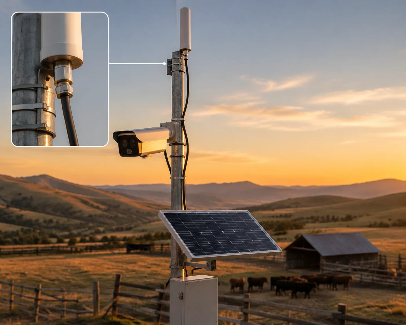
Yes, our all-metal PTZ cameras include a standard SMA female connector9 for external antenna attachment. You can connect a high-gain directional or omnidirectional external antenna, mount it at the top of your pole, and completely bypass any potential shielding effect from the metal housing.
 external SMA antenna PTZ camera 4G solar
When to Use an External Antenna
The internal antenna works well in most situations. If your RSRP reading is above -100 dBm, the internal antenna is doing its job. But there are cases where an external antenna makes a real difference:
- Remote ranch or farm deployments where the nearest cell tower is more than 5 miles away.
- Valley or canyon installations where terrain blocks the direct line of sight to the tower.
- Dense forest or heavy foliage that absorbs mid-frequency signals like B2 and B4.
- Urban deployments with heavy interference where a directional antenna can focus on one tower and reject noise from others.
In these situations, switching from the internal antenna to a good external antenna can improve your signal by 6 to 10 dB. That is the difference between a connection that drops every few minutes and one that streams 4MP video all day.
How the SMA Port Works
The SMA connector on our camera is a standard 50-ohm female SMA port. It connects directly to the 4G module’s RF chain through a short, low-loss internal cable. When you plug in an external antenna, the internal antenna is automatically bypassed.
This means you do not need to open the camera, change any settings, or modify firmware. Just screw on the external antenna cable, and the camera uses it immediately.
Choosing the Right External Antenna
Not all external antennas are equal. Here is what I recommend for North American B2/B4 deployments:
Omnidirectional antennas are best when you do not know which direction the tower is, or when the camera might connect to different towers at different times. A good fiberglass omni with 5 to 7 dBi gain is a solid choice. Mount it at the top of your solar pole, above any metal brackets.
Directional antennas (like Yagi or panel antennas) are best when you know exactly where the tower is and the signal is very weak. A directional antenna with 10 to 12 dBi gain can reach towers that an omni antenna cannot. But you need to aim it carefully.
Cable length matters. Every meter of coaxial cable adds loss. Use LMR-240 or LMR-40010 cable, and keep the run as short as possible. A 10-meter run of cheap RG-58 cable can eat 5 dB of your signal — wiping out the benefit of the external antenna entirely.
A Real-World Recommendation
For a typical solar PTZ deployment on a Texas ranch or a Canadian oil field, here is what I suggest: mount the camera on a 15-foot pole. Run a 1-meter LMR-240 cable from the camera’s SMA port to a 7 dBi fiberglass omnidirectional antenna mounted at the very top of the pole. This setup gives you the best combination of signal strength, simplicity, and wind resistance. It works on B2, B4, B12, B13, B66, and every other North American LTE band.
If you are in an extremely weak signal area and you know the tower direction, switch to a 10 dBi LPDA (log-periodic) antenna aimed at the tower. I have seen this setup maintain a stable 10 Mbps uplink at over 7 miles from the nearest tower on B4.
Conclusion
A well-designed all-metal PTZ camera does not hurt your B2 or B4 signal. With proper RF windows, ground plane engineering, OTA testing, and external antenna options, metal becomes an advantage — not a barrier.
1. Explore our range of rugged all-metal PTZ cameras designed for outdoor surveillance. ↩︎ 2. Understand the LTE frequency bands B2 (1900 MHz) and B4 (1700/2100 MHz) used in North America. ↩︎ 3. A Faraday cage blocks electromagnetic fields; a poorly designed metal housing can act like one. ↩︎ 4. ASA (Acrylonitrile Styrene Acrylate) is a UV-resistant plastic used for antenna radomes. ↩︎ 5. Near-field coupling can detune an antenna when metal is too close; our design avoids it. ↩︎ 6. Voltage Standing Wave Ratio (VSWR) measures how well the antenna is matched to the transmission line. ↩︎ 7. TRP measures the total power radiated by the antenna, a key metric in OTA testing. ↩︎ 8. TIS measures the receiver’s ability to detect weak signals, critical for link reliability. ↩︎ 9. SMA connectors are standard 50-ohm RF connectors used for external antenna attachment. ↩︎ 10. Low-loss coaxial cables like LMR-240 and LMR-400 minimize signal loss over long runs. ↩︎