
I get this question a lot from system integrators who need live coordinate data on their video feeds. It matters because a wrong setup can ruin your evidence or break your workflow.
Yes, real-time XY tracking coordinates can be overlaid directly onto the RTSP stream. There are two main methods: hardware-level OSD burn-in, which permanently stamps coordinates into every video frame, and dynamic metadata overlay, which sends coordinate data as a separate track alongside the video. Each method fits different project needs.
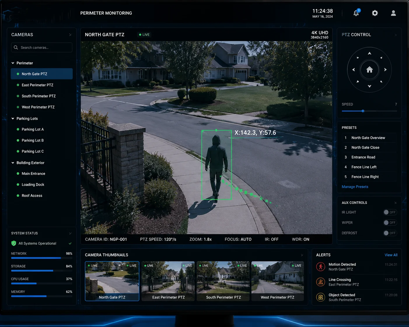 real-time XY tracking coordinates overlay on RTSP stream PTZ camera
The right choice depends on your end goal. If you need tamper-proof evidence, you burn it in. If you need flexible, interactive data for your VMS or custom software, you use metadata. Below, I break down the most common questions my clients ask about this topic. I also share the real-world challenges we solve in our 4G solar PTZ deployments.
Table of Contents
Will the AI Bounding Boxes Be Permanently Burned into the Recorded 4K Video Evidence?
This is a concern I hear from almost every project manager. Nobody wants to discover after a six-month deployment that their evidence footage is either missing critical data or cluttered with boxes they cannot remove.
If you enable the “Burn-in Smart Event Info” option in the camera firmware, yes, the AI bounding boxes and XY coordinates will be permanently embedded into every recorded frame. This means the data becomes part of the pixel content. No one can remove or alter it after recording. This is ideal for forensic evidence but irreversible.
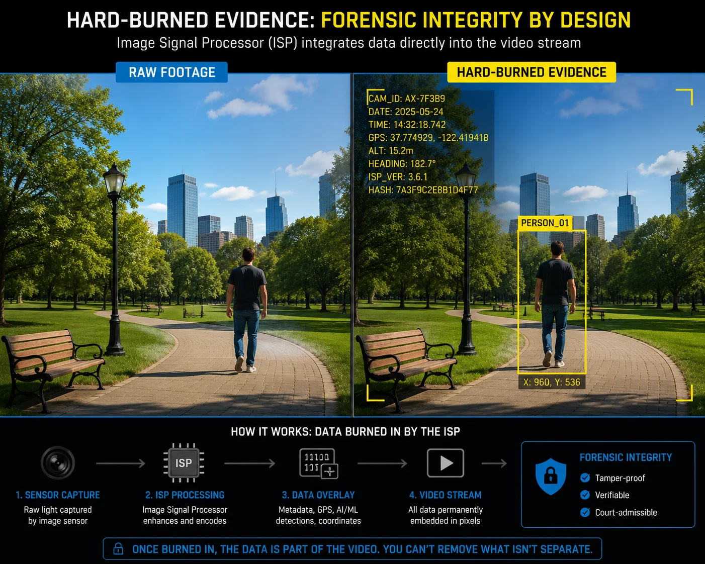 AI bounding boxes burned into 4K video evidence PTZ camera
How Hard-Burned OSD Actually Works
Let me explain what happens inside the camera when you turn on this feature. The camera’s ISP (Image Signal Processor)8 is the chip that processes the raw image from the sensor. Before the ISP hands the image to the H.265 encoder, it draws the bounding box and coordinate text directly onto the image pixels. By the time the encoder compresses the frame, those boxes are just part of the picture. They are no different from the timestamp in the corner.
This means every device that plays the video will see the boxes. It does not matter if you use VLC5, a cheap DVR, or a high-end VMS like Milestone4. The data is always visible.
When to Use Burn-In and When to Avoid It
Here is the key question: Who is your end user?
If your client is a law enforcement agency, a border patrol unit, or a critical infrastructure operator, they often require that detection events be visually documented in the footage itself. In court, a lawyer can point to the screen and say, “The system detected an intruder at pixel coordinates (1423, 876) at 02:14:07 AM.” That is powerful evidence.
But if your client is a smart city operator who feeds video into a centralized AI platform for secondary analysis, burned-in boxes become noise. The secondary AI system might try to detect the bounding box itself as an object. I have seen this happen. It creates false positives.
Evidence Integrity vs. Analytical Flexibility
| Factor | Hard-Burned OSD | Clean Video (No Burn-In) |
|---|---|---|
| Court admissibility | High — data is tamper-proof | Requires separate metadata log as proof |
| Secondary AI analysis | Poor — boxes interfere with detection | Excellent — clean frames for reprocessing |
| Storage impact | Minimal increase (~1-2%) | No impact |
| User control | None after recording | Full control via VMS |
| Playback compatibility | Universal | Depends on VMS metadata support |
My recommendation: if your project serves dual purposes (evidence + analytics), record two streams. Use the main stream with burn-in for evidence storage. Use the sub-stream clean for your AI backend. Our firmware supports this dual-stream configuration out of the box.
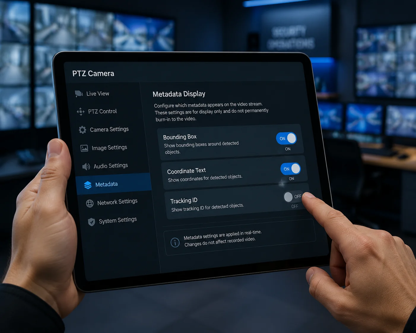
Can I Toggle the XY Coordinate Overlay On/Off Through the Camera’s OSD Settings?
I had a client in Texas last year who wanted coordinates visible during live monitoring but completely hidden during playback for his customer’s privacy review. He assumed a simple toggle would handle it. The reality is more nuanced.
Yes, you can toggle the XY coordinate overlay on or off through the camera’s OSD menu, but only if you are using the metadata overlay method. If you chose the hard burn-in method, the toggle only affects future frames. It cannot remove coordinates from frames already recorded. For full on/off flexibility, the metadata approach is the correct choice.
 toggle XY coordinate overlay OSD settings PTZ camera
Understanding the Two Toggle Behaviors
When you go into the camera’s OSD settings and find the “Smart Overlay” or “AI Display” option, what happens when you flip it depends entirely on which overlay method your firmware is using.
Scenario A — Hard Burn-In Mode: You turn off the toggle. The camera stops drawing boxes on new frames. But every frame recorded before that moment still has the boxes baked in. There is no undo. Think of it like writing with a permanent marker on a photograph. You can stop writing, but you cannot erase what is already there.
Scenario B — Metadata Mode: You turn off the toggle. The camera still sends the metadata stream (the XY coordinates in XML or JSON format). But the camera’s own preview stops rendering the overlay. Your VMS can independently decide whether to display the coordinates. This gives you layer-by-layer control.
OSD Menu Options in Our Firmware
Our PTZ cameras7 provide granular control over what gets displayed. Here is what you can configure:
- Bounding Box Display: On / Off
- Coordinate Text (X, Y): On / Off
- Object Classification Label (Person, Vehicle, etc.): On / Off
- Confidence Score: On / Off
- Tracking ID Number: On / Off
Each of these can be toggled independently. So if your client only wants to see the tracking ID and the bounding box but not the raw coordinates, that is a simple firmware setting.
A Common Mistake I See in the Field
Many integrators configure the OSD overlay during bench testing and forget to adjust it before deployment. Then the end user complains: “Why do I see numbers all over my screen?” Or worse, they turn everything off during setup and then six months later ask, “Where is my coordinate data?”
My advice: create a configuration checklist for each project. Document exactly which overlays are on, which are off, and whether you are using burn-in or metadata mode. Save the config file. Our cameras support config export and import, so you can clone settings across hundreds of units.
Toggle Behavior Summary
| Action | Hard Burn-In Mode | Metadata Overlay Mode |
|---|---|---|
| Toggle OFF in OSD | Stops burning on new frames only | Stops rendering on camera preview; metadata still transmits |
| Toggle ON in OSD | Resumes burning on new frames | Resumes rendering on camera preview |
| Effect on past recordings | No change — boxes are permanent | No change — metadata is always stored separately |
| VMS independent control | Not possible | Fully possible |
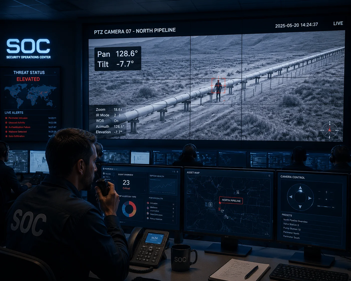
How Does the Coordinate Overlay Assist My Team in Coordinating Manual PTZ Responses?
In large perimeter security projects, I often see a disconnect between the operator who spots the threat and the field team that responds. The operator says, “It is on the left side of the screen.” That is useless when the camera covers a 2-kilometer fence line.
The XY coordinate overlay gives your operators a precise, numerical language to communicate target positions. Instead of vague descriptions, your control room can radio the field team with exact pan and tilt angles derived from the XY data. This cuts response coordination time significantly and eliminates guesswork in manual PTZ control.
 XY coordinate overlay PTZ manual response coordination
From Pixel Coordinates to Real-World Positions
Here is how the workflow actually functions in a well-configured system. The camera’s AI detects a person at pixel coordinates $(1423, 576)$ on a $1920 \times 1080$ frame. The firmware knows the current pan angle is 127.4° and the tilt angle is -8.2°. It also knows the field of view at the current zoom level is 6.3° horizontal.
Using simple math, the firmware calculates that the target is approximately 1.2° to the right of the frame center and 0.5° above the center. It then outputs the absolute bearing: Pan 128.6°, Tilt -7.7°. This is what gets displayed on the overlay or sent via metadata.
Why This Matters for Manual Override
In many of our 4G solar PTZ deployments1, the camera runs in auto-tracking mode most of the time. But there are moments when the operator needs to take manual control. Maybe the AI lost the target behind a tree. Maybe there are two targets and the operator wants to focus on the second one.
Without coordinate data, the operator has to visually scan the scene, guess where the target went, and manually jog the PTZ. With coordinate data, the operator sees the last known position — say, Pan 214.3°, Tilt -3.1° — and can punch those numbers directly into the PTZ controller. Some VMS platforms even support “click to go to coordinate,” which makes this instant.
Coordinating Between Multiple Cameras
This gets even more powerful when you have multiple PTZ cameras covering the same area from different angles. If Camera A reports a target at geographic bearing 214°, Camera B can automatically slew to the same bearing. Or the operator can manually command Camera B to look at 214°. The coordinate overlay makes this cross-camera handoff possible without the operator needing to memorize which camera covers which zone.
Real-World Scenario: Pipeline Monitoring in West Texas
One of our clients monitors a 15-mile pipeline corridor with six solar PTZ units. Each camera covers roughly 2.5 miles. When Camera 3 detects a vehicle near the pipeline at a specific coordinate, the operator sees the pan/tilt values on screen. He radios the patrol truck: “Target at Camera 3, bearing 187 degrees, approximately 800 meters from the access road junction.” The patrol team knows exactly where to go. Before they had coordinate overlays, the radio call was: “Camera 3 sees something on the right side.” The patrol team would drive around for 20 minutes trying to find it.
That is the difference coordinate data makes. It turns vague alerts into actionable intelligence.
Does the Overlay Affect the H.265 Compression Efficiency of the Live Video Stream?
This is the question that separates casual buyers from serious engineers. Every system integrator I work with who manages bandwidth-constrained 4G deployments asks this. And they should. Because in a solar-powered site with a 4G SIM card, every kilobit matters.
The impact depends on which overlay method you use. Hard-burned OSD adds high-contrast text and boxes to the image, which slightly reduces H.265 compression efficiency because the encoder must preserve those sharp edges. The increase is typically 3-8% in bitrate. Metadata overlay has zero impact on video compression because the coordinate data travels in a separate, lightweight channel.
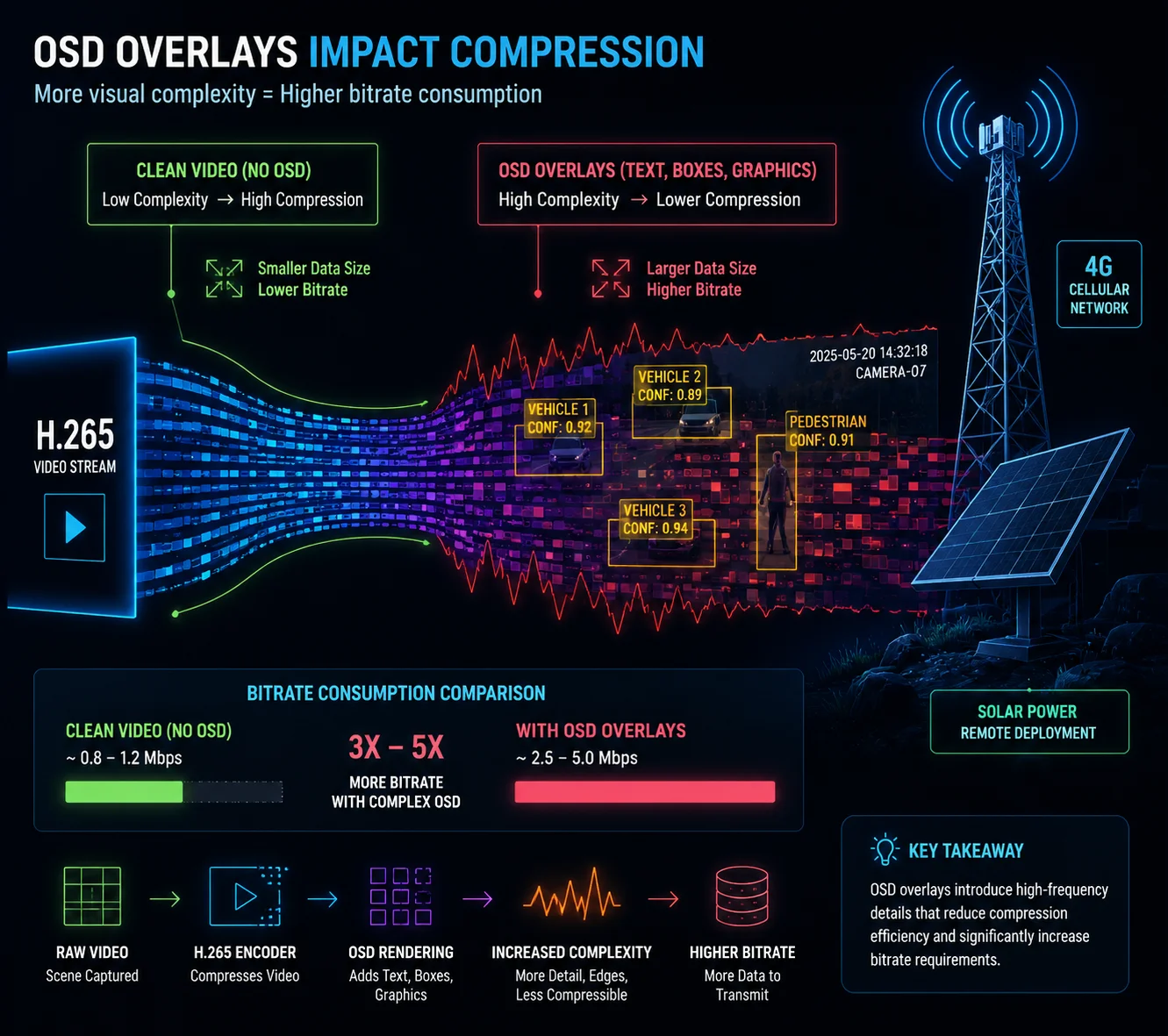 H.265 compression efficiency coordinate overlay impact
Why Burn-In Hurts Compression (A Little)
H.265 (HEVC) is very good at compressing natural scenes. Grass, sky, trees, roads — these have smooth gradients and predictable motion. The encoder exploits this predictability to achieve high compression ratios.
But when you burn sharp, high-contrast text and geometric shapes (like bounding boxes) into the image, you introduce elements that the encoder cannot predict well. A white “X:1423 Y:576” label on a dark background creates hard edges that require more bits to encode accurately. The encoder has to spend extra bits to keep those characters readable.
How Much Extra Bandwidth Are We Talking About?
In our lab tests, here is what we measured on a typical outdoor scene at 1080p, 25fps, H.265 Main Profile6:
| Overlay Configuration | Average Bitrate | Increase vs. Clean |
|---|---|---|
| No overlay (clean video) | 2.8 Mbps | Baseline |
| Timestamp only | 2.85 Mbps | +1.8% |
| Timestamp + 1 bounding box + XY text | 2.92 Mbps | +4.3% |
| Timestamp + 5 bounding boxes + XY text | 3.03 Mbps | +8.2% |
| Metadata overlay (no burn-in) | 2.8 Mbps + 3 kbps metadata | ~0% on video stream |
As you can see, one or two bounding boxes barely matter. But if you are monitoring a busy intersection with 10+ simultaneous detections, the bitrate creep adds up. On a 4G connection with a monthly data cap, that 8% increase over 30 days could cost your client real money.
The 4G Bandwidth Budget Problem
Let me put this in perspective. A typical 4G SIM plan for an industrial IoT device in the US gives you 50-100 GB per month. At 2.8 Mbps continuous streaming, you burn through about 900 GB per month. Obviously, nobody streams 24/7 at full bitrate on 4G. You use motion-triggered recording, adaptive bitrate, and scheduled streaming windows.
But even with those optimizations, an 8% bitrate increase means 8% more data consumption. Over a 100-camera deployment, that is significant.
Our Approach: Smart Overlay Scheduling
This is why we built a feature called ‘Smart Overlay Scheduling’2 into our firmware. It works like this:
- During alarm events, the camera automatically enables the coordinate burn-in so the evidence clip has full visual data.
- During normal surveillance (no alarm), the camera disables the burn-in and sends coordinates only via the metadata channel.
- The transition happens within one GOP (Group of Pictures)9, which is typically 2 seconds.
This gives you the best of both worlds. Your evidence clips have burned-in coordinates for court. Your routine surveillance footage stays clean and bandwidth-efficient. And your 4G data bill stays under control.
PTS Synchronization Over 4G Networks
There is one more technical detail that matters for 4G deployments. When the camera sends the video stream and the metadata stream over a 4G connection, network jitter can cause them to arrive at the VMS at different times. The video frame might arrive 500ms late, but the tiny metadata packet arrives on time.
If your VMS naively overlays the metadata as it arrives, the bounding box will appear to “lead” the target. The box moves before the person does. This looks broken.
Our firmware solves this with PTS (Presentation Time Stamp) synchronization3. Every metadata packet carries the exact same timestamp as the video frame it belongs to. The VMS buffers both streams and aligns them by timestamp before rendering. The result: the bounding box stays locked to the target, even on a choppy 4G connection in a remote Texas oil field.
Conclusion
XY coordinate overlay on RTSP streams is fully achievable. Choose hard burn-in for tamper-proof evidence. Choose metadata overlay for flexibility and bandwidth savings. Match the method to your project’s real needs.
1. Solar-powered PTZ cameras using 4G cellular networks for remote surveillance. ↩︎ 2. Firmware feature that enables burn-in only during alarms to save bandwidth. ↩︎ 3. Timestamp used to synchronize video and metadata streams to maintain alignment. ↩︎ 4. Popular video management software platform that supports metadata overlay. ↩︎ 5. Open-source media player that can display video streams with overlays. ↩︎ 6. Video compression standard also known as HEVC, used for efficient video streaming. ↩︎ 7. Camera capable of panning, tilting, and zooming, commonly used in surveillance. ↩︎ 8. Chip that processes raw image data before encoding, where burn-in occurs. ↩︎ 9. Sequence of frames in compressed video used for encoding efficiency. ↩︎